1
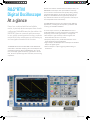
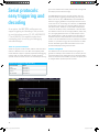
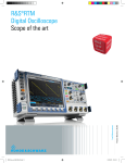
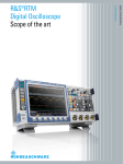
RTM_bro_en_3606-8066-12.indd 1 Product Brochure | 01.04 Test & Measurement R&S®RTM Digital Oscilloscope Scope of the art 05.09.2013 12:54:14 R&S®RTM Digital Oscilloscope At a glance Ease of use, combined with fast and reliable results, is precisely what users expect from a bench oscilloscope. Rohde & Schwarz has the solution: the R&S®RTM. Users can now work with two screens in one, quickly access important functions, evaluate results while other oscilloscopes are still booting up and see signals otherwise lost in the noise. The R&S®RTM models with 350 MHz or 500 MHz bandwidth offer a maximum sampling rate of 5 Gsample/s and a maximum memory depth of 20 Msample. As a result, they can display signals accurately, right down to the details, as well as provide high time resolution, even for long sequences. Besides the common measurement and analysis tools, the R&S®RTM oscilloscopes have special features that help users to achieve the desired results quickly during debugging and signal analysis. At the push of a button, for example, the QuickMeas function graphically displays the key measurement values for the signal that is currently active and updates them continuously. The R&S®RTM oscilloscopes are ideal for many different applications, including the development, production and servicing of embedded hardware. As a true scope of the art, the R&S®RTM meets the increased demands on bench oscilloscopes, providing time, frequency, protocol and logic analysis in a single box: ❙❙ Time analysis: high sensitivity to detect signals that would otherwise be lost in the noise ❙❙ Frequency analysis: fast, reliable fault detection in the signal spectrum with integrated FFT ❙❙ Logic analysis: 20 Msample with 5 Gsample/s for detailed analysis of digital signals ❙❙ Protocol analysis: simple triggering and decoding of serial buses 2 RTM_bro_en_3606-8066-12.indd 2 05.09.2013 12:54:18 R&S®RTM Digital Oscilloscope Benefits and key features Signal analysis: quick results ❙❙ Signal details at the push of a button: QuickMeas ❙❙ Measurement results in detail: powerful cursor functions ❙❙ Focus on details: zoom and markers ❙❙ Fast time to results: switch on, measure and done ▷▷ page 4 Debugging: everything at a glance ❙❙ Settings in only seconds: mask test ❙❙ Integrated: FFT analysis ❙❙ To the point: comprehensive triggering capabilities ▷▷ page 6 Usability: smart concepts ❙❙ Easy orientation: color-coded controls ❙❙ Fast access: flat menus ❙❙ Fault-tolerant: undo/redo function ❙❙ See more: high-resolution XGA display ❙❙ Two displays instead of one: VirtualScreen ❙❙ Remote control, data exchange: diverse interfaces ❙❙ Multilingual: choice of nine languages ▷▷ page 8 Accuracy: our strength ❙❙ 1 mV/div: full measurement bandwidth ❙❙ Frontends: low noise and low crosstalk ❙❙ Deep memory: acquire long sequences ▷▷ page 10 Logic analysis: more details ❙❙ Precision measurement: up to 5 Gsample/s sampling rate ❙❙ Deep memory: acquire long sequences ❙❙ Better overview: VirtualScreen ❙❙ Everything at a glance: activity display ▷▷ page 11 Serial protocols: easy triggering and decoding ▷▷ page 12 For every application: probes and accessories ▷▷ page 13 Universal: Numerous functions for many applications ❙❙ Electronics development ❙❙ Production ❙❙ Education ❙❙ Service ▷▷ page 16 Models Base unit Bandwidth Channels R&S®RTM2032 350 MHz 2 R&S®RTM2034 350 MHz 4 R&S®RTM2052 500 MHz 2 R&S®RTM2054 500 MHz 4 RTM_bro_en_3606-8066-12.indd 3 Safe investment: flexible and extensible ▷▷ page 17 Rohde & Schwarz R&S®RTM Digital Oscilloscope 3 05.09.2013 12:54:19 Signal analysis: quick results Frequently, measurement signals need to be analyzed in detail, and their properties (e.g. frequency or rise and fall times) have to be determined. The R&S®RTM oscilloscopes offer powerful tools that facilitate signal analysis and deliver precise results. QuickMeas: key results at the push of a button Measurement value Display Vp+ Positive peak voltage Vp– Negative peak voltage tr Rise time tf Fall time Mean Mean voltage Vpp Peak-to-peak voltage RMS RMS value T Time f Frequency Signal details at the push of a button: QuickMeas The QuickMeas function offered by the R&S®RTM oscilloscopes is unique. At the push of a button, it displays the key measurement values (see table) for a currently active signal using auxiliary lines and markers, and results are updated continuously. In addition to the QuickMeas results, the oscilloscopes also provide the customary automatic measurement functions such as measurement of peak-to-peak voltage or signal frequency. The results are presented in tabular form, with statistical evaluation if desired. Measurement results in detail: powerful cursor functions Cursor-based measurements are normally limited to horizontal or vertical cursors. The R&S®RTM oscilloscopes are different: Their cursor menu offers additional functions, familiar from the automatic measurements. For example, this includes measurement of the mean voltage or RMS value, as well as a pulse counter. The advantage is that users can limit measurements to a specific section of the signal. Graphical display directly on the waveform Tabular display on the bottom right of the screen QuickMeas: automatic measurement and graphical display at the push of a button. 4 RTM_bro_en_3606-8066-12.indd 4 05.09.2013 12:54:19 Three cursors are used for measuring ratios. The RatioX measurement, for example, determines the duty cycle of a pulsed signal conveniently and in a single step. Another useful cursor function is “Set to Wave”. At the push of a button, this function automatically assigns the cursors to the corresponding signals, eliminating the need to select and position the cursors. Fast time to results: switch on, measure and done Optimized for fast signal analysis, the R&S®RTM oscilloscope starts up within only a few seconds. The most important measurement results for an active signal can be obtained at the push of a button (QuickMeas function), enabling fast signal characterization. The R&S®RTM is already analyzing signals while other oscilloscopes are still booting up. Focus on details: zoom and markers The R&S®RTM oscilloscopes' sampling rate of up to 5 Gsample/s enables them to achieve a high time resolution. The memory depth of up to 20 Msample makes it possible to acquire long signal sequences, e.g. 4 ms at a sampling rate of 5 Gsample/s. Using the zoom function, the signal can be expanded up to 200 000:1 in order to investigate details. Navigating in the zoom window to a specific point on the waveform using the position knob is usually very tedious. The R&S®RTM oscilloscopes are different: They offer eight user-definable event markers that can be used to highlight any events in the signal. Users can then conveniently jump between the markers using the Next and Prev buttons. Special cursor measurement: determination of the duty cycle of a pulsed signal. Rohde & Schwarz R&S®RTM Digital Oscilloscope 5 RTM_bro_en_3606-8066-12.indd 5 05.09.2013 12:54:19 Debugging: everything at a glance Discovering signal faults can be very timeconsuming, but the R&S®RTM oscilloscopes simplify the search process. The mask test finds rare signal faults while the FFT provides a look at the spectrum of a signal. Settings in only seconds: mask test Mask tests quickly reveal whether a specific signal lies within defined tolerance limits and use statistical pass/fail evaluation to assess the quality and stability of a device under test. Signal anomalies and expected results are easy to identify by stopping the measurement if the mask is violated. The mask test function is a standard feature in the R&S®RTM oscilloscopes. It is easy to operate and can be flexibly configured. A new mask can be created from a reference signal with just a few keystrokes. Existing masks can be loaded from the internal memory or from a USB flash drive. Any violation of an active mask can result in the automatic stopping of acquisition or the output of an acoustic signal. A mask test delivers the following results: total number of acquired waveforms, overall duration of test and number of successful and faulty sweeps. The mask tests can be remotely controlled, which is good for quality tests in automated production applications. Mask test: mask definition from a reference signal. 6 RTM_bro_en_3606-8066-12.indd 6 05.09.2013 12:54:19 Integrated: FFT analysis To the point: comprehensive triggering capabilities The FFT function has a dedicated button and enables users to detect and analyze faults within a signal's spectrum. With the FFT activated, the R&S®RTM oscilloscopes simultaneously provide a spectral display of the signal and a small time domain window for checking the sampling interval. The Autoset button is extremely convenient: The instrument automatically selects the amplitude and frequency scaling that optimally matches the measured signal. Without valid triggering, it is impossible to obtain a stable signal display on the screen or fast isolation of signal events of interest. The R&S®RTM oscilloscopes offer many trigger capabilities such as a pulse width or runt trigger. Complex trigger conditions as well as logical combinations of individual signals can also be implemented for digital channels. Dedicated keys on the front panel allow fast switching between the Auto and Normal trigger as well as selection of the trigger edge and source. The Trigger-Level rotary knob offers additional operating convenience: A single press sets the trigger level to 50 % of the signal amplitude. FFT analysis: fast identification of harmonics in the output voltage of a DC/DC converter. RTM_bro_en_3606-8066-12.indd 7 Rohde & Schwarz R&S®RTM Digital Oscilloscope 7 05.09.2013 12:54:20 Usability: smart concepts The R&S®RTM oscilloscopes are easy and intuitive to use. They make user wishes come true: Just unpack the instrument, switch it on and start measuring. Easy orientation: color-coded controls The controls for vertical settings and the trigger are colorcoded. Multicolor LEDs around the rotary knobs visualize the channel that is currently in focus. This color coding corresponds to the signal display on the screen, and this clarity allows smooth work, even during complex tests and measurements. Fast access: flat menus The logically grouped menus with flat structures provide a fast overview of the instrument settings. Dedicated keys are provided for the most frequently used functions. Numerous setups such as the logic trigger are supported by graphics. Controls on the R&S®RTM oscilloscopes Press to return to presettings Brilliant XGA color display Help: context-sensitive and always available VirtualScreen/ intensity Menus with flat structure Quickly ready for use thanks to fast booting 8 RTM_bro_en_3606-8066-12.indd 8 05.09.2013 12:54:22 Fault-tolerant: undo/redo function Remote control, data exchange: diverse interfaces Restoring previous settings is no problem with the undo/ redo function. Corrections are easy to make if the wrong key is pressed. The high-resolution 8.4" color XGA TFT display is one of the R&S®RTM oscilloscopes' highlights. This brilliant, sharp display clearly shows the measurement signals, right down to the smallest details. Three USB interfaces are available on the R&S®RTM oscilloscopes: two USB host ports – which can be used, for instance, to easily transfer screenshots or instrument settings to a USB flash drive – and one USB device port to remote control the oscilloscopes. The LAN interface for remote control or for accessing the instrument via a web browser comes as standard. A GPIB interface is available as an option. The DVI output controls a monitor or a data projector. Two displays instead of one: VirtualScreen Multilingual: choice of nine languages The large screen supports simultaneous display of analog and logic signals. The VirtualScreen of the R&S®RTM oscilloscopes can be expanded to 20 divisions for straightforward display of all signals. The visible section of the VirtualScreen is moved to the desired position using a rotary knob, facilitating detailed signal analysis without sacrificing the big picture. The R&S®RTM oscilloscopes are fluent in different languages. Users can choose from English, German, French, Spanish, Russian, simplified and traditional Chinese, Korean and Japanese. See more: high-resolution XGA display Extensive cursor-based measurement functions Key measurement results at the push of a button Fast access to logic and protocol analysis Fast access to important analysis functions via dedicated keys Undo/redo function to easily restore previous settings Easy search and navigation between signal events USB port for data exchange, documentation or firmware updates Color-coded controls visualize the channel in focus RTM_bro_en_3606-8066-12.indd 9 Rohde & Schwarz R&S®RTM Digital Oscilloscope 9 05.09.2013 12:54:24 Accuracy: our strength Frontends: low noise and low crosstalk The accuracy of a signal displayed on the screen heavily depends on the oscilloscope's inherent noise. For this reason, the R&S®RTM oscilloscopes have low-noise frontends and A/D converters. As a result, they are able to measure precisely, even at the smallest vertical resolutions. Rohde & Schwarz has many years of experience developing precision test and measurement equipment, which also benefits the R&S®RTM oscilloscopes. Tried and trusted Rohde & Schwarz quality is also available in bench oscilloscopes. This precision is retained even when additional channels are used. The R&S®RTM oscilloscopes have an excellent channel-to-channel isolation of > 50 dB up to 500 MHz, which ensures that the measurement signal from one channel has the lowest possible influence on signals from the other channels. Deep memory: acquire long sequences 1 mV/div: full measurement bandwidth With their input sensitivity of up to 1 mV/div, the R&S®RTM oscilloscopes offer high vertical resolution. Other oscilloscopes attain such high input sensitivity only by employing software-based zooming or by limiting the bandwidth. The R&S®RTM oscilloscopes, however, show a signal's real sampling points even at 1 mV/div, at full measurement bandwidth. This high measurement accuracy is particularly beneficial when measuring small signal amplitudes. The more details an oscilloscope can show, the higher the probability of detecting signal faults or important events. As a prerequisite, the oscilloscope must have a high time resolution, i.e. a high sampling rate. In addition, many applications require long acquisition cycles, for instance for analyzing transients or serial protocols. The R&S®RTM oscilloscopes boast impressive features. Compared to other oscilloscopes in this class, they offer a very high memory depth of 20 Msample with a time resolution of up to 200 ps (5 Gsample/s sampling rate). Acquisition cycle (as a function of sampling rate and memory depth) 10 ksample 1 Msample 10 Msample 20 Msample 5 Gsample/s 2 μs 200 μs 2000 μs 4000 μs 2.5 Gsample/s 4 μs 400 μs 4000 μs 8000 μs RMS: 82.46 µV Vpp: 560.00 µV Extremely low inherent noise, even for a vertical input sensitivity of 1 mV/div. 10 RTM_bro_en_3606-8066-12.indd 10 05.09.2013 12:54:24 Logic analysis: more details Fast and precise testing of embedded designs: 16 additional channels with the R&S®RTM-B1 logic analysis option. Precision measurement: up to 5 Gsample/s sampling rate The R&S®RTM oscilloscopes' sampling rate of up to 5 Gsample/s makes it possible to accurately measure the timing of logic signals. Since the signals can be precisely time-referenced to one another, timing and clock errors can be detected with greater ease, e.g. on serial or parallel bus signals. The R&S®RTM oscilloscopes use the high sampling rate over the entire acquisition time, ensuring high time resolution even for long acquisition cycles. Deep memory: acquire long signal sequences Logic signals are stored in the R&S®RTM with up to 20 Msample. This long acquisition cycle in combination with the high sampling rate makes it easy to detect timing errors even far from the trigger point, for instance. Better overview: VirtualScreen With comparable oscilloscopes in this class, the logic signal display is typically superimposed on the analog signal display. This makes viewing and analysis more difficult. The VirtualScreen of the R&S®RTM oscilloscopes uses a different approach: It doubles the usable screen area for clear display of the channels with no overlapping. Math, reference and logic signals can be displayed above or below the analog channels. Everything at a glance: activity display The R&S®RTM oscilloscopes' activity display provides a clear overview of the current status of all logic channels (high, low, toggle) regardless of the trigger settings. This allows the user to always see the status of all logic signals at a glance. Activity display: status information for the digital signals independent from acquisition and instrument settings. Rohde & Schwarz R&S®RTM Digital Oscilloscope 11 RTM_bro_en_3606-8066-12.indd 11 05.09.2013 12:54:25 Serial protocols: easy triggering and decoding As an option, the R&S®RTM oscilloscopes can support triggering and decoding of the protocols for serial interfaces such as I2C, SPI, UART/RS‑232, I2S and CAN/LIN. This capability makes them outstanding tools for verifying and debugging embedded designs. ger on the content of the serial protocol that is being used and display the decoded message. The R&S®RTM oscilloscopes provide versatile tools for protocol-specific triggering and decoding of serial interfaces such as I2C, SPI, UART/RS‑232, I2S and CAN/LIN. Extensive trigger capabilities help acquire relevant events. In the case of an I2C message, for instance, the R&S®RTM oscilloscopes can trigger on a specific address with specific data content. Protocols are decoded and displayed in the form of ASCII, binary, hexadecimal or decimal data. The different sections of the message (address, data, start, etc.) are highlighted with colors to make analysis easier. One helpful feature is that the display of the decoding information becomes more detailed as the zoom factor increases. The decoded data can also be displayed in tabular format. It is possible to toggle the view between the table and the decoded signal. Node information can be interpreted and displayed using a device table. Tools for protocol analysis Serial bus signals include control, address and clock information in addition to the user data. Consequently, additional software support is typically required for debugging systems that use serial data buses. Isolating protocol- specific events becomes easier if the oscilloscope can trig- Intuitive navigation The different tools for protocol analysis are tightly integrated. For example, when a table row is selected, the corresponding data is also highlighted on the displayed waveform. The search function makes it possible to quickly find or navigate within protocol-specific content. Options for triggering and decoding Serial standard Option I2C/SPI R&S®RTM-K1 UART/RS-232 R&S®RTM-K2 CAN/LIN R&S®RTM-K3 I2S/LJ/RJ/TDM R&S®RTM-K5 Decoded hexadecimal I2C message. 12 RTM_bro_en_3606-8066-12.indd 12 05.09.2013 12:54:25 For every application: probes and accessories High-quality active and passive probes complete the R&S®RTM oscilloscopes. They measure with high accuracy, are reliable and easy to use. The R&S®RTM probe family Passive probes are suited for general measurements on low-frequency signals with less stringent accuracy requirements. The R&S®RTM comes with one R&S®RTM‑ZP10 passive probe (500 MHz bandwidth) per oscilloscope channel. The R&S®RT‑ZH10/-ZH11 passive high-voltage probes are used for voltages over 400 V. Active probes are used whenever the load on the device under test must be low, or when the measurement signal contains high-frequency components that must not be distorted. Even signals in the kilohertz range can contain high-frequency components of well over 100 MHz on their edges. For such applications, Rohde & Schwarz has a family of high-quality active probes. Due to their bandwidth, the R&S®RT-ZS10E and R&S®RT-ZS10 single-ended probes are suitable for the R&S®RTM oscilloscopes. The two differ only in the functions they provide. The R&S®RT-ZS10E offers solid basic functionality and an attractive price/performance ratio, while the R&S®RT-ZS10 has more extensive accessories as well as some useful extras such as an integrated voltmeter and a micro button on the probe tip for instrument control. The R&S®RT-ZD20 probe is ideal for differential measurements; it also integrates a voltmeter and a micro button for instrument control. For differential high-voltage measurements (up to 100 MHz), the R&S®RT-ZD01 probe is the best choice. Two current probes are available for current measurements: the R&S®RT-ZC10 up to 150 A (RMS) and the R&S®RT-ZC20 up to 30 A (RMS). High signal fidelity due to excellent specifications Besides bandwidth, the crucial parameters for probes are input impedance and dynamic range. With their high input impedance, the active probes put only a minimal load on a signal source. The very large vertical dynamic range prevents signal distortion especially at high frequencies. Measurements are not interrupted for compensation processes since the probes' offset and gain errors are nearly independent of temperature (e.g. zero drift < 90 μV/°C for the R&S®RT-ZS10/-Z10E probes). Easy operation: rugged and ergonomical What do users expect from a good probe? Reliable connection with the test point and the oscilloscope, mechanical robustness, electrical reliability, as well as a practical design for easy operation. That is exactly what all probes for Rohde & Schwarz oscilloscopes offer. Designed for practical use: micro button for convenient instrument control. Diverse probe tips and ground cables are included in the equipment supplied. RTM_bro_en_3606-8066-12.indd 13 Rohde & Schwarz R&S®RTM Digital Oscilloscope 13 05.09.2013 12:54:25 Micro button for convenient instrument control The situation is all too familiar: The user has carefully positioned the probes on the device under test and now wants to start the measurements – but does not have a hand free. The micro button on the active probes from Rohde & Schwarz eliminates this problem. The micro button is situated on the probe tip, and different functions such as Run/Stop, Autoset or Adjust Offset can be assigned to this button. Menu for configuring the micro button. R&S®ProbeMeter: integrated voltmeter for precise DC measurements Is the supply voltage correct? Is DC voltage superimposed? These questions from everyday practice are answered by the active probes' integrated voltmeter (R&S®ProbeMeter). It always shows the DC value of a measurement signal with the full dynamic range – regardless of the other instrument settings. The following advantages simplify everyday measurement tasks: ❙❙ Fast verification of supply voltages and signal levels without changing the oscilloscope's settings ❙❙ Automatic compensation of the DC component for AC measurements with optimal dynamic range ❙❙ DC value of a measurement signal as a reference for trigger level setting ❙❙ Significantly higher DC measurement accuracy compared to a traditional oscilloscope channel ❙❙ DC common mode and differential voltage on the R&S®RT-ZD20 R&S®ProbeMeter: high DC measurement accuracy regardless of instrument settings. R&S®RT-ZC20 current probe R&S®RT-ZD01 high-voltage (100 MHz, 30 A (RMS)). differential probe (100 MHz, 1 kV (RMS)). Active probes from Rohde & Schwarz. R&S®RT-ZD10/20. R&S®RT-ZS10. 14 RTM_bro_en_3606-8066-12.indd 14 05.09.2013 12:54:31 Probe Bandwidth Attenuation factor Input impedance Input capacitance Dynamic range 500 MHz 10:1 10 MΩ ~ 10 pF 400 V (RMS) 50 MΩ 7.5 pF 1 kV (RMS) 1 MΩ 0.8 pF ±8 V Extras Passive probes R&S®RTM-ZP10 High-voltage probes R&S®RT-ZH10 400 MHz 100:1 R&S®RT-ZH11 400 MHz 1000:1 R&S®RT-ZS10E 1.0 GHz 10:1 R&S®RT-ZS10 1.0 GHz Active probes R&S®ProbeMeter and micro button for instrument control Differential probes R&S®RT-ZD01 100 MHz R&S®RT-ZD10 1.0 GHz 100:1/1000:1 8 MΩ 10:1 1 MΩ 3.5 pF ±140 V/±1400 V 0.6 pF ±5 V 100:1 1.3 pF R&S®ProbeMeter and micro button for instrument control R&S®RT-ZD20 1.5 GHz 10:1 0.6 pF 70 V DC, 46 V AC (peak) ±5 V Probe Bandwidth Max. current Rise time (RMS/peak) Sensitivity error Max. circuit voltage Extras R&S®RT-ZC10 10 MHz 150 A/±300 A 35 ns ±1 % up to 150 A (RMS) 600 V (CAT II), 300 V (CAT III) External power supply required, e.g. R&S®RT-ZA13 R&S®RT-ZC20 100 MHz 30 A/±50 A 3.5 ns ±1 % up to 30 A (RMS) 300 V (CAT I) Current probes RTM_bro_en_3606-8066-12.indd 15 Rohde & Schwarz R&S®RTM Digital Oscilloscope 15 05.09.2013 12:54:32 Universal: Numerous functions for many applications A bench oscilloscope should be fast and easy to use and deliver reliable results. It should handle diverse applications from time analysis to FFT as well as from logic analysis to protocol analysis. This is exactly the strength of the R&S®RTM. Electronics development Oscilloscopes are used for numerous tasks in the development of embedded designs, ranging from putting hardware into operation to QM acceptance testing, certification and servicing. All these tasks require an oscilloscope with intelligent measurement functions that can deliver precise results based on intuitive operation. The R&S®RTM oscilloscopes were developed to perform these tasks and fulfill the related requirements. For example, the QuickMeas function yields first results only a few seconds after poweron. Logic and protocol analysis enable more in-depth signal analysis for debugging embedded designs. Production Quality testing of electrical signals should be based on a tolerance test with pass/fail results. The mask test is the tool of choice for this application. The tester only needs to connect the device under test to the oscilloscope and record the measurement result. Since the mask test is integrated in the R&S®RTM, no additional costs are incurred. Education To successfully teach students the theoretical and practical aspects of working with oscilloscopes, an ease-of-use concept combined with state-of-the-art technology is highly beneficial. The R&S®RTM oscilloscopes are perfect for everyday use at universities and colleges due to the diverse manual settings they allow as well as their rugged design. Operating errors can be quickly corrected using the undo/ redo key. Data and programming interfaces are already included, for instance for seamless MATLAB® integration. In addition, a complete portfolio of software and hardware options as well as probes is available for measuring signals in research labs. Service Service technicians must rapidly identify faulty modules. The R&S®RTM oscilloscopes support them with comprehensive measurement functions and straightforward operation. Their lightweight, compact design facilitates work on customer sites, for instance in a system switching cabinet. R&S®RTM oscilloscopes: suitable for all tests and measurements. 16 RTM_bro_en_3606-8066-12.indd 16 05.09.2013 12:54:32 Safe investment: flexible and extensible Purchases of test and measurement equipment are subject to one all-important rule: The equipment must be capable of growing with user requirements. Rohde & Schwarz has optimized the R&S®RTM to meet this demand. Availability without interruption: adaptable hardware Instrument extensions typically require the equipment to be shipped to a service center. However, this is not the case with the R&S®RTM: All hardware options such as logic analysis and GPIB interface can be easily retrofitted on site, yielding the following benefits: ❙❙ Installation of new options for new tasks within minutes ❙❙ Instrument immediately ready for continued use ❙❙ No additional installation costs ❙❙ No additional expense for alignment or recalibration after installation of options Adaptable: software options on demand The base unit includes the complete functionality of an advanced oscilloscope but is also extensible in steps. For example, analysis options are available for serial buses. The R&S®RTM keeps pace with the challenges that are sure to arise in any company. Simple and free of charge: firmware updates The instrument firmware is updated using a USB storage device. Free firmware updates can be simply downloaded from the Internet at www.rohde-schwarz.com. Higher bandwidth: upgrade including calibration All 350 MHz R&S®RTM oscilloscopes can be upgraded to a bandwidth of 500 MHz if necessary. The upgrade option includes complete testing and calibration of the instrument by Rohde & Schwarz at one of its service centers. R&S®RTM oscilloscopes: prepared for logic analysis. Installation is a simple on-site process without shipping back the instrument. RTM_bro_en_3606-8066-12.indd 17 Rohde & Schwarz R&S®RTM Digital Oscilloscope 17 05.09.2013 12:54:35 Specifications in brief Specifications in brief Vertical system Number of channels R&S®RTM2032/R&S®RTM2052 2 R&S®RTM2034/R&S®RTM2054 4 Bandwidth (–3 dB) at 50 Ω R&S®RTM2032/R&S®RTM2034 350 MHz R&S®RTM2052/R&S®RTM2054 500 MHz Rise time (calculated) R&S®RTM2032/R&S®RTM2034 1 ns R&S®RTM2052/R&S®RTM2054 700 ps Input impedance 50 Ω ± 1.5 % or 1 MΩ ± 1 % with 12 pF ± 1 pF Input sensitivity max. bandwidth in all ranges 50 Ω: 1 mV/div to 1 V/div 1 MΩ: 1 mV/div to 10 V/div Resolution 8 bit Acquisition system Max. sampling rate (realtime) 2.5 Gsample/s; 5 Gsample/s, interleaved Acquisition memory Decimation algorithms 10 Msample; 20 Msample, interleaved combination of decimation mode and waveform arithmetics possible sample, peak detect, high resolution Waveform arithmetics off, envelope, average, smooth, filter Interpolation sin(x)/x Horizontal system Timebase range 1 ns/div to 50 s/div Timebase accuracy ±3.5 ppm Channel deskew ±100 ns Trigger system Trigger types edge, width, video, pattern, runt, slew rate, B-trigger optional: I2C, SPI, UART/RS-232, CAN/LIN ±10 div from center of screen Trigger level Analysis and measurement functions QuickMeas Automated measurements at the push of a button, internal measurement peak-to-peak voltage, pos. peak, neg. peak, values are written directly onto the waveform and rise time, fall time, mean value, RMS value, time, updated continuously frequency 31 measurement functions Cursor measurements 14 measurement functions Waveform mathematics 20 measurement functions MSO option Digital channels 16 (2 logic probes) Input impedance 100 kΩ || 4 pF Sampling rate 2 logic probes connected 2.5 Gsample/s per channel 1 logic probe connected 5 Gsample/s per channel Acquisition memory 2 logic probes connected 10 Msample per channel 1 logic probe connected 20 Msample per channel W×H×D Weight 403 mm × 189 mm × 142 mm (15.87 in × 7.44 in × 5.59 in) 4.1 kg (9.04 lb) Screen 8.4" XGA TFT color display (1024 × 768 pixel) Interfaces 2 × USB host, USB device, LAN, GPIB (optional), DVI-D for external monitor General data Dimensions For data sheet, see 3606.8066.22 and www.rohde-schwarz.com. 18 RTM_bro_en_3606-8066-12.indd 18 05.09.2013 12:54:35 Ordering information Designation Type Order No. Base unit (including standard accessories: per channel: 500 MHz passive probe (10:1), compact manual, CD-ROM (with operating and service manual), power cord) Digital oscilloscope Digital Oscilloscope, 350 MHz, 2 channels R&S®RTM2032 5710.0999.32 Digital Oscilloscope, 350 MHz, 4 channels R&S®RTM2034 5710.0999.34 Digital Oscilloscope, 500 MHz, 2 channels R&S®RTM2052 5710.0999.52 Digital Oscilloscope, 500 MHz, 4 channels R&S®RTM2054 5710.0999.54 Mixed Signal Option, 400 MHz R&S®RTM-B1 5710.0901.02 GPIB Interface R&S®RTM-B10 1305.0014.02 Bandwidth Upgrade from 350 MHz to 500 MHz R&S®RTM-B200 5710.0918.02 I2C/SPI Serial Triggering and Decoding R&S®RTM-K1 5710.1443.02 UART/RS-232 Serial Triggering and Decoding R&S®RTM-K2 5710.1450.02 CAN/LIN Serial Triggering and Decoding R&S®RTM-K3 5710.1466.02 I2S/LJ/RJ/TDM Serial Triggering and Decoding R&S®RTM-K5 5710.0882.02 R&S®RTM Power Analysis R&S®RTM-K31 1317.5745.02 500 MHz, passive, 10:1, 10 MΩ, 9.5 pF, max. 400 V R&S®RTM-ZP10 1409.7708.02 400 MHz, passive, high-voltage, 100:1, 50 MΩ, 7.5 pF, 1 kV (RMS) R&S®RT-ZH10 1409.7720.02 400 MHz, passive, high-voltage, 1000:1, 50 MΩ, 7.5 pF, 1 kV (RMS) R&S®RT-ZH11 1409.7737.02 1.0 GHz, active, 1 MΩ, 0.8 pF R&S®RT-ZS10E 1418.7007.02 1.0 GHz, active, 1 MΩ, 0.8 pF, R&S®ProbeMeter, micro button R&S®RT-ZS10 1410.4080.02 100 MHz, high-voltage, active, differential, 8 MΩ, 3.5 pF, 1 kV (RMS) (CAT III) R&S®RT-ZD01 1422.0703.02 1.0 GHz, active, differential, 1 MΩ, 0.6 pF, R&S®ProbeMeter, micro button, incl. 10:1 external attenuator, 1.3 pF, 70 V DC, 46 V AC (peak) 1.5 GHz, active, differential, 1 MΩ, 0.6 pF, R&S®ProbeMeter, micro button R&S®RT-ZD10 1410.4715.02 R&S®RT-ZD20 1410.4409.02 10 MHz, current, AC/DC, 0.01 V/A, 150 A (RMS) R&S®RT-ZC10 1409.7750.02 100 MHz, current, AC/DC, 0.1 V/A, 30 A (RMS) R&S®RT-ZC20 1409.7766.02 Accessory Set for R&S®RTM-ZP10 passive probe R&S®RT-ZA1 1409.7566.02 Spare Accessory Set for R&S®RT-ZS10/R&S®RT-ZS10E R&S®RT-ZA2 1416.0405.02 Pin Set for R&S®RT-ZS10/R&S®RT-ZS10E R&S®RT-ZA3 1416.0411.02 Mini Clips R&S®RT-ZA4 1416.0428.02 Micro Clips R&S®RT-ZA5 1416.0434.02 Lead Set R&S®RT-ZA6 1416.0440.02 Pin Set for R&S®RT-ZD20 R&S®RT-ZA7 1417.0609.02 Probe Power Supply R&S®RT-ZA13 1409.7789.02 External Attenuator, 10:1, 2.0 GHz, 70 V DC, 46 V AC (peak) R&S®RT-ZA15 1410.4744.02 Deskew Fixture for power measurements R&S®RT-ZF20 1800.0004.02 Front Cover R&S®RTM-Z1 1305.0272.02 Soft Case for R&S®RTM oscilloscopes and accessories R&S®RTM-Z3 1305.0289.02 Transit Case R&S®RTM-Z4 1317.4210.02 Rackmount Kit R&S®ZZA-RTM 1304.8292.02 Hardware options Software options Probes Probe accessories Accessories Service options Extended Warranty, one/two/three/four year(s) Extended Warranty with Calibration Coverage, one/two/three/four year(s) RTM_bro_en_3606-8066-12.indd 19 Please contact your local Rohde & Schwarz sales office. Rohde & Schwarz R&S®RTM Digital Oscilloscope 19 05.09.2013 12:54:35 Service that adds value ❙ ❙ ❙ ❙ ❙ Worldwide Local and personalized Customized and flexible Uncompromising quality Long-term dependability About Rohde & Schwarz Rohde & Schwarz is an independent group of companies specializing in electronics. It is a leading supplier of solutions in the fields of test and measurement, broadcasting, radiomonitoring and radiolocation, as well as secure communications. Established more than 75 years ago, Rohde & Schwarz has a global presence and a dedicated service network in over 70 countries. Company headquarters are in Munich, Germany. Environmental commitment ❙❙ Energy-efficient products ❙❙ Continuous improvement in environmental sustainability ❙❙ ISO 14001-certified environmental management system Certified Quality System ISO 9001 Rohde & Schwarz GmbH & Co. KG www.rohde-schwarz.com R&S® is a registered trademark of Rohde & Schwarz GmbH & Co. KG Trade names are trademarks of the owners PD 3606.8066.12 | Version 01.04 | September 2013 (sk) R&S®RTM Data without tolerance limits is not binding | Subject to change © 2013 Rohde & Schwarz GmbH & Co. KG | 81671 München, Germany 3606.8066.12 01.04 PDP 1 en Regional contact ❙❙ Europe, Africa, Middle East | +49 89 4129 12345 [email protected] ❙❙ North America | 1 888 TEST RSA (1 888 837 87 72) [email protected] ❙❙ Latin America | +1 410 910 79 88 [email protected] ❙❙ Asia/Pacific | +65 65 13 04 88 [email protected] ❙❙ China | +86 800 810 8228/+86 400 650 5896 [email protected] 3606806612 RTM_bro_en_3606-8066-12.indd 20 05.09.2013 12:54:35