1
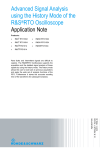
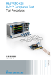
R&S®EMC32 EUT Monitoring with
R&S® Digital Oscilloscopes
Application Note
Products:
ı
R&S®RTO
ı
R&S®RTE
ı
R&S®RTM
ı
R&S®EMC32
O.Gerlach, J.Kuppe, Z.Saeed
4.2015 – 1MA242_2e
Application Note
This application note describes how to use the mask
and limit test features of the R&S®RTO, R&S®RTE
and R&S®RTM Digital Oscilloscopes for EUT
monitoring of signal forms, jitter etc. with the
R&S®EMC32 Measurement Software. The mask test
function allows autonomous characterization of
digital signal integrity during EMS tests.
R&S®EMC32 software records violations of userdefined limits or mask templates and evaluates the
immunity threshold at frequencies of critical
electromagnetic susceptibility.
Table of Contents
1 Overview .............................................................................................. 4
2 Hardware Configuration ..................................................................... 5
3 RTx Mask Test Functionality for EUT Monitoring ............................ 6
3.1
RTO / RTE Oscilloscope Settings ..............................................................................6
3.1.1
Test Definition ................................................................................................................6
3.1.2
Mask Definition ..............................................................................................................7
3.1.3
Event Actions / Reset ....................................................................................................8
3.1.4
Mask Display..................................................................................................................8
3.1.5
Test Examples ...............................................................................................................9
3.2
RTM Oscilloscope Settings ......................................................................................11
3.2.1
Test Definition ..............................................................................................................11
3.3
Device Setting in EMC32 ...........................................................................................13
3.3.1
Adding the Device to the Device List ...........................................................................13
3.4
EUT Monitoring Example ..........................................................................................20
3.4.1
Oscilloscope Monitoring Settings.................................................................................20
3.4.2
Actions .........................................................................................................................24
3.4.3
Start Test .....................................................................................................................24
4 RTO / RTE Limit Test Functionality for EUT Monitoring ................ 28
4.1
Amplitude Measurement ...........................................................................................29
4.1.1
Oscilloscope Settings ..................................................................................................29
4.2
Jitter Measurement ....................................................................................................33
4.2.1
Oscilloscope Settings ..................................................................................................33
4.3
EMC32 Settings ..........................................................................................................38
4.3.1
Adding the Device to the Device List ...........................................................................38
4.4
EUT Monitoring Example ..........................................................................................44
4.4.1
Oscilloscope Monitoring Settings .................................................................................44
4.4.2
Actions .........................................................................................................................47
4.4.3
Start Test .....................................................................................................................47
5 EMC32 Limit Testing......................................................................... 51
5.1
RMS Measurement .....................................................................................................51
5.1.1
Oscilloscope Settings ..................................................................................................51
5.2
EMC32 Settings ..........................................................................................................52
5.2.1
Adding the Device to the Device List ...........................................................................52
Table of Contents
5.3
EUT Monitoring Example ..........................................................................................57
5.3.1
Oscilloscope Monitoring Settings .................................................................................57
5.3.2
Actions .........................................................................................................................60
5.3.3
Start Test .....................................................................................................................60
6 Literature ........................................................................................... 64
7 Additional Information...................................................................... 65
8 Ordering Information ........................................................................ 66
1MA242_2e
Rohde & Schwarz R&S®EMC32 EUT Monitoring with R&S® Digital Oscilloscopes
3
Overview
RTO / RTE Oscilloscope Settings
1 Overview
This application note describes how to use the mask and limit test features of the
R&S®RTO, R&S®RTE and R&S®RTM Digital Oscilloscopes for EUT monitoring with
the R&S®EMC32 EMS Measurement Software. A mask test monitors the integrity of
digital signals while a limit test monitors a calculated value such as amplitudes (dB, A,
V, etc.), rise times, jitter, etc. As soon as a user-defined mask or limit is violated,
R&S®EMC32 records the violation and evaluates the immunity threshold at the current
frequency.
The following abbreviations are used in the following text for R&S® test equipment:
ı
ı
ı
ı
ı
ı
ı
ı
1MA242_2e
The R&S®EMC32 EMS Measurement Software for Conducted and Radiated
Susceptibility is referred to as EMC32. The R&S®EMC32-S Software for immunity
basic measurements is referred to as EMC32-S.
The R&S®RTE1022, R&S®RTE1024, R&S®RTE1032, R&S®RTE1034,
R&S®RTE1052, R&S®RTE1054, R&S®RTE1102, R&S®RTE1104 Digital
Oscilloscopes are referred to as RTE.
The R&S®RTO1002, R&S®RTO1004, R&S®RTO1012, R&S®RTO1014,
R&S®RTO1022, R&S®RTO1024, R&S®RTO1044 Digital Oscilloscopes are
referred to as RTO.
The R&S®RTM2032, R&S®RTM2034, R&S®RTM2052, R&S®RTM2054 Digital
Oscilloscopes are referred to as RTM.
Digital Oscilloscopes RTO, RTE and RTM are referred to as RTx.
The R&S®SMB100A Signal Generator is referred to as SMB.
The R&S®BBA100 Power Amplifier is referred to as BBA100.
R&S® stands for Rohde & Schwarz GmbH & Co KG.
Rohde & Schwarz R&S®EMC32 EUT Monitoring with R&S® Digital Oscilloscopes
4
Hardware Configuration
RTO / RTE Oscilloscope Settings
2 Hardware Configuration
Fig. 2-1 shows a typical conducted EMS test environment, consisting of an
oscilloscope (RTO, RTE or RTM), connected via a LAN interface to a PC that runs
EMC32-S software, an SMB signal generator and a BBA100 power amplifier according
to IEC/EN 61000-4-6 to monitor a defined EUT test point with the RTO / RTE / RTM
mask or RTO / RTE limit test feature.
LAN
SMB100A +
BBA100
power amp
RF
CDN
EUT
AC
Mains
Test
Point
Shielded Room
PC with EMC32
RTO
Fig. 2-1: Typical CDN setup for conducted EMS measurements according to IEC/EN 61000-4-6
The RTE / RTO requires firmware V2.30.1.0 or higher, the RTM V05.400 or higher.
1MA242_2e
Rohde & Schwarz R&S®EMC32 EUT Monitoring with R&S® Digital Oscilloscopes
5
RTx Mask Test Functionality for EUT Monitoring
RTO / RTE Oscilloscope Settings
3 RTx Mask Test Functionality for EUT
Monitoring
The mask test feature of the RTO, RTE and RTM oscilloscopes allows to define a
“masked” area around a signal (including uncertainties) taken from a relevant test point
on the EUT.
Fig. 3-1: Pulsed signal with masked area
During an EMS measurement the EUT is exposed to conducted and radiated
interferers, which may have an effect on the signal at the test point. These
measurements are usually unattended and therefore require automatic monitoring. The
RTO / RTE / RTM mask test will notify the EMC32 software immediately in case the
signal violated the mask and will also transmit the current interferer frequency.
3.1 RTO / RTE Oscilloscope Settings
A mask can be created by selecting the M ASKS button on the front panel of the RTO or
RTE and setting the parameters in the dialog boxes TEST DEFINITION, M ASK DEFINITION,
EVEN ACTION / RESET, M ASK DISPLAY.
3.1.1 Test Definition
The following parameters shall be used:
Enable test: Enable / disable the mask test by clicking on this soft-key.
Definition type: If WAVEFORM is selected, a mask is created from an existing
waveform. A given offset from the waveform builds the upper and lower limit lines of
the mask, limits that can be moved and stretched. The result is a tolerance tube
around the waveform used as mask.
Fail condition, Violation tolerance: The fail criteria for a mask test are set by two
parameters: "Fail condition" and "Violation tolerance".
1MA242_2e
Rohde & Schwarz R&S®EMC32 EUT Monitoring with R&S® Digital Oscilloscopes
6
RTx Mask Test Functionality for EUT Monitoring
RTO / RTE Oscilloscope Settings
"Fail condition" defines the kind of hits to be considered for test evaluation:
ı
SAMPLES: Number of samples (VIOLATION TOLERANCE) that hit the mask.
ı
ACQUISITIONS: Number of acquisitions (VIOLATION TOLERANCE) that contain at least
one sample hitting the mask.
Fig. 3-2: RTO “Test Definition” Tab
3.1.2 Mask Definition
DEFINITION TYPE: Select WAVEFORM to create a mask from an existing waveform.
HORIZONTAL WIDTH: Sets the mask width (div).
VERTICAL WIDTH: Sets the mask height (div).
CREATE MASK: Creates the upper and lower mask limit from the selected reference
waveform. If the reference waveform was not defined before, it is created automatically
from the SOURCE waveform, which is selected in the TEST DEFINITION tab.
Fig. 3-3: RTO “Mask Definition” Tab
1MA242_2e
Rohde & Schwarz R&S®EMC32 EUT Monitoring with R&S® Digital Oscilloscopes
7
RTx Mask Test Functionality for EUT Monitoring
RTO / RTE Oscilloscope Settings
3.1.3 Event Actions / Reset
This tab defines, which actions shall be taken in case the mask was violated or not.
Most actions can be initiated either on violation or pass:
ON VIOLATION: The parameter STOP ACQ is set to ON VIOLATION in the EVENT ACTIONS /
RESET tab. This action will be initiated (thus, the acquisition of samples will be stopped)
as soon as the signal violates the mask and the fail criteria are fulfilled.
Fig. 3-4: RTO / RTE “Event Actions / Reset” Tab
3.1.4 Mask Display
The M ASK DISPLAY tab contains all settings for mask and hit display. Different colors
can be assigned to the actions for better readability.
Fig. 3-5: RTO / RTE “Mask Display” Tab
1MA242_2e
Rohde & Schwarz R&S®EMC32 EUT Monitoring with R&S® Digital Oscilloscopes
8
RTx Mask Test Functionality for EUT Monitoring
RTO / RTE Oscilloscope Settings
3.1.5 Test Examples
The following example shows a signal that does not violate the mask.
Fig. 3-6: Test Example without mask violation
Fail Criteria “Samples”:
This test has failed because 10 or more samples have violated the mask.
Fig. 3-7: Test example with fail criteria “Samples”
1MA242_2e
Rohde & Schwarz R&S®EMC32 EUT Monitoring with R&S® Digital Oscilloscopes
9
RTx Mask Test Functionality for EUT Monitoring
RTO / RTE Oscilloscope Settings
Fail Criteria “Acquisition”:
This example test failed because the 7th acquisition violated the mask with at least one
sample.
Fig. 3-8: Test example with fail criteria “Acquisition”
1MA242_2e
Rohde & Schwarz R&S®EMC32 EUT Monitoring with R&S® Digital Oscilloscopes
10
RTx Mask Test Functionality for EUT Monitoring
RTM Oscilloscope Settings
3.2 RTM Oscilloscope Settings
A mask can be created by selecting the TOOLS button, then the M ASK TEST soft key.
3.2.1 Test Definition
The following parameters shall be used:
Test – Enable / disable the mask test by clicking on this soft-key.
New Mask → COPY CHANNEL – Generates a mask surrounding the original waveform.
Use Y-Position, Stretch Y, Width Y and Width X to define a custom mask area. Press
Save to store the custom mask.
Fig. 3-9: RTM New Mask
ACTIONS – Defines which events will be initiated in case the mask is violated:
ı
SOUND – Alarm can be turned OFF, go off after each violation or after n mask
violations.
ı
STOP – Mask test can continue or be stopped after one or n mask violations.
ı
SCREENSHOT – No screenshot, or one screenshot after each or n mask violations.
ı
PRINT – Print waveform data after each or n violations.
ı
WAVEFORM – Save waveform after each or n violations.
ı
PULSE – Turn ON custom pulse at trigger output after each or n violations.
Fig. 3-10: RTM Mask Test Actions
1MA242_2e
Rohde & Schwarz R&S®EMC32 EUT Monitoring with R&S® Digital Oscilloscopes
11
RTx Mask Test Functionality for EUT Monitoring
RTM Oscilloscope Settings
The figure below shows an example mask test of a pulse curve.
Fig. 3-11: Mask Test running on RTM Oscilloscope
1MA242_2e
Rohde & Schwarz R&S®EMC32 EUT Monitoring with R&S® Digital Oscilloscopes
12
RTx Mask Test Functionality for EUT Monitoring
Device Setting in EMC32
3.3 Device Setting in EMC32
3.3.1 Adding the Device to the Device List
The configuration is done in the Device List, which is accessible via the menu
EXTRAS –> DEVICE LIST …
Fig. 3-12: Opening the Device List
or with the function key shortcut “F9”
or via the Device List icon
1MA242_2e
Rohde & Schwarz R&S®EMC32 EUT Monitoring with R&S® Digital Oscilloscopes
13
RTx Mask Test Functionality for EUT Monitoring
Device Setting in EMC32
Add the GENERIC MONITORING device to the right side of the DEVICE LIST as
CONFIGURED DEVICE.
Fig. 3-13: “Generic Monitoring” device added to “Configured Devices”
Single click on the entry and rename GENERIC MONITORING to an appropriate Device
Name, e.g. RTO TEST M ASK (or RTE / RTM).
Fig. 3-14: Rename “Generic Monitoring” to “RTO Test Mask”
Note: Please make sure that all necessary instrument drivers, e.g. SMB, NRP-Zxx
have been installed, before running an EMS test. If some or all devices are missing, a
message box allowing simulation mode enabling will appear.
1MA242_2e
Rohde & Schwarz R&S®EMC32 EUT Monitoring with R&S® Digital Oscilloscopes
14
RTx Mask Test Functionality for EUT Monitoring
Device Setting in EMC32
3.3.1.1 Generic Monitoring Properties
Edit the RTO / RTE / RTM Test Mask properties by double clicking on the menu item. It
is defined by six properties:
ı
General
ı
Interface Parameters
ı
General Commands
ı
Device Programming
ı
Measurement Queries
ı
EMS Information
3.3.1.2 General and Interface Parameters Tabs
In the General tab, select the appropriate INTERFACE TYPE from a list of addresses or
by using the VISA DEVICE IDENTIFIER (see Fig. 3-15).
After editing this parameter, close the RTO / RTE / RTM Mask Test window by
pressing OK. Also close the Device List by pressing OK. If there have been significant
changes in the Device List, a window pops up, advising to close and restart EMC32-S.
Re-open the Device List and activate the RTO TEST MASK (or RTE / RTM) device by
changing the STATE from VIRTUAL to PHYSICAL.
Fig. 3-15: Select Interface Type “VISA”
1MA242_2e
Rohde & Schwarz R&S®EMC32 EUT Monitoring with R&S® Digital Oscilloscopes
15
RTx Mask Test Functionality for EUT Monitoring
Device Setting in EMC32
First Step
Second Step
Fig. 3-16: Set State to “Physical”
Change to INTERFACE PARAMETERS tab and set the parameters.
Fig. 3-17: Import settings
Import parameters by clicking IMPORT SETTINGS.
In the newly opened dialog box Import Settings, select predefined parameters by
clicking the
1MA242_2e
button, selecting RTO / RTE / RTM MASK TEST and pressing OK.
Rohde & Schwarz R&S®EMC32 EUT Monitoring with R&S® Digital Oscilloscopes
16
RTx Mask Test Functionality for EUT Monitoring
Device Setting in EMC32
Fig. 3-18: Select “RTO Mask Test” configuration file, same for RTE/RTM
After pressing OK, the RTO / RTE / RTM Mask Test configuration file will be displayed
in the IMPORT SETTINGS dialog.
Fig. 3-19: Configuration File to Import
Click on IMPORT to load the configuration. The import is completed by pressing OK on
the following message window.
Fig. 3-20: Successful file import
The RTO / RTE / RTM Mask Test import file contains following lines.
1MA242_2e
Rohde & Schwarz R&S®EMC32 EUT Monitoring with R&S® Digital Oscilloscopes
17
RTx Mask Test Functionality for EUT Monitoring
Device Setting in EMC32
3.3.1.3 General Commands
Commands for the basic configuration of the monitoring device are defined in this tab.
The following commands are available:
Fig. 3-21: Generic Monitoring Commands
3.3.1.4 Device Programming
This tab is not used in this context and therefore skipped here.
3.3.1.5 Measurement Queries
This tab contains the SCPI command for executing a Mask Test measurement and
reading the result.
Fig. 3-22: “Measurement Queries” tab with Mask Test Result SCPI command
3.3.1.6 EMS Information
This tab is not used and therefore left empty. However, you have to press the
button in this dialog window, to get to the GENERIC MONITORING test dialog.
1MA242_2e
Rohde & Schwarz R&S®EMC32 EUT Monitoring with R&S® Digital Oscilloscopes
18
RTx Mask Test Functionality for EUT Monitoring
Device Setting in EMC32
3.3.1.7 Generic Monitoring Test Dialog
After pressing the
button in the EMS INFORMATION tab, the following dialog
box will be opened, allowing to select an item from the GENERAL COMMANDS or
MEASUREMENT QUERIES list. Select IDENTIFICATION QUERY from the GENERAL
COMMANDS and enter the TEST COMMAND “*IDN?”. After pressing TEST COMMAND, the
command is sent to the oscilloscope and the response (RTO / RTE / RTM ID string) is
received. Then, exit this dialog by pressing CLOSE.
Fig. 3-23: Generic Monitoring Test Dialog
1MA242_2e
Rohde & Schwarz R&S®EMC32 EUT Monitoring with R&S® Digital Oscilloscopes
19
RTx Mask Test Functionality for EUT Monitoring
EUT Monitoring Example
3.4 EUT Monitoring Example
In order to perform the example, a test template for EUT monitoring with an RTO / RTE
/ RTM oscilloscope is required first.
3.4.1 Oscilloscope Monitoring Settings
To generate a new EUT Monitoring Test Template, proceed as shown in Fig. 3-23.
Fig. 3-24: EUT Monitoring Configuration: “New File”
In the EMC32 Explorer, select FILE –> TEST TEMPLATE OPEN/NEW…. Right-click on the
EUT MONITORING menu item and select NEW FILE. A new window for configuring the
RTO TEST M ASK (or RTE / RTM) parameters pops up.
Fig. 3-25: EUT Monitoring configuration: RTx Test Mask selection
1MA242_2e
Rohde & Schwarz R&S®EMC32 EUT Monitoring with R&S® Digital Oscilloscopes
20
RTx Mask Test Functionality for EUT Monitoring
EUT Monitoring Example
Right-click on the oscilloscope device icon in the HARDWARE tab and select RTO TEST
M ASK (or RTE / RTM) from the list.
Fig. 3-26: EUT Monitoring Configuration: Selected Device
Then (left-) click on the icon to configure the device in the following pop-up window,
according to Fig. 3-26: select “Send Trigger Command”, and specify the Measurement
Query as “Get Result”.
.
Fig. 3-27: EUT Monitoring Configuration: Device Settings
1MA242_2e
Rohde & Schwarz R&S®EMC32 EUT Monitoring with R&S® Digital Oscilloscopes
21
RTx Mask Test Functionality for EUT Monitoring
EUT Monitoring Example
Press OK to complete the RTO / RTE / RTM Test Mask configuration, which appears
in the EUT Monitoring configuration in Fig. 3-27.
Fig. 3-28: EUT Monitoring Configuration
After configuring RTO TEST M ASK (or RTE / RTM) go to the CHANNEL tab and select
TRIGGER MODE –> BEFORE DWELL.
Fig. 3-29: EUT Monitoring Configuration: “Trigger Mode” Selection
In the NOGO tab, set NOGO TYPE to ABOVE LIMIT, set LIMIT VALUE = 0.50000 and press
OK to save the RTO M ASK TEST (or RTE / RTM) configuration.
1MA242_2e
Rohde & Schwarz R&S®EMC32 EUT Monitoring with R&S® Digital Oscilloscopes
22
RTx Mask Test Functionality for EUT Monitoring
EUT Monitoring Example
Fig. 3-30: EUT Monitoring Configuration: “Limit Value”
1MA242_2e
Rohde & Schwarz R&S®EMC32 EUT Monitoring with R&S® Digital Oscilloscopes
23
RTx Mask Test Functionality for EUT Monitoring
EUT Monitoring Example
3.4.2 Actions
If the measurement should be stopped after a limit violation occurred, add STOP TEST
to the ACTION ON NOGO item.
Fig. 3-31: Action on NoGo –> Stop Test
3.4.3 Start Test
Download DEVICECONFIGURATION_FILES.ZIP from the 1MA242 application note page and
unzip EUT TEST.EMSCONFIGURATION to <EMC32 DIRECTORY>\EMC32\SYSTEM\TEST
TEMPLATES\EMS SCAN\EN61000-4-3\.and RTO M ASK TEST.EUTCONFIGURATION , RTE
M ASK TEST.* and RTM M ASK TEST.* to <EMC32 DIRECTORY>\EMC32\SYSTEM\TEST
TEMPLATES\EUT MONITORING\.
Note: In case of Windows7 and the default data directory C:\PROGRAMDATA it is
necessary to make it visible first by unchecking the HIDE PROTECTED OPERATING FILES
in the FOLDER OPTIONS.
In the EMC32 Explorer, right-click on the menu item TEST TEMPLATE –> EMS SCAN –>
EN61000-4-3 (EMS Radiated) –> EUT TEST and select NEW TEST.
Fig. 3-32: Start EMS Scan Test Template as New Test
A NEW TEST window with EMS Radiated specific default parameters pops up.
1MA242_2e
Rohde & Schwarz R&S®EMC32 EUT Monitoring with R&S® Digital Oscilloscopes
24
RTx Mask Test Functionality for EUT Monitoring
EUT Monitoring Example
Fig. 3-33: New Test dialog
After pressing the EUT MONITORING PARAMETERS –>
icon, the EuT Monitoring
Open window pops up, which allows to select RTO MASK TEST (or RTE / RTM).
Fig. 3-34: EUT monitoring File location
1MA242_2e
Rohde & Schwarz R&S®EMC32 EUT Monitoring with R&S® Digital Oscilloscopes
25
RTx Mask Test Functionality for EUT Monitoring
EUT Monitoring Example
Fig. 3-35: New Test dialog with “RTO Mask Test”
After pressing OK, the test is ready for execution.
Fig. 3-36: EMC32 Test Execution
1MA242_2e
Rohde & Schwarz R&S®EMC32 EUT Monitoring with R&S® Digital Oscilloscopes
26
RTx Mask Test Functionality for EUT Monitoring
EUT Monitoring Example
The upper graph in Fig. 3-35 (see also Fig. 3-36) shows how the Mask value jumps
from 0 to 1 when the signal violates the test mask. With logical units (0 and 1) rather
than a physical scale, any Mask value of 1 exceeds the pre-defined 0.5 limit line, thus
rendering a FAIL result.
Fig. 3-37: EMC32 test execution
1MA242_2e
Rohde & Schwarz R&S®EMC32 EUT Monitoring with R&S® Digital Oscilloscopes
27
RTO / RTE Limit Test Functionality for EUT Monitoring
EUT Monitoring Example
4 RTO / RTE Limit Test Functionality for EUT
Monitoring
RTO / RTE oscilloscopes offer a wide range of measurement functions that are
suitable for EUT monitoring tests. The measurement functions are divided in
ı
AMP/TIME – Amplitude, Peak to peak, Mean, RMS, etc.
Fig. 4-1: RTO / RTE Amplitude and Time Measurement Functions
ı
1MA242_2e
JITTER – Period, Frequency, Cycle jitter, skew delay, etc.
Rohde & Schwarz R&S®EMC32 EUT Monitoring with R&S® Digital Oscilloscopes
28
RTO / RTE Limit Test Functionality for EUT Monitoring
Amplitude Measurement
ı
EYE – Extinction ratio (%), Q factor, Noise (RMS), S/N Ratio etc.
ı
HISTOGRAM – Histogram peak, Mean, Standard Deviation, etc.
Some measurement groups are only accessible with the according option (see RTO /
RTE manual for more details on available options).
4.1 Amplitude Measurement
The first example will focus on an amplitude measurement, using the oscilloscope as
a EUT monitoring device in EMC32.
A 100 kHz sine signal (-10 dBm) from any signal generator is fed into Channel 1 of the
RTO / RTE.
4.1.1 Oscilloscope Settings
1MA242_2e
ı
Press PRESET on the RTO / RTE to obtain a defined initial state.
ı
Press AUTOSET for optimized display.
Rohde & Schwarz R&S®EMC32 EUT Monitoring with R&S® Digital Oscilloscopes
29
RTO / RTE Limit Test Functionality for EUT Monitoring
Amplitude Measurement
Fig. 4-1: The display shows an auto-triggered and auto-scaled measurement of amplitude over time
The peak-to-peak amplitude is approx. 440 mV.
ı
Select MEAS –> SETUP in the RTO / RTE menu.
Fig. 4-2: Selecting the Setup dialog from the Measurement menu
1MA242_2e
ı
Activate MEAS 1 STATE
ı
Select the AMP/TIME tab
ı
Turn the Limit Check on by selecting LIMIT ONLY
Rohde & Schwarz R&S®EMC32 EUT Monitoring with R&S® Digital Oscilloscopes
30
RTO / RTE Limit Test Functionality for EUT Monitoring
Amplitude Measurement
Fig. 4-3: Configuring the Setup dialog within the Measurement menu
ı
Close the MEAS dialog to read an actual amplitude measurement value.
Fig. 4-4: Here, the measured amplitude value is 426.09 mV
ı
Select MEAS –> SETUP, again
ı
Enter appropriate upper and lower limit values that come close to the measured
value, e.g. 426.1 mV and 426.0 mV
Fig. 4-5: Enter the upper and lower limit by double clicking on the values
If the amplitude exceeds the upper or lower limit, an alarm will be set. The amplitude
measurement is now active.
To verify the measurement activity, the oscilloscope can be made to beep upon limit
violation.
1MA242_2e
Rohde & Schwarz R&S®EMC32 EUT Monitoring with R&S® Digital Oscilloscopes
31
RTO / RTE Limit Test Functionality for EUT Monitoring
Amplitude Measurement
ı
Select MEAS –> EVENT ACTIONS in the RTO / RTE menu.
Fig. 4-6: Selecting the Event Actions dialog from the Measurement menu
Fig. 4-7: In the Event Actions dialog, select Beep -> On violation
To monitor the measurement, proceed with chapter 4.3 on EMC32 settings.
1MA242_2e
Rohde & Schwarz R&S®EMC32 EUT Monitoring with R&S® Digital Oscilloscopes
32
RTO / RTE Limit Test Functionality for EUT Monitoring
Jitter Measurement
4.2 Jitter Measurement
The next example will focus on a measurement of jitter (periodicity deviations, or
phase noise) and show how to define it in the RTO / RTE and as EUT monitoring
device in EMC32.
Again, a 100 kHz sine signal (-10 dBm) is fed into Channel 1 of the RTO / RTE.
4.2.1 Oscilloscope Settings
ı
Press PRESET on the RTO / RTE to obtain a defined initial state.
ı
Press AUTOSET for optimized display.
ı
Select MEAS –> SETUP in the RTO / RTE menu.
Fig. 4-8: Selecting the Setup dialog from the Measurement menu
ı
Select the JITTER tab
Fig. 4-9: It is convenient to use the Jitter Wizard for defining the test, as this will guide you to the
measurement with just three more clicks
1MA242_2e
Rohde & Schwarz R&S®EMC32 EUT Monitoring with R&S® Digital Oscilloscopes
33
RTO / RTE Limit Test Functionality for EUT Monitoring
Jitter Measurement
Fig. 4-10: Select a period and frequency measurement in the Jitter Wizard
Fig. 4-11: Confirm the pre-selection of Channel 1 by clicking “Next”
1MA242_2e
Rohde & Schwarz R&S®EMC32 EUT Monitoring with R&S® Digital Oscilloscopes
34
RTO / RTE Limit Test Functionality for EUT Monitoring
Jitter Measurement
Fig. 4-12: Confirm automatic scaling and auto reference levels by clicking “Next”
Fig. 4-13: Start the Jitter measurement with all the four suggested plot types by pressing “Execute”
1MA242_2e
Rohde & Schwarz R&S®EMC32 EUT Monitoring with R&S® Digital Oscilloscopes
35
RTO / RTE Limit Test Functionality for EUT Monitoring
Jitter Measurement
Fig. 4-14:Measurement results showing the period near 10 µs and the corresponding frequency near
100 kHz. The histogram in the lowest measurement window gives indication of the presence of some
jitter
ı
Select MEAS –> SETUP in the RTO / RTE menu.
Fig. 4-15: In the Setup dialog, select Limit Check
1MA242_2e
Rohde & Schwarz R&S®EMC32 EUT Monitoring with R&S® Digital Oscilloscopes
36
RTO / RTE Limit Test Functionality for EUT Monitoring
Jitter Measurement
Fig. 4-16: Turn the Limit Check on by selecting Limit Only
The pulse frequency of f = 100 kHz corresponds to a pulse repetition period of
T = 1/f = 10 µs. In order to measure jitter, it must be made sure that any small deviation
(e.g., ±0.01 µs) from the 10 µs pulse period is detected.
Therefore, in the setup dialog, define the upper and lower limit of the period to be
10.01 µs and 9.99 µs, according to Fig. 4-17.
Fig. 4-17: Enter the upper and lower limit by double clicking on the values
If the period exceeds the upper or lower limit, an alarm will be set. The jitter
measurement is now active.
To verify the measurement activity, the oscilloscope can be made to beep upon limit
violation.
ı
Select MEAS –> EVENT ACTIONS in the RTO / RTE menu.
Fig. 4-18: Selecting the Event Actions dialog from the Measurement menu
1MA242_2e
Rohde & Schwarz R&S®EMC32 EUT Monitoring with R&S® Digital Oscilloscopes
37
RTO / RTE Limit Test Functionality for EUT Monitoring
EMC32 Settings
Fig. 4-19: Select Beep –> On violation
4.3 EMC32 Settings
4.3.1 Adding the Device to the Device List
The configuration is done in the Device List, which is accessible via the menu
EXTRAS –> DEVICE LIST …
Fig. 4-2: Opening the Device List
or with the function key shortcut “F9”
or via the Device List icon
1MA242_2e
Rohde & Schwarz R&S®EMC32 EUT Monitoring with R&S® Digital Oscilloscopes
38
RTO / RTE Limit Test Functionality for EUT Monitoring
EMC32 Settings
Add the GENERIC MONITORING device to the right side of the DEVICE LIST as
CONFIGURED DEVICE.
Fig. 4-3: “Generic Monitoring” device added to “Configured Devices”
Single click on the entry and rename GENERIC MONITORING to an appropriate Device
Name, e.g. RTO TEST LIMIT.
Fig. 4-4: Rename “Generic Monitoring” to “RTO Test Limit”
Note: Please make sure that all necessary instrument drivers, e.g. SMB, NRP-Zxx
have been installed, before running an EMS test. If some or all devices are missing, a
message box allowing simulation mode enabling will appear.
1MA242_2e
Rohde & Schwarz R&S®EMC32 EUT Monitoring with R&S® Digital Oscilloscopes
39
RTO / RTE Limit Test Functionality for EUT Monitoring
EMC32 Settings
4.3.1.1 Generic Monitoring Properties
Edit the RTO TEST LIMIT properties by double clicking on the menu item. It is defined by
six properties:
ı
General
ı
Interface Parameters
ı
General Commands
ı
Device Programming
ı
Measurement Queries
ı
EMS Information
4.3.1.2 General and Interface Parameters Tabs
In the General tab, select the appropriate INTERFACE TYPE from a list of addresses or
by using the VISA DEVICE IDENTIFIER (see Fig. 4-5).
After editing this parameter, close the RTO Limit Test window by pressing OK. Also
close the Device List by pressing OK. If there have been significant changes in the
Device List, a window pops up, advising to close and restart EMC32-S. Re-open the
Device List and activate the RTO Test Limit device by changing the STATE from
VIRTUAL to PHYSICAL.
Fig. 4-5: Select Interface Type “VISA”
1MA242_2e
Rohde & Schwarz R&S®EMC32 EUT Monitoring with R&S® Digital Oscilloscopes
40
RTO / RTE Limit Test Functionality for EUT Monitoring
EMC32 Settings
First Step
Second Step
Fig. 4-6: Set State to “Physical”
Change to INTERFACE PARAMETERS tab and set the parameters.
Fig. 4-7: Import settings
Import parameters by clicking IMPORT SETTINGS.
In the newly opened dialog box Import Settings, select predefined parameters by
clicking the
1MA242_2e
button, selecting RTO LIMIT TEST and pressing OK.
Rohde & Schwarz R&S®EMC32 EUT Monitoring with R&S® Digital Oscilloscopes
41
RTO / RTE Limit Test Functionality for EUT Monitoring
EMC32 Settings
Fig. 4-8: Configuration File to Import
Click on IMPORT to load the configuration. The import is completed by pressing OK on
the following message window.
Fig. 4-9: Successful file import
The RTO Limit Test import file contains following lines.
4.3.1.3 General Commands
Commands for the basic configuration of the monitoring device are defined in this tab.
The following commands are available:
Fig. 4-10: Generic Monitoring Commands
1MA242_2e
Rohde & Schwarz R&S®EMC32 EUT Monitoring with R&S® Digital Oscilloscopes
42
RTO / RTE Limit Test Functionality for EUT Monitoring
EMC32 Settings
4.3.1.4 Device Programming
This tab contains two commands for activating the limit test.
Fig. 4-11: Commands for activating Limit Test
4.3.1.5 Measurement Queries
This tab contains the Limit Test Result (0=PASS, 1=FAIL).
Fig. 4-12: “Measurement Queries” tab with Status Byte Query
4.3.1.6 Generic Monitoring Test Dialog
After pressing the
button in the EMS INFORMATION tab, the following dialog
box will be opened, allowing to select an item from the GENERAL COMMANDS or
MEASUREMENT QUERIES list. Select IDENTIFICATION QUERY from the GENERAL
COMMANDS and enter the TEST COMMAND “*IDN?”. After pressing TEST COMMAND, the
command is sent to the oscilloscope and the response (RTO ID string) is received.
Then, exit this dialog by pressing CLOSE.
Fig. 4-13: Generic Monitoring Test Dialog
1MA242_2e
Rohde & Schwarz R&S®EMC32 EUT Monitoring with R&S® Digital Oscilloscopes
43
RTO / RTE Limit Test Functionality for EUT Monitoring
EUT Monitoring Example
4.4 EUT Monitoring Example
In order to perform the example, a test template for EUT monitoring with an RTO or
RTE oscilloscope is required first.
4.4.1 Oscilloscope Monitoring Settings
To generate a new EUT Monitoring Test Template, proceed as shown in Fig. 4-14.
Fig. 4-14: EUT Monitoring Configuration: “New File”
In the EMC32 Explorer, select File –> Test Template open/new. Right-click on the EUT
MONITORING menu item and select NEW FILE. A new window for configuring the RTO
Test Limit parameters pops up.
1MA242_2e
Rohde & Schwarz R&S®EMC32 EUT Monitoring with R&S® Digital Oscilloscopes
44
RTO / RTE Limit Test Functionality for EUT Monitoring
EUT Monitoring Example
Fig. 4-15: EUT Monitoring configuration: RTO Test Limit selection
Right-click on the oscilloscope device icon in the HARDWARE tab and select RTO TEST
LIMIT from the list.
Fig. 4-16: EUT Monitoring Configuration: Selected Device
Then left-click on the icon to configure the device in the following pop-up window,
according to Fig. 4-17: select “Send Trigger Command”, and specify the Measurement
Query as “Get Result”. Check the DEVICE PROGRAMMING items POSITIVE TRANSITION…
and ENABLE LIMIT FUNCTION.
.
1MA242_2e
Rohde & Schwarz R&S®EMC32 EUT Monitoring with R&S® Digital Oscilloscopes
45
RTO / RTE Limit Test Functionality for EUT Monitoring
EUT Monitoring Example
Fig. 4-17: EUT Monitoring Configuration: Device Settings
Press OK to complete the RTO TEST LIMIT configuration, which appears in the EUT
Monitoring configuration in Fig. 4-18.
Fig. 4-18: EUT Monitoring Configuration
After configuring RTO TEST LIMIT, go to the CHANNEL tab and select TRIGGER MODE –>
BEFORE DWELL.
Fig. 4-19: EUT Monitoring Configuration: “Trigger Mode” Selection
1MA242_2e
Rohde & Schwarz R&S®EMC32 EUT Monitoring with R&S® Digital Oscilloscopes
46
RTO / RTE Limit Test Functionality for EUT Monitoring
EUT Monitoring Example
In the NOGO tab, set NOGO TYPE to ABOVE LIMIT, set LIMIT VALUE = 0.50000 and press
OK to save the RTO LIMIT TEST configuration.
Fig. 4-20: EUT Monitoring Configuration: “Limit Value”
4.4.2 Actions
If the measurement should be stopped after a limit violation occurred, add STOP TEST
to the ACTION ON NOGO item.
Fig. 4-21: Action on NoGo → Stop Test
4.4.3 Start Test
Download DEVICECONFIGURATION_FILES.ZIP from the 1MA242 application note page and
unzip EUT TEST.EMSCONFIGURATION to <EMC32 DIRECTORY>\EMC32\SYSTEM\TEST
TEMPLATES\EMS SCAN\EN61000-4-3\ and RTO LIMIT TEST.EUTCONFIGURATION , RTE
LIMIT TEST.* to <EMC32 DIRECTORY>\EMC32\SYSTEM\TEST TEMPLATES\EUT
MONITORING\.
Note: In case of Windows7 and the default data directory C:\PROGRAMDATA it is
necessary to make it visible first by unchecking the HIDE PROTECTED OPERATING FILES
in the FOLDER OPTIONS.
In the EMC32 Explorer, right-click on the menu item TEST TEMPLATE –> EMS SCAN –>
EN61000-4-3 (EMS Radiated) –> EUT TEST and select NEW TEST.
Note: In case of Windows7 and the default data directory C:\PROGRAMDATA it is
necessary to make it visible first by unchecking the HIDE PROTECTED OPERATING FILES
in the FOLDER OPTIONS).
In the EMC32 Explorer, right-click on the menu item TEST TEMPLATE –> EMS SCAN –>
EN61000-4-3 (EMS Radiated) –> EUT TEST and select NEW TEST.
1MA242_2e
Rohde & Schwarz R&S®EMC32 EUT Monitoring with R&S® Digital Oscilloscopes
47
RTO / RTE Limit Test Functionality for EUT Monitoring
EUT Monitoring Example
Fig. 4-22: Start EMS Scan Test Template as New Test
A NEW TEST window with EMS Radiated specific default parameters pops up.
Fig. 4-23: New Test dialog
After pressing the EUT MONITORING PARAMETERS –>
icon, the EuT Monitoring
Open window pops up, which allows to select the RTO LIMIT TEST(.EUTConfiguration).
1MA242_2e
Rohde & Schwarz R&S®EMC32 EUT Monitoring with R&S® Digital Oscilloscopes
48
RTO / RTE Limit Test Functionality for EUT Monitoring
EUT Monitoring Example
Fig. 4-24: EUT monitoring File location
Fig. 4-25: New Test dialog with “RTO Limit Test”
After pressing OK, the test is ready for execution.
Fig. 4-26: EMC32 Test Execution
The upper graph in Fig. 4-26 (see also Fig. 4-27) shows how the Limit value jumps
from 0 to 1 when the signal violates the limit. The logical units 0 and 1 are interpreted
as 0.0 and 1.0 which exceeds the pre-defined 0.5 limit line, causing a FAIL result.
1MA242_2e
Rohde & Schwarz R&S®EMC32 EUT Monitoring with R&S® Digital Oscilloscopes
49
RTO / RTE Limit Test Functionality for EUT Monitoring
EUT Monitoring Example
Fig. 4-27: EUT Channel 1 measurement result
1MA242_2e
Rohde & Schwarz R&S®EMC32 EUT Monitoring with R&S® Digital Oscilloscopes
50
EMC32 Limit Testing
RMS Measurement
5 EMC32 Limit Testing
In case an instrument does not have the limit test capability, e.g. RTM, EMC32 can
handle the limit checking instead. The performance will slightly be reduced as
compared to use of RTO / RTE.
5.1 RMS Measurement
This example shows how to set up the RTM oscilloscope for an RMS measurement
and configure EMC32 to stop the measurement in case the RMS value drops below a
certain limit.
5.1.1 Oscilloscope Settings
Press the MEAS button and select MEAS. TYPE, e.g. RMS. Connect the pulse output
with CH1 input via probe and press AUTOSET.
Fig. 5-1: RMS Measurement on RTM
1MA242_2e
Rohde & Schwarz R&S®EMC32 EUT Monitoring with R&S® Digital Oscilloscopes
51
EMC32 Limit Testing
EMC32 Settings
5.2 EMC32 Settings
5.2.1 Adding the Device to the Device List
The configuration is done in the Device List, which is accessible via the menu
EXTRAS –> DEVICE LIST …
Fig. 5-2: Opening the Device List
or with the function key shortcut “F9”
or via the Device List icon
1MA242_2e
Rohde & Schwarz R&S®EMC32 EUT Monitoring with R&S® Digital Oscilloscopes
52
EMC32 Limit Testing
EMC32 Settings
Add the GENERIC MONITORING device to the right side of the DEVICE LIST as
CONFIGURED DEVICE.
Fig. 5-3: “Generic Monitoring” device added to “Configured Devices”
Single click on the entry and rename GENERIC MONITORING to an appropriate Device
Name, e.g. RTM TEST LIMIT.
Fig. 5-4: Rename “Generic Monitoring” to “RTM Test Limit”
Note: Please make sure that all necessary instrument drivers, e.g. SMB, NRP-Zxx
have been installed, before running an EMS test. If some or all devices are missing, a
message box allowing simulation mode enabling will appear.
1MA242_2e
Rohde & Schwarz R&S®EMC32 EUT Monitoring with R&S® Digital Oscilloscopes
53
EMC32 Limit Testing
EMC32 Settings
5.2.1.1 Generic Monitoring Properties
Edit the RTM TEST LIMIT properties by double clicking on the menu item. It is defined
by six properties:
ı
General
ı
Interface Parameters
ı
General Commands
ı
Device Programming
ı
Measurement Queries
5.2.1.2 General and Interface Parameters Tabs
In the General tab, select the appropriate INTERFACE TYPE from a list of addresses or
by using the VISA DEVICE IDENTIFIER (see Fig. 4-6).
After editing this parameter, close the RTM Limit Test window by pressing OK. Also
close the Device List by pressing OK. If there have been significant changes in the
Device List, a window pops up, advising to close and restart EMC32-S. Re-open the
Device List and activate the RTM Test Limit device by changing the STATE from
VIRTUAL to PHYSICAL.
First Step
Second Step
Fig. 5-5: Set State to “Physical”
Change to INTERFACE PARAMETERS tab and set the parameters.
1MA242_2e
Rohde & Schwarz R&S®EMC32 EUT Monitoring with R&S® Digital Oscilloscopes
54
EMC32 Limit Testing
EMC32 Settings
Fig. 5-6: Import settings
Import parameters by clicking IMPORT SETTINGS.
In the newly opened dialog box Import Settings, select predefined parameters by
clicking the
button, selecting RTM LIMIT TEST and pressing OK.
Fig. 5-7: Configuration File to Import
Click on IMPORT to load the configuration. The import is completed by pressing OK on
the following message window.
Fig. 5-8: Successful file import
The RTM Limit Test import file contains following lines.
1MA242_2e
Rohde & Schwarz R&S®EMC32 EUT Monitoring with R&S® Digital Oscilloscopes
55
EMC32 Limit Testing
EMC32 Settings
5.2.1.3 General Commands
Commands for the basic configuration of the monitoring device are defined in this tab.
The following commands are available:
Fig. 5-9: Generic Monitoring Commands
5.2.1.4 Device Programming
Not used in this example.
Fig. 5-10: Commands for activating Limit Test
5.2.1.5 Measurement Queries
This tab contains the measurement query command.
Fig. 5-11: “Measurement Queries” tab with RMS measurement command
Note: The STRING FOR PASS field is empty since the PASS / FAIL decision of a
measurement result is made by the EMC32 software. In case a scope offers mask or
limit detection feature, this field will contain usually either “PASS” or “0”.
1MA242_2e
Rohde & Schwarz R&S®EMC32 EUT Monitoring with R&S® Digital Oscilloscopes
56
EMC32 Limit Testing
EUT Monitoring Example
5.2.1.6 Generic Monitoring Test Dialog
After pressing the
button in the MEASUREMENT QUERIES tab, the following
dialog box will be opened. , allowing to select an item from the GENERAL COMMANDS or
list. Select GET RESULT from the MEASUREMENT QUERIES and enter the command
“MEAS:RES1? RMS”. After pressing TEST COMMAND, the command is sent to the
oscilloscope and the response “7.224944E-01” is received. Then, exit this dialog by
pressing CLOSE.
Fig. 5-12: Generic Monitoring Test Dialog
5.3 EUT Monitoring Example
In order to perform the example, a test template for EUT monitoring with an RTM
oscilloscope is required first.
5.3.1 Oscilloscope Monitoring Settings
To generate a new EUT Monitoring Test Template, proceed as shown in Fig. 4-14.
Fig. 5-13: EUT Monitoring Configuration: “New File”
1MA242_2e
Rohde & Schwarz R&S®EMC32 EUT Monitoring with R&S® Digital Oscilloscopes
57
EMC32 Limit Testing
EUT Monitoring Example
In the EMC32 Explorer, select FILE –> TEST TEMPLATE OPEN/NEW…. Right-click on the
EUT MONITORING menu item and select NEW FILE. A new window for configuring the
RTM Test Limit parameters pops up.
Fig. 5-14: EUT Monitoring configuration: RTM Test Limit selection
Right-click on the oscilloscope device icon in the HARDWARE tab and select RTM TEST
LIMIT from the list.
Fig. 5-15: EUT Monitoring Configuration: Selected Device
Then (left-)click on the icon to configure the device in the following pop-up window,
according to Fig. 4-17: select “Send Trigger Command”, and specify the Measurement
Query as “Get Result”. Check the DEVICE PROGRAMMING items POSITIVE TRANSITION…
and ENABLE LIMIT FUNCTION.
.
1MA242_2e
Rohde & Schwarz R&S®EMC32 EUT Monitoring with R&S® Digital Oscilloscopes
58
EMC32 Limit Testing
EUT Monitoring Example
Fig. 5-16: EUT Monitoring Configuration: Device Settings
Press OK to complete the RTM TEST LIMIT configuration, which appears in the EUT
Monitoring configuration in Fig. 4-18.
Fig. 5-17: EUT Monitoring Configuration
After configuring RTM TEST LIMIT, go to the CHANNEL tab and select TRIGGER MODE –>
BEFORE DWELL.
Fig. 5-18: EUT Monitoring Configuration: “Trigger Mode” Selection
1MA242_2e
Rohde & Schwarz R&S®EMC32 EUT Monitoring with R&S® Digital Oscilloscopes
59
EMC32 Limit Testing
EUT Monitoring Example
In the NOGO tab, set NOGO TYPE to BELOW LIMIT, set LIMIT VALUE = 0.60000 and press
OK to save the RTM LIMIT TEST configuration.
Fig. 5-19: EUT Monitoring Configuration: “Limit Value”
5.3.2 Actions
If the measurement should be stopped after a limit violation occurred, add STOP TEST
to the ACTION ON NOGO item.
Fig. 5-20: Action on NoGo → Stop Test
5.3.3 Start Test
Download DEVICECONFIGURATION_FILES.ZIP from the 1MA242 application note page and
unzip EUT TEST.EMSCONFIGURATION to <EMC32 DIRECTORY>\EMC32\SYSTEM\TEST
TEMPLATES\EMS SCAN\EN61000-4-3\ and RTO LIMIT TEST.EUTCONFIGURATION , RTE
LIMIT TEST.* to <EMC32 DIRECTORY>\EMC32\SYSTEM\TEST TEMPLATES\EUT
MONITORING\.
Note: In case of Windows7 and the default data directory C:\PROGRAMDATA it is
necessary to make it visible first by unchecking the HIDE PROTECTED OPERATING FILES
in the FOLDER OPTIONS.
In the EMC32 Explorer, right-click on the menu item TEST TEMPLATE –> EMS SCAN –>
EN61000-4-3 (EMS Radiated) –> EUT TEST and select NEW TEST.
1MA242_2e
Rohde & Schwarz R&S®EMC32 EUT Monitoring with R&S® Digital Oscilloscopes
60
EMC32 Limit Testing
EUT Monitoring Example
Fig. 5-21: Start EMS Scan Test Template as New Test
A NEW TEST window with EMS Radiated specific default parameters pops up.
Fig. 5-22: New Test dialog
After pressing the EUT MONITORING PARAMETERS –>
icon, the EuT Monitoring
Open window pops up, which allows to select the RTM LIMIT TEST(.EUTConfiguration).
1MA242_2e
Rohde & Schwarz R&S®EMC32 EUT Monitoring with R&S® Digital Oscilloscopes
61
EMC32 Limit Testing
EUT Monitoring Example
Fig. 5-23: EUT monitoring File location
Fig. 5-24: New Test dialog with “RTM Limit Test”
After pressing OK, the test is ready for execution.
Fig. 5-25: EMC32 Test Execution
The upper graph in Fig. 4-26 (also see Fig. 4-27) shows how the RMS voltage drops
from 722 mV below the 600 mV limit line. The measurement is stopped immediately
due to the ACTION ON NOGO –> STOP TEST (see Fig. 4-21)
1MA242_2e
Rohde & Schwarz R&S®EMC32 EUT Monitoring with R&S® Digital Oscilloscopes
62
EMC32 Limit Testing
EUT Monitoring Example
Fig. 5-26: EUT Channel 1 measurement result
1MA242_2e
Rohde & Schwarz R&S®EMC32 EUT Monitoring with R&S® Digital Oscilloscopes
63
Literature
EUT Monitoring Example
6 Literature
[1] R&S®RTO Digital Oscilloscope User Manual
[2] R&S®RTE Digital Oscilloscope User Manual
[3] R&S®RTM Digital Oscilloscope User Manual
[4] R&S®EMC32 Measurement Software User Manual
[5] Application Note 1MA212 – Conducted EMS and EMI Measurements with
R&S®EMC32
[6] Application Note 1TD05 - EMI Debugging with the R&S®RTO and R&S®RTE
Oscilloscopes
[7] Application Note 1SP06 - Interactive EMI Measurements with R&S©EMC32-K24
1MA242_2e
Rohde & Schwarz R&S®EMC32 EUT Monitoring with R&S® Digital Oscilloscopes
64
Additional Information
EUT Monitoring Example
7 Additional Information
Please send comments or suggestions about this application note to [email protected].
1MA242_2e
Rohde & Schwarz R&S®EMC32 EUT Monitoring with R&S® Digital Oscilloscopes
65
Ordering Information
8 Ordering Information
Ordering Information
Digital Oscilloscope
R&S®RTO1002
R&S®RTO1012
R&S®RTO1012
R&S®RTO1014
R&S®RTO1022
R&S®RTO1024
R&S®RTO1044
R&S®RTE1022
R&S®RTE1024
R&S®RTE1032
R&S®RTE1034
R&S®RTE1052
R&S®RTE1054
R&S®RTE1102
R&S®RTE1104
R&S®RTM2032
R&S®RTM2034
R&S®RTM2052
R&S®RTM2054
R&S®RT-ZS20
R&S®RT-ZD20
600 MHz, 10 Gsample/s, 20/40 Msamples, 2 channels
600 MHz, 10 Gsample/s, 20/40 Msamples, 2 channels
1 GHz, 10 Gsample/s, 20/40 Msamples, 2 channels
1 GHz, 10 Gsample/s, 20/80 Msamples, 4 channels
2 GHz, 10 Gsample/s, 20/40 Msamples, 2 channels
2 GHz, 10 Gsample/s, 20/80 Msamples, 4 channels
4 GHz, 10 Gsample/s, 20/80 Msamples, 4 channels
200 MHz, 5 Gsample/s, 10/20 Msamples, 2 channels
200 MHz, 5 Gsample/s, 10/40 Msamples, 4 channels
350 MHz, 5 Gsample/s, 10/20 Msamples, 2 channels
350 MHz, 5 Gsample/s, 10/40 Msamples, 4 channels
500 MHz, 5 Gsample/s, 10/20 Msamples, 2 channels
500 MHz, 5 Gsample/s, 10/40 Msamples, 4 channels
1 GHz, 5 Gsample/s, 10/20 Msamples, 2 channels
1 GHz, 5 Gsample/s, 10/40 Msamples, 4 channels
350 MHz, 2.5 Gsample/s, 10/20 Msamples, 2 channels
350 MHz, 2.5 Gsample/s, 10/20 Msamples, 4 channels
500 MHz, 5 Gsample/s, 10/20 Msamples, 2 channels
500 MHz, 5 Gsample/s, 10/20 Msamples, 4 channels
1.5 GHz, active probe, 1 MΩ, 0.8 pF, R&S®ProbeMeter, micro
button
1.5 GHz, active differential probe, 1 MΩ, 0.6 pF, R&S®ProbeMeter,
micro button
1316.1000.02
1316.1000.02
1316.1000.12
1316.1000.14
1316.1000.22
1316.1000.24
1316.1000.44
1316.2500.22
1316.2500.24
1316.2500.32
1316.2500.34
1316.2500.52
1316.2500.54
1316.2500.02
1316.2500.04
5710.0999.32
5710.0999.34
5710.0999.52
5710.0999.54
1410.3502.02
1410.4409.02
Measurement Software
R&S®EMC32-S
1MA242_2e
EMS Measurement Software for Conducted and Radiated
Susceptibility
1119.4638.02
Rohde & Schwarz R&S®EMC32 EUT Monitoring with R&S® Digital Oscilloscopes
66
About Rohde & Schwarz
Regional contact
Rohde & Schwarz is an independent group of
companies specializing in electronics. It is a leading
supplier of solutions in the fields of test and
measurement, broadcasting, radiomonitoring and
radiolocation, as well as secure communications.
Established more than 75 years ago, Rohde &
Schwarz has a global presence and a dedicated
service network in over 70 countries. Company
headquarters are in Munich, Germany.
Europe, Africa, Middle East
+49 89 4129 12345
[email protected]
North America
1-888-TEST-RSA (1-888-837-8772)
[email protected]
Latin America
+1-410-910-7988
[email protected]
Asia/Pacific
+65 65 13 04 88
[email protected]
China
+86-800-810-8228 /+86-400-650-5896
[email protected]
Environmental commitment
ı
Energy-efficient products
ı
Continuous improvement in environmental
sustainability
ı
ISO 14001-certified environmental
management system
This application note and the supplied programs
may only be used subject to the conditions of use
set forth in the download area of the Rohde &
Schwarz website.
PAD-T-M: 3573.7380.02/02.01/EN/
R&S® is a registered trademark of Rohde & Schwarz GmbH & Co.
KG; Trade names are trademarks of the owners.
Rohde & Schwarz GmbH & Co. KG
Mühldorfstraße 15 | D - 81671 München
Phone + 49 89 4129 - 0 | Fax + 49 89 4129 – 13777
www.rohde-schwarz.com