1
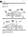
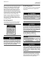
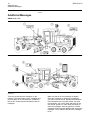
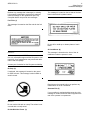
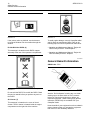
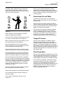
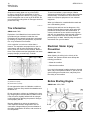
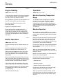
SAFETY
Operation and Maintenance
Manual Excerpt
© 2010 Caterpillar
All Rights Reserved
®
®
SEBU7474-03
February 2007
Operation and
Maintenance
Manual
120H and 135H Motor Graders
1241-Up (Machine)
CBC1-Up (Machine)
CAF1-Up (Machine)
AMX1-Up (Machine)
ALZ1-Up (Machine)
i01658146
Important Safety Information
Most accidents that involve product operation, maintenance and repair are caused by failure to observe
basic safety rules or precautions. An accident can often be avoided by recognizing potentially hazardous
situations before an accident occurs. A person must be alert to potential hazards. This person should also
have the necessary training, skills and tools to perform these functions properly.
Improper operation, lubrication, maintenance or repair of this product can be dangerous and
could result in injury or death.
Do not operate or perform any lubrication, maintenance or repair on this product, until you have
read and understood the operation, lubrication, maintenance and repair information.
Safety precautions and warnings are provided in this manual and on the product. If these hazard warnings
are not heeded, bodily injury or death could occur to you or to other persons.
The hazards are identified by the “Safety Alert Symbol” and followed by a “Signal Word” such as
“DANGER”, “WARNING” or “CAUTION”. The Safety Alert “WARNING” label is shown below.
The meaning of this safety alert symbol is as follows:
Attention! Become Alert! Your Safety is Involved.
The message that appears under the warning explains the hazard and can be either written or pictorially
presented.
Operations that may cause product damage are identified by “NOTICE” labels on the product and in
this publication.
Caterpillar cannot anticipate every possible circumstance that might involve a potential hazard.
The warnings in this publication and on the product are, therefore, not all inclusive. If a tool,
procedure, work method or operating technique that is not specifically recommended by Caterpillar
is used, you must satisfy yourself that it is safe for you and for others. You should also ensure that
the product will not be damaged or be made unsafe by the operation, lubrication, maintenance or
repair procedures that you choose.
The information, specifications, and illustrations in this publication are on the basis of information that
was available at the time that the publication was written. The specifications, torques, pressures,
measurements, adjustments, illustrations, and other items can change at any time. These changes can
affect the service that is given to the product. Obtain the complete and most current information before you
start any job. Caterpillar dealers have the most current information available.
When replacement parts are required for this
product Caterpillar recommends using Caterpillar replacement parts or parts with equivalent
specifications including, but not limited to, physical dimensions, type, strength and material.
Failure to heed this warning can lead to premature failures, product damage, personal injury or
death.
6
Safety Section
Safety Messages
SEBU7474-03
Safety Section
i01892609
Safety Messages
SMCS Code: 7000
Illustration 2
g00985131
Illustration 3
g00985132
There are several specific safety messages on this
machine. The exact location of the messages and
the description of the messages are reviewed in this
section. Please become familiarized with all safety
messages.
SEBU7474-03
7
Safety Section
Safety Messages
Make sure that all of the safety messages are legible.
Clean the safety messages or replace the safety
messages if you cannot read the words. Replace
the illustrations if the illustrations are not legible.
When you clean the safety messages, use a cloth,
water and soap. Do not use solvent, gasoline, or
other harsh chemicals to clean the safety messages.
Solvents, gasoline, or harsh chemicals could loosen
the adhesive that secures the safety message. Loose
adhesive will allow the safety message to fall.
Do Not Operate (2)
This message is placed on the door of the right hand
glove box on machines that are equipped with a
closed ROPS.
Replace any safety message that is damaged, or
missing. If a safety message is attached to a part
that is replaced, install a safety message on the
replacement part. Any Caterpillar dealer can provide
new safety messages.
Do Not Operate (1)
This message is placed on the steering console in
machines that are equipped with an open ROPS.
g00788977
Do not operate or work on this machine unless
you have read and understand the instructions
and warnings in the Operation and Maintenance
Manuals. Failure to follow the instructions or heed
the warnings could result in injury or death. Contact your Caterpillar dealer for replacement manuals. Proper care is your responsibility.
Do Not Weld the ROPS (3)
This message is positioned on the ROPS.
g00920762
Do not operate or work on this machine unless
you have read and understand the instructions
and warnings in the Operation and Maintenance
Manuals. Failure to follow the instructions or heed
the warnings could result in injury or death. Contact your Caterpillar dealer for replacement manuals. Proper care is your responsibility.
g00910837
Structural damage, an overturn, modification, alteration, or improper repair can impair this structure’s protection capability thereby voiding this
certification. Do not weld on or drill holes in the
structure. Consult a Caterpillar dealer to determine this structure’s limitations without voiding
its certification.
This machine has been certified to the standards that
are listed on the certification plate. The maximum
mass of the machine, which includes the operator
and the attachments without a payload, should not
exceed the mass on the certification plate.
8
Safety Section
Safety Messages
SEBU7474-03
No Ether (4)
No Clearance (6)
This message is located on the prescreener assembly
above the hood on some versions of this machine.
This message is positioned at the center pivot on
both sides of the machine.
g00924889
g00802218
If equipped with an air inlet heater (AIH) for cold
weather starting, do not use aerosal types of starting aids such as ether. Such use could result in an
explosion and personal injury.
No clearance for person in this area when machine turns. Severe injury or death from crushing
could occur. Connect steering frame lock between
front and rear frames before lifting, transporting,
or servicing machine in articulation area. Disconnect lock and secure before resuming operation.
Falling Hazard (5)
This message is positioned on the top surface of
each fuel tank.
Accumulator (7)
This message is positioned on the steering
accumulator.
g00974904
g00107646
Do not use the fuel tank as a step or a platform.
The fuel tank surface is not covered with a nonslip
tread. Serious injury or death could occur from a
fall.
High Pressure Cylinder.
Do not remove any parts until pressure has been
relieved to avoid possible personal injury. Charge
with dry nitrogen gas.
SEBU7474-03
9
Safety Section
Safety Messages
Engine Coolant (8)
This message is positioned inside the cover for the
radiator cap.
Improper Connections For Jump
Start Cables (9)
This message is positioned inside the door of the
service center.
g00907918
g00782457
Pressurized System: Hot coolant can cause serious burns. To open the cooling system filler cap,
stop the engine and wait until the cooling system
components are cool. Loosen the cooling system
pressure cap slowly in order to relieve the pressure.
Improper jumper cable connections may cause an
explosion resulting in personal injury. Batteries
may be located in separate compartments. When
using jumper cables, always connect positive (+)
cable to positive (+) terminal of battery connected to starter solenoid and negative (−) cable from
external source to starter negative (−) terminal. (If
not equipped with starter negative terminal, connect to engine block.) Follow procedure in the Operation and Maintenance Manual.
Unplanned Blade Movement (10)
This message is positioned on the cover for the shift
console in the cab.
g00843275
Personal injury could result from sudden movement of the blade when the centershift lockpin is
released. To prevent unexpected blade movement
and possible injury, lower the blade to the ground
before you unlock the centershift linkage. See the
Operation and Maintenance manual for complete
instructions before releasing the centershift lockpin.
10
Safety Section
Additional Messages
SEBU7474-03
i01900238
Additional Messages
SMCS Code: 7000
Illustration 4
g00949330
Illustration 5
g00949327
There are several specific messages on this
machine. The exact location of the messages and
the description of the messages are reviewed in
this section. Please become familiarized with all
messages.
Make sure that all of the messages are legible.
Clean the messages or replace the messages if
you cannot read the words. Replace the illustrations
if the illustrations are not legible. When you clean
the messages, use a cloth, water and soap. Do not
use solvent, gasoline, or other harsh chemicals to
clean the messages. Solvents, gasoline, or harsh
chemicals could loosen the adhesive that secures the
messages. Loose adhesive will allow the messages
to fall.
SEBU7474-03
11
Safety Section
Additional Messages
Replace any message that is damaged, or missing.
If a message is attached to a part that is replaced,
install a message on the replacement part. Any
Caterpillar dealer can provide new messages.
This message is located on the left side of the front
frame behind the lift cylinder bracket.
Fuel Filler (1)
This message is located on the filler tube for the fuel
tanks.
Illustration 8
g00906095
Do not drill or weld top or bottom plates of main
frame.
Air Conditioner (4)
Illustration 6
g00907956
This message is located on the front of the air
conditioner under the operator’s seat.
NOTICE
Use only a Caterpillar approved fast fill system to fuel
machines. Over pressurization may cause tank deformation and fuel spillage.
Contact your Cat dealer for fast fill system availability.
No Step (2)
If equipped, this message is located on the guard
for each fuel tank. This message is also located on
each fuel tank.
Illustration 9
g00939074
Read the service manual before you perform any
maintenance on the air conditioner.
Alternate Exit (5)
If your machine is equipped with a snow wing, this
message is located on the left ROPS support at the
rear of the operator’s compartment.
Illustration 7
g00906093
Do not use the fuel tank as a step. The surface is not
covered with a nonslip tread.
Do Not Weld the Frame. (3)
12
Safety Section
General Hazard Information
Illustration 10
SEBU7474-03
g00907967
Illustration 12
g00949322
If the primary exits are blocked, use the hammer
to break the window. Exit the machine through the
window.
To avoid engine damage, use only Caterpillar radial
seal air filters as replacement filters. Refer to the
following topics for correct replacement instructions:
Do Not Weld the ROPS. (6)
• Operation and Maintenance Manual, “Engine Air
This message is located on each ROPS support
assembly at the rear of the operator’s compartment.
• Operation and Maintenance Manual, “Engine Air
Filter Primary Element - Clean/Replace”
Filter Secondary Element - Replace”
i02443908
General Hazard Information
SMCS Code: 7000
Illustration 11
g00906117
Do not weld the ROPS. Do not drill the ROPS. Read
the service manual before you perform any work on
the ROPS.
Air Cleaner (7)
This message is located on the cover of the air
cleaner. The air cleaner is located inside the engine
compartment on the right side of the machine.
Illustration 13
g00104545
Attach a “Do Not Operate” warning tag or a similar
warning tag to the start switch or to the controls
before you service the equipment or before you
repair the equipment. These warning tags (Special
Instruction, SEHS7332) are available from your
Caterpillar dealer.
Know the width of your equipment in order to maintain
proper clearance when you operate the equipment
near fences or near boundary obstacles.
SEBU7474-03
13
Safety Section
General Hazard Information
Be aware of high voltage power lines and power
cables that are buried. If the machine comes in
contact with these hazards, serious injury or death
may occur from electrocution.
Unless you are instructed otherwise, perform
maintenance with the equipment in the servicing
position. Refer to Operation and Maintenance Manual
for the procedure for placing the equipment in the
servicing position.
Pressurized Air and Water
Pressurized air and/or water can cause debris
and/or hot water to be blown out. This could result in
personal injury.
When pressurized air and/or pressurized water is
used for cleaning, wear protective clothing, protective
shoes, and eye protection. Eye protection includes
goggles or a protective face shield.
Illustration 14
g00702020
Wear a hard hat, protective glasses, and other
protective equipment, as required.
Do not wear loose clothing or jewelry that can snag
on controls or on other parts of the equipment.
Make sure that all protective guards and all covers
are secured in place on the equipment.
Keep the equipment free from foreign material.
Remove debris, oil, tools, and other items from the
deck, from walkways, and from steps.
Secure all loose items such as lunch boxes, tools,
and other items that are not a part of the equipment.
Know the appropriate work site hand signals and
the personnel that are authorized to give the hand
signals. Accept hand signals from one person only.
Do not smoke when you service an air conditioner.
Also, do not smoke if refrigerant gas may be present.
Inhaling the fumes that are released from a flame that
contacts air conditioner refrigerant can cause bodily
harm or death. Inhaling gas from air conditioner
refrigerant through a lighted cigarette can cause
bodily harm or death.
Never put maintenance fluids into glass containers.
Drain all liquids into a suitable container.
Obey all local regulations for the disposal of liquids.
Use all cleaning solutions with care. Report all
necessary repairs.
Do not allow unauthorized personnel on the
equipment.
The maximum air pressure for cleaning purposes
must be reduced to 205 kPa (30 psi) when the
nozzle is deadheaded and the nozzle is used with
an effective chip deflector and personal protective
equipment. The maximum water pressure for
cleaning purposes must be below 275 kPa (40 psi).
Trapped Pressure
Pressure can be trapped in a hydraulic system.
Releasing trapped pressure can cause sudden
machine movement or attachment movement. Use
caution if you disconnect hydraulic lines or fittings.
High pressure oil that is released can cause a hose to
whip. High pressure oil that is released can cause oil
to spray. Fluid penetration can cause serious injury
and possible death.
Fluid Penetration
Pressure can be trapped in the hydraulic circuit long
after the engine has been stopped. The pressure can
cause hydraulic fluid or items such as pipe plugs to
escape rapidly if the pressure is not relieved correctly.
Do not remove any hydraulic components or parts
until pressure has been relieved or personal injury
may occur. Do not disassemble any hydraulic
components or parts until pressure has been relieved
or personal injury may occur. Refer to the Service
Manual for any procedures that are required to
relieve the hydraulic pressure.
14
Safety Section
General Hazard Information
SEBU7474-03
Asbestos Information
Illustration 15
g00687600
Always use a board or cardboard when you check
for a leak. Leaking fluid that is under pressure can
penetrate body tissue. Fluid penetration can cause
serious injury and possible death. A pin hole leak can
cause severe injury. If fluid is injected into your skin,
you must get treatment immediately. Seek treatment
from a doctor that is familiar with this type of injury.
Containing Fluid Spillage
Care must be taken in order to ensure that fluids
are contained during performance of inspection,
maintenance, testing, adjusting and repair of the
equipment. Prepare to collect the fluid with suitable
containers before opening any compartment or
disassembling any component that contains fluids.
Refer to Special Publication, NENG2500, “Caterpillar
Dealer Service Tool Catalog” for the following items:
• Tools that are suitable for collecting fluids and
equipment that is suitable for collecting fluids
•
Illustration 16
g00702022
Caterpillar equipment and replacement parts that are
shipped from Caterpillar are asbestos free. Caterpillar
recommends the use of only genuine Caterpillar
replacement parts. Use the following guidelines
when you handle any replacement parts that contain
asbestos or when you handle asbestos debris.
Use caution. Avoid inhaling dust that might be
generated when you handle components that contain
asbestos fibers. Inhaling this dust can be hazardous
to your health. The components that may contain
asbestos fibers are brake pads, brake bands, lining
material, clutch plates, and some gaskets. The
asbestos that is used in these components is usually
bound in a resin or sealed in some way. Normal
handling is not hazardous unless airborne dust that
contains asbestos is generated.
If dust that may contain asbestos is present, there
are several guidelines that should be followed:
• Never use compressed air for cleaning.
Tools that are suitable for containing fluids and
equipment that is suitable for containing fluids
• Avoid brushing materials that contain asbestos.
Obey all local regulations for the disposal of liquids.
• Avoid grinding materials that contain asbestos.
• Use a wet method in order to clean up asbestos
materials.
• A vacuum cleaner that is equipped with a high
efficiency particulate air filter (HEPA) can also be
used.
• Use exhaust ventilation on permanent machining
jobs.
• Wear an approved respirator if there is no other
way to control the dust.
SEBU7474-03
15
Safety Section
Crushing Prevention and Cutting Prevention
• Comply with applicable rules and regulations
for the work place. In the United States, use
Occupational Safety and Health Administration
(OSHA) requirements. These OSHA requirements
can be found in “29 CFR 1910.1001”.
• Obey environmental regulations for the disposal
of asbestos.
• Stay away from areas that might have asbestos
particles in the air.
Never jump across the starter solenoid terminals
in order to start the engine. Unexpected machine
movement could result.
Whenever there are equipment control linkages the
clearance in the linkage area will change with the
movement of the equipment or the machine. Stay
clear of areas that may have a sudden change in
clearance with machine movement or equipment
movement.
Stay clear of all rotating and moving parts.
Dispose of Waste Properly
If it is necessary to remove guards in order to perform
maintenance, always install the guards after the
maintenance is performed.
Keep objects away from moving fan blades. The fan
blade will throw objects or cut objects.
Do not use a kinked wire cable or a frayed wire cable.
Wear gloves when you handle wire cable.
Illustration 17
g00706404
Improperly disposing of waste can threaten the
environment. Potentially harmful fluids should be
disposed of according to local regulations.
Always use leakproof containers when you drain
fluids. Do not pour waste onto the ground, down a
drain, or into any source of water.
When you strike a retainer pin with force, the retainer
pin can fly out. The loose retainer pin can injure
personnel. Make sure that the area is clear of people
when you strike a retainer pin. To avoid injury to
your eyes, wear protective glasses when you strike
a retainer pin.
Chips or other debris can fly off an object when you
strike the object. Make sure that no one can be
injured by flying debris before striking any object.
i01329099
Burn Prevention
SMCS Code: 7000
i01359664
Crushing Prevention and
Cutting Prevention
SMCS Code: 7000
Support the equipment properly before you perform
any work or maintenance beneath that equipment.
Do not depend on the hydraulic cylinders to hold
up the equipment. Equipment can fall if a control is
moved, or if a hydraulic line breaks.
Do not work beneath the cab of the machine unless
the cab is properly supported.
Unless you are instructed otherwise, never attempt
adjustments while the machine is moving or while
the engine is running.
Do not touch any part of an operating engine.
Allow the engine to cool before any maintenance is
performed on the engine. Relieve all pressure in the
air system, in the oil system, in the lubrication system,
in the fuel system, or in the cooling system before
any lines, fittings or related items are disconnected.
Coolant
When the engine is at operating temperature, the
engine coolant is hot. The coolant is also under
pressure. The radiator and all lines to the heaters or
to the engine contain hot coolant.
Any contact with hot coolant or with steam can cause
severe burns. Allow cooling system components to
cool before the cooling system is drained.
Check the coolant level only after the engine has
been stopped.
16
Safety Section
Fire Prevention and Explosion Prevention
SEBU7474-03
Ensure that the filler cap is cool before removing the
filler cap. The filler cap must be cool enough to touch
with a bare hand. Remove the filler cap slowly in
order to relieve pressure.
Cooling system conditioner contains alkali. Alkali can
cause personal injury. Do not allow alkali to contact
the skin, the eyes, or the mouth.
Oils
Store fuels and lubricants in properly marked
containers away from unauthorized persons. Store
oily rags and any flammable materials in protective
containers. Do not smoke in areas that are used for
storing flammable materials.
Do not operate the machine near any flame.
Hot oil and hot components can cause personal
injury. Do not allow hot oil to contact the skin. Also,
do not allow hot components to contact the skin.
Remove the hydraulic tank filler cap only after the
engine has been stopped. The filler cap must be
cool enough to touch with a bare hand. Follow the
standard procedure in this manual in order to remove
the hydraulic tank filler cap.
Batteries
Electrolyte is an acid. Electrolyte can cause personal
injury. Do not allow electrolyte to contact the skin or
the eyes. Always wear protective glasses for servicing
batteries. Wash hands after touching the batteries
and connectors. Use of gloves is recommended.
i01359795
Fire Prevention and Explosion
Prevention
SMCS Code: 7000
Illustration 18
Remove all flammable materials such as fuel, oil, and
debris from the machine. Do not allow any flammable
materials to accumulate on the machine.
Exhaust shields (if equipped) protect hot exhaust
components from oil spray or fuel spray in case of
a break in a line, in a hose, or in a seal. Exhaust
shields must be installed correctly.
Do not weld on lines or on tanks that contain
flammable fluids. Do not flame cut lines or tanks
that contain flammable fluid. Clean any such lines or
tanks thoroughly with a nonflammable solvent prior
to welding or flame cutting.
Check all electrical wires daily. Repair any wires
that are loose or frayed before you operate the
machine. Clean all electrical connections and tighten
all electrical connections.
Dust that is generated from repairing nonmetallic
hoods or nonmetallic fenders can be flammable
and/or explosive. Repair such components in a well
ventilated area away from open flames or sparks.
Inspect all lines and hoses for wear or for
deterioration. The hoses must be properly routed.
The lines and the hoses must have adequate support
and secure clamps. Tighten all connections to the
recommended torque. Leaks can cause fires.
g00704000
All fuels, most lubricants, and some coolant mixtures
are flammable.
Flammable fluids that are leaking or spilled onto hot
surfaces or onto electrical components can cause
a fire. Fire may cause personal injury and property
damage.
Illustration 19
g00704059
SEBU7474-03
17
Safety Section
Fire Extinguisher Location
Use caution when you are refueling a machine. Do
not smoke while you are refueling a machine. Do
not refuel a machine near open flames or sparks.
Always stop the engine before refueling. Fill the fuel
tank outdoors.
Do not store ether cylinders in living areas or in the
operator compartment of a machine. Do not store
ether cylinders in direct sunlight or in temperatures
above 49 °C (120 °F). Keep ether cylinders away
from open flames or sparks.
Dispose of used ether cylinders properly. Do not
puncture an ether cylinder. Keep ether cylinders
away from unauthorized personnel.
Do not spray ether into an engine if the machine is
equipped with a thermal starting aid for cold weather
starting.
Lines, Tubes and Hoses
Do not bend high pressure lines. Do not strike high
pressure lines. Do not install any lines that are bent
or damaged.
Repair any lines that are loose or damaged. Leaks
can cause fires. Consult your Caterpillar dealer for
repair or for replacement parts.
Illustration 20
g00704135
Gases from a battery can explode. Keep any open
flames or sparks away from the top of a battery. Do
not smoke in battery charging areas.
Check lines, tubes and hoses carefully. Do not use
your bare hand to check for leaks. Use a board or
cardboard to check for leaks. Tighten all connections
to the recommended torque.
Replace the parts if any of the following conditions
are present:
Never check the battery charge by placing a metal
object across the terminal posts. Use a voltmeter or
a hydrometer.
• End fittings are damaged or leaking.
Improper jumper cable connections can cause
an explosion that can result in injury. Refer to
the Operation Section of this manual for specific
instructions.
• Wires are exposed.
Do not charge a frozen battery. This may cause an
explosion.
• Outer coverings are chafed or cut.
• Outer coverings are ballooning.
• Flexible part of the hoses are kinked.
• Outer covers have embedded armoring.
Fire Extinguisher
• End fittings are displaced.
Make sure that a fire extinguisher is available. Be
familiar with the operation of the fire extinguisher.
Inspect the fire extinguisher and service the fire
extinguisher regularly. Obey the recommendations
on the instruction plate.
Make sure that all clamps, guards, and heat shields
are installed correctly. During machine operation, this
will help to prevent vibration, rubbing against other
parts, and excessive heat.
Ether
Ether is flammable and poisonous.
Use ether in well ventilated areas. Do not smoke
while you are replacing an ether cylinder or while you
are using an ether spray.
i01258143
Fire Extinguisher Location
SMCS Code: 7000
Do not weld a bracket on the Rollover Protective
Structure (ROPS) in order to install the fire
extinguisher. Also, do not drill holes in the ROPS in
order to mount the fire extinguisher on the ROPS.
18
Safety Section
Tire Information
SEBU7474-03
Strap the mounting plate to a leg of the ROPS
in order to mount the fire extinguisher. If the fire
extinguisher weighs more than 4.5 kg (10 lb), mount
the fire extinguisher low on one leg of the ROPS. Do
not mount the fire extinguisher on the upper one-third
portion of the leg.
i01557411
Tire Information
SMCS Code: 7000
Explosions of air inflated tires have resulted from
heat-induced gas combustion inside the tires.
Explosions can be caused by heat that is generated
by welding, by heating rim components, by external
fire, or by excessive use of brakes.
A tire explosion is much more violent than a
blowout. The explosion can propel the tire, the rim
components, and the axle components as far as
500 m (1500 ft) or more from the machine. Both the
force of the explosion and the flying debris can cause
property damage, personal injury, or death.
To avoid overinflation, proper nitrogen inflation
equipment and training in the usage of the equipment
are necessary. A tire blowout or a rim failure can
result from improper equipment or from misused
equipment.
When you inflate a tire, stand behind the tread and
use a self-attaching chuck.
Servicing tires and rims can be dangerous. Only
trained personnel that use proper tools and proper
procedures should perform this maintenance. If
correct procedures are not used for servicing tires
and rims, the assemblies could burst with explosive
force. This explosive force can cause serious
personal injury or death. Carefully obey the specific
instructions from your tire dealer.
i01122596
Electrical Storm Injury
Prevention
SMCS Code: 7000
When lightning is striking in the vicinity of the
machine, the operator should never attempt the
following procedures:
• Mount the machine.
• Dismount the machine.
If you are in the operator’s station during an electrical
storm, stay in the operator’s station. If you are on the
ground during an electrical storm, stay away from
the vicinity of the machine.
Illustration 21
g00337832
(A) At least 15 m (50 ft)
(B) At least 500 m (1500 ft)
Do not approach a warm tire. Maintain a minimum
distance, as shown. Stay outside the shaded area in
Illustration 21.
i01861206
Before Starting Engine
SMCS Code: 1000; 7000
Do not use water or calcium as a ballast for the tires.
Dry nitrogen gas is recommended for inflation of tires.
If the tires were originally inflated with air, nitrogen
is still preferred for adjusting the pressure. Nitrogen
mixes properly with air.
Nitrogen inflated tires reduce the potential of
a tire explosion because nitrogen does not aid
combustion. Nitrogen helps to prevent oxidation of
the rubber, deterioration of rubber, and corrosion of
rim components.
Illustration 22
g00949005
SEBU7474-03
19
Safety Section
Before Starting Engine
Place frame lock link (1) in the storage bracket. The
frame lock link must be removed from the locked
position in order to articulate the machine.
Illustration 23
g00949012
Remove wheel lean bolt (2) from the locked position.
The wheel lean bolt must be removed in order to lean
the wheels.
Start the engine only from the operator’s
compartment. Never short across the starter
terminals or across the batteries. Shorting could
bypass the engine neutral start system. Shorting
could also damage the electrical system.
Illustration 25
g00810739
The mirrors on your machine may be different. Adjust
the mirrors for the best operator vision. Adjust the
inside mirror or the inside mirrors before you operate
the machine. If the machine is equipped with outside
mirrors, adjust the outside mirrors before you operate
the machine.
Inspect the condition of the seat belt and the condition
of mounting hardware. Replace any damaged parts
and any worn parts. Regardless of appearance,
replace the seat belt after three years of use. Do not
use a seat belt extension on a retractable seat belt.
Adjust the seat in order to achieve full pedal travel
when the operator’s back is against the back of the
seat. Adjust the steering column tilt lever in order
to enhance the operation of the machine from the
operator’s seat. Adjust the steering wheel tilt lock in
order to enhance the operation of the machine from
the operator’s seat.
Illustration 24
g00811951
Make sure that the machine horn works properly.
Make sure that the machine is equipped with a
lighting system that is adequate for the job conditions.
Make sure that all lights are working properly.
Before you start the engine or before you move the
machine, make sure that no one is on the machine,
underneath the machine, or around the machine.
Make sure that there are no personnel in the area.
20
Safety Section
Engine Starting
SEBU7474-03
i02441047
i01863695
Engine Starting
Operation
SMCS Code: 1000; 7000
SMCS Code: 7000; 7600
If a warning tag is attached to the engine start switch
or to the machine controls, do not start the engine.
Also, do not move any machine controls.
Machine Operating Temperature
Range
Move all hydraulic controls to the HOLD position or to
the OFF position before you start the engine.
The standard machine configuration is intended
for use within an ambient temperature range
of −40 °C (−40 °F) to 50 °C (122 °F). Special
configurations for different ambient temperatures
may be available. Consult your Caterpillar dealer for
additional information on special configurations of
your machine.
Move the transmission control (lever) to the
NEUTRAL position.
Engage the parking brake control.
Diesel engine exhaust contains products of
combustion which can be harmful to your health.
Always start the engine in a well ventilated area.
Always operate the engine in a well ventilated area.
If you are in an enclosed area, vent the exhaust to
the outside.
i01901299
Before Operation
SMCS Code: 7000; 7600
Clear all personnel from the machine and from the
area.
Clear all obstacles from the path of the machine.
Beware of hazards such as wires, ditches, etc.
Make sure that all windows are clean. Secure the
doors in the open position or in the shut position.
Secure the windows in the open position or in the
shut position.
Machine Operation
Only operate the machine while you are in a seat.
The seat belt must be fastened while you operate the
machine. Only operate the controls while the engine
is running.
Before you operate the machine, remove the wheel
lean locking bolt from the wheel lean lock bracket.
Make sure that the frame lock pin is stored in the
unlocked position. The steering frame lock link must
be removed in order to steer the machine.
Do not use the wheel lean locking bolt and the wheel
lean lock bracket in order to center the wheel lean
of the machine.
While you operate the machine slowly in an open
area, check for proper operation of all controls and all
protective devices.
Before you move the machine, you must make sure
that no one will be endangered.
Remove the wheel lean locking bolt from the wheel
lean lock bracket. Make sure that the frame lock pin
is stored in the unlocked position. The frame lock pin
must be removed in order to steer the machine.
Do not allow riders on the machine unless the
machine has the following equipment:
For the best vision of the area that is close to the
machine, adjust the rear view mirrors (if equipped).
• additional seat belt
Make sure that the machine horn, the backup alarm
(if equipped) and all other warning devices are
working properly.
Fasten the seat belt securely.
• additional seat
• Rollover Protective Structure (ROPS)
Reduce engine speed when you maneuver in tight
quarters or when you are going over a hill.
When you operate the machine downhill, use two
transmission gears less than the transmission gear
that is used when you operate the machine up the
same hill.
SEBU7474-03
21
Safety Section
Engine Stopping
Do not allow the engine to overspeed when you
operate the machine downhill. If overspeed exists,
use the service brake control to decrease the speed
to a level that will allow you to downshift. Repeat this
process until a stable speed is obtained.
i01681008
Parking
SMCS Code: 7000
Note any needed repairs during machine operation.
Report any needed repairs.
Park the machine on a level surface. If you must park
on a grade, chock the machine’s wheels.
Carry attachments approximately 40 cm (15 inches)
above ground level. Do not go close to the edge of a
cliff, an excavation, or an overhang.
Apply the service brake in order to stop the
machine. Move the transmission control (lever) to
the NEUTRAL position. Move the throttle control to
the LOW IDLE position.
If the machine begins to sideslip downward on a
grade, immediately remove the load and turn the
machine downhill.
Engage the parking brake.
Avoid any conditions that can lead to tipping the
machine. The machine can tip when you work on
hills, on banks and on slopes. Also, the machine
can tip when you cross ditches, ridges or other
unexpected obstructions.
Stop the engine.
Avoid operating the machine across the slope. When
possible, operate the machine up the slopes and
down the slopes.
Maintain control of the machine. Do not overload the
machine beyond the machine capacity.
Never straddle a wire cable. Never allow other
personnel to straddle a wire cable.
Before you maneuver the machine, make sure
that no personnel are between the machine and
attachments.
Know the maximum dimensions of your machine.
Always keep the Rollover Protective Structure
(ROPS) installed during machine operation.
i02624835
Engine Stopping
SMCS Code: 1000; 7000
Do not stop the engine immediately after the
machine has been operated under load. This can
cause overheating and accelerated wear of engine
components.
After the machine is parked and the parking brake
is engaged, allow the engine to run for two minutes
before shutdown. This allows hot areas of the engine
to cool gradually.
Lower all equipment to the ground. Activate any
control locks.
Turn the engine start switch to the OFF position and
remove the engine start switch key.
Turn the battery disconnect switch to the OFF
position. Remove the disconnect switch key if you
do not operate the machine for an extended period
of time. This will prevent drainage of the battery. A
battery short circuit, any current draw from certain
components, and vandalism can cause drainage of
the battery.
i01329161
Equipment Lowering with
Engine Stopped
SMCS Code: 7000
Before lowering any equipment with the engine
stopped, clear the area around the equipment of
all personnel. The procedure to use will vary with
the type of equipment to be lowered. Keep in mind
most systems use a high pressure fluid or air to
raise or lower equipment. The procedure will cause
high pressure air, hydraulic, or some other media
to be released in order to lower the equipment.
Wear appropriate personal protective equipment and
follow the established procedure in the Operation
and Maintenance Manual, “Equipment Lowering with
Engine Stopped” in the Operation Section of the
manual.
22
Safety Section
Sound Information and Vibration Information
SEBU7474-03
i02703472
Sound Information and
Vibration Information
SMCS Code: 7000
Sound Level Information
The operator Equivalent Sound Pressure Level
(Leq) is 77 dB(A) when “ANSI/SAE J1166 OCT 98”
is used to measure the value for an enclosed cab.
This is a work cycle sound exposure level. The cab
was properly installed and maintained. The test was
conducted with the cab doors and the cab windows
closed.
Hearing protection may be needed when the
machine is operated with an open operator station for
extended periods or in a noisy environment. Hearing
protection may be needed when the machine is
operated with a cab that is not properly maintained or
when the doors and windows are open for extended
periods or in a noisy environment.
The average exterior sound pressure level is 71
dB(A) when the “SAE J88Apr95 - Constant Speed
Moving Test” procedure is used to measure the value
for the standard machine. The measurement was
conducted under the following conditions: distance of
15 m (49.2 ft) and “the machine moving forward in an
intermediate gear ratio”.
Sound Level Information for
Machines in European Union
Countries and in Countries that
Adopt the “EU Directives”
The dynamic operator sound pressure level is 76
dB(A) when “ISO 6396:1992” is used to measure the
value for an enclosed cab. The cab was properly
installed and maintained. The test was conducted
with the cab doors and the cab windows closed.
“The European Union Physical
Agents (Vibration) Directive
2002/44/EC”
Vibration Data for Motor Graders
Information Concerning Hand/Arm Vibration
Level
When the machine is operated according to the
intended use, the hand/arm vibration of this machine
is below 2.5 meter per second squared.
Information Concerning Whole Body Vibration
Level
This section provides vibration data and a method for
estimating the vibration level for motor graders.
Note: Vibration levels are influenced by many
different parameters. Many items are listed below.
• Operator training, behavior, mode, and stress
• Job site organization, preparation, environment,
weather, and material
• Machine type, quality of the seat, quality of the
suspension system, attachments, and condition of
the equipment
It is not possible to get precise vibration levels for
this machine. The expected vibration levels can be
estimated with the information in Table 1 in order
to calculate the daily vibration exposure. A simple
evaluation of the machine application can be used.
Estimate the vibration levels for the three vibration
directions. For typical operating conditions, use the
average vibration levels as the estimated level. With
an experienced operator and smooth terrain, subtract
the Scenario Factors from the average vibration level
in order to obtain the estimated vibration level. For
aggressive operations and severe terrain, add the
Scenario Factors to the average vibration level in
order to obtain the estimated vibration level.
Note: All vibration levels are in meter per second
squared.
SEBU7474-03
23
Safety Section
Sound Information and Vibration Information
Table 1
“ISO Reference Table A - Equivalent vibration levels of whole body vibration emission for earthmoving equipment.”
Machine
Type
Vibration Levels
Scenario Factors
Typical Operating
Activity
X axis
Y axis
Z axis
X axis
Y axis
Z axis
finish grading
0,41
0,48
0,38
0,22
0,26
0,14
hard grading
0,61
0,64
0,78
0,21
0,21
0,30
transfer
0,39
0,36
0,58
0,25
0,25
0,34
Motor
Graders
Note: Refer to “ISO/TR 25398 Mechanical Vibration Guideline for the assessment of exposure to whole
body vibration of ride on operated earthmoving
machines” for more information about vibration.
This publication uses data that is measured
by international institutes, organizations and
manufacturers. This document provides information
about the whole body exposure of operators of
earthmoving equipment. Refer to Operation and
Maintenance Manual, SEBU8257, “The European
Union Physical Agents (Vibration) Directive
2002/44/EC” for more information about machine
vibration levels.
The Caterpillar suspension seat meets the criteria of
“ISO 7096”. This represents vertical vibration level
under severe operating conditions. This seat is tested
with the input “spectral class EM4”. The seat has a
transmissibility factor of “SEAT<1.1”.
The whole body vibration level of the machine varies.
There is a range of values. The low value is 0.5
meter per second squared. The machine meets the
short term level for the design of the seat in “ISO
7096”. The value is 0.63 meter per second squared
for this machine.
Guidelines for Reducing Vibration Levels on
Earthmoving Equipment
Properly adjust machines. Properly maintain
machines. Operate machines smoothly. Maintain the
conditions of the terrain. The following guidelines can
help reduce the whole body vibration level:
1. Use the right type and size of machine, equipment,
and attachments.
2. Maintain machines according to the
manufacturer’s recommendations.
a. Tire pressures
b. Fill any ditches and holes.
c. Provide machines and schedule time in order
to maintain the conditions of the terrain.
4. Use a seat that meets “ISO 7096”. Keep the seat
maintained and adjusted.
a. Adjust the seat and suspension for the weight
and the size of the operator.
b. Inspect and maintain the seat suspension and
adjustment mechanisms.
5. Perform the following operations smoothly.
a. Steer
b. Brake
c. Accelerate.
d. Shift the gears.
6. Move the attachments smoothly.
7. Adjust the machine speed and the route in order
to minimize the vibration level.
a. Drive around obstacles and rough terrain.
b. Slow down when it is necessary to go over
rough terrain.
8. Minimize vibrations for a long work cycle or a long
travel distance.
a. Use machines that are equipped with
suspension systems.
b. Use the ride control system on motor graders.
b. Brake and steering systems
c. If no ride control system is available, reduce
speed in order to prevent bounce.
c. Controls, hydraulic system and linkages
d. Haul the machines between workplaces.
3. Keep the terrain in good condition.
a. Remove any large rocks or obstacles.
9. Less operator comfort may be caused by other risk
factors. The following guidelines can be effective
in order to provide better operator comfort:
24
Safety Section
Operator Station
a. Adjust the seat and adjust the controls in order
to achieve good posture.
b. Adjust the mirrors in order to minimize twisted
posture.
c. Provide breaks in order to reduce long periods
of sitting.
d. Avoid jumping from the cab.
e. Minimize repeated handling of loads and lifting
of loads.
f. Minimize any shocks and impacts during sports
and leisure activities.
Sources
The vibration information and calculation procedure
is based on “ISO/TR 25398 Mechanical Vibration
- Guideline for the assessment of exposure
to whole body vibration of ride on operated
earthmoving machines”. Harmonized data is
measured by international institutes, organizations
and manufacturers.
This literature provides information about assessing
the whole body vibration exposure of operators of
earthmoving equipment. The method is based on
measured vibration emission under real working
conditions for all machines.
You should check the original directive. This
document summarizes part of the content of the
applicable law. This document is not meant to
substitute the original sources. Other parts of these
documents are based on information from the United
Kingdom Health and Safety Executive.
Refer to Operation and Maintenance Manual,
SEBU8257, “The European Union Physical
Agents (Vibration) Directive 2002/44/EC” for more
information about vibration.
Consult your local Caterpillar dealer for more
information about machine features that minimize
vibration levels. Consult your local Caterpillar dealer
about safe machine operation.
Use the following web site in order to find your local
dealer:
Caterpillar, Inc.
www.cat.com
SEBU7474-03
i01649970
Operator Station
SMCS Code: 7000
Any modifications to the inside of the operator
station should not project into the operator space.
The addition of a radio, fire extinguisher, and other
equipment must be installed so that the defined
operator space is maintained. Any item that is brought
into the cab should not project into the defined
operator space. A lunch box or other loose items
must be secured. Objects must not pose an impact
hazard in rough terrain or in the event of a rollover.
i01992325
Guards
(Operator Protection)
SMCS Code: 7000
There are different types of guards that are used to
protect the operator. The machine and the machine
application determines the type of guard that should
be used.
A daily inspection of the guards is required in order to
check for structures that are bent, cracked or loose.
Never operate a machine with a damaged structure.
The operator becomes exposed to a hazardous
situation if the machine is used improperly or if poor
operating techniques are used. This situation can
occur even though a machine is equipped with an
appropriate protective guard. Follow the established
operating procedures that are recommended for your
machine.
SEBU7474-03
25
Safety Section
Guards
Rollover Protective Structure
(ROPS), Falling Object Protective
Structure (FOPS) or Tip Over
Protection Structure (TOPS)
• Demolition applications
The ROPS/FOPS Structure (if equipped) on your
machine is specifically designed, tested and certified
for that machine. Excavators are not equipped
with ROPS structures. Any alteration or any
modification to the ROPS/FOPS Structure could
weaken the structure. This places the operator
into an unprotected environment. Modifications or
attachments that cause the machine to exceed the
weight that is stamped on the certification plate also
place the operator into an unprotected environment.
Excessive weight may inhibit the brake performance,
the steering performance and the ROPS. The
protection that is offered by the ROPS/FOPS
Structure will be impaired if the ROPS/FOPS
Structure has structural damage. Damage to the
structure can be caused by an overturn, a falling
object, a collision, etc.
Additional guards may be required for specific
applications or work tools. The Operation and
Maintenance Manual for your machine or your
work tool will provide specific requirements for the
guards. Consult your Caterpillar dealer for additional
information.
Do not mount items (fire extinguishers, first aid
kits, work lights, etc) by welding brackets to the
ROPS/FOPS Structure or by drilling holes in the
ROPS/FOPS Structure. Welding brackets or drilling
holes in the ROPS/FOPS Structures can weaken
the structures. Consult your Caterpillar dealer for
mounting guidelines.
The Tip Over Protection Structure (TOPS) is
another type of guard that is used on mini hydraulic
excavators. This structure protects the operator in
the event of a tipover. The same guidelines for the
inspection, the maintenance and the modification of
the ROPS/FOPS Structure are required for the Tip
Over Protection Structure.
Other Guards (If Equipped)
Protection from flying objects and/or falling objects is
required for special applications. Logging applications
and demolition applications are two examples that
require special protection.
A front guard needs to be installed when a work
tool that creates flying objects is used. Mesh
front guards that are approved by Caterpillar or
polycarbonate front guards that are approved by
Caterpillar are available for machines with a cab or
an open canopy. On machines that are equipped with
cabs, the windshield should also be closed. Safety
glasses are recommended when flying hazards exist
for machines with cabs and machines with open
canopies.
If the work material extends above the cab, top
guards and front guards should be used. Typical
examples of this type of application are listed below:
• Rock quarries
• Forestry products