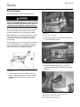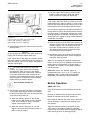
1
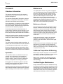
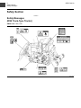
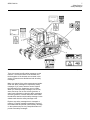
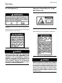
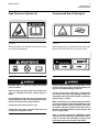
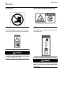
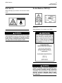
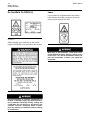
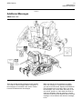
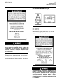
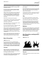
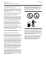
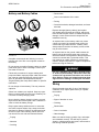
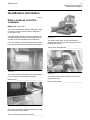
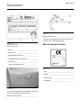
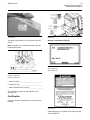
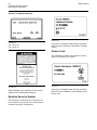
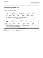
SAFETY
Operation and Maintenance
Manual Excerpt
© 2010 Caterpillar
All Rights Reserved
®
®
SEBU7418-08
November 2010
Operation and
Maintenance
Manual
D5N Track-Type Tractor
AKD1-Up (Machine)
AGG1-Up (Machine)
CFH1-Up (Machine)
CKT1-Up (Machine)
SAFETY.CAT.COM
i03991620
Important Safety Information
Most accidents that involve product operation, maintenance and repair are caused by failure to observe
basic safety rules or precautions. An accident can often be avoided by recognizing potentially hazardous
situations before an accident occurs. A person must be alert to potential hazards. This person should also
have the necessary training, skills and tools to perform these functions properly.
Improper operation, lubrication, maintenance or repair of this product can be dangerous and
could result in injury or death.
Do not operate or perform any lubrication, maintenance or repair on this product, until you have
read and understood the operation, lubrication, maintenance and repair information.
Safety precautions and warnings are provided in this manual and on the product. If these hazard warnings
are not heeded, bodily injury or death could occur to you or to other persons.
The hazards are identified by the “Safety Alert Symbol” and followed by a “Signal Word” such as
“DANGER”, “WARNING” or “CAUTION”. The Safety Alert “WARNING” label is shown below.
The meaning of this safety alert symbol is as follows:
Attention! Become Alert! Your Safety is Involved.
The message that appears under the warning explains the hazard and can be either written or pictorially
presented.
A non-exhaustive list of operations that may cause product damage are identified by “NOTICE” labels
on the product and in this publication.
Caterpillar cannot anticipate every possible circumstance that might involve a potential hazard.
The warnings in this publication and on the product are, therefore, not all inclusive. You must
not use this product in any manner different from that considered by this manual without first
satisfying yourself that you have considered all safety rules and precautions applicable to the
operation of the product in the location of use, including site-specific rules and precautions
applicable to the worksite. If a tool, procedure, work method or operating technique that is not
specifically recommended by Caterpillar is used, you must satisfy yourself that it is safe for you
and for others. You should also ensure that the product will not be damaged or become unsafe by
the operation, lubrication, maintenance or repair procedures that you intend to use.
The information, specifications, and illustrations in this publication are on the basis of information that
was available at the time that the publication was written. The specifications, torques, pressures,
measurements, adjustments, illustrations, and other items can change at any time. These changes can
affect the service that is given to the product. Obtain the complete and most current information before you
start any job. Cat dealers have the most current information available.
When replacement parts are required for this
product Caterpillar recommends using Cat replacement parts or parts with equivalent specifications including, but not limited to, physical
dimensions, type, strength and material.
Failure to heed this warning can lead to premature failures, product damage, personal injury or
death.
In the United States, the maintenance, replacement, or repair of the emission control devices and
systems may be performed by any repair establishment or individual of the owner's choosing.
4
Foreword
SEBU7418-08
Foreword
Maintenance
Literature Information
The maintenance section is a guide to equipment
care. The Maintenance Interval Schedule (MIS) lists
the items to be maintained at a specific service
interval. Items without specific intervals are listed
under the "When Required" service interval. The
Maintenance Interval Schedule lists the page
number for the step-by-step instructions required to
accomplish the scheduled maintenance. Use the
Maintenance Interval Schedule as an index or "one
safe source" for all maintenance procedures.
This manual should be stored in the operator's
compartment in the literature holder or seat back
literature storage area.
This manual contains safety information, operation
instructions, transportation information, lubrication
information and maintenance information.
Some photographs or illustrations in this publication
show details or attachments that can be different
from your machine. Guards and covers might have
been removed for illustrative purposes.
Continuing improvement and advancement of
product design might have caused changes to your
machine which are not included in this publication.
Read, study and keep this manual with the machine.
Whenever a question arises regarding your machine,
or this publication, please consult your Caterpillar
dealer for the latest available information.
Safety
The safety section lists basic safety precautions. In
addition, this section identifies the text and locations
of warning signs and labels used on the machine.
Read and understand the basic precautions listed
in the safety section before operating or performing
lubrication, maintenance and repair on this machine.
Operation
The operation section is a reference for the new
operator and a refresher for the experienced
operator. This section includes a discussion of
gauges, switches, machine controls, attachment
controls, transportation and towing information.
Photographs and illustrations guide the operator
through correct procedures of checking, starting,
operating and stopping the machine.
Operating techniques outlined in this publication are
basic. Skill and techniques develop as the operator
gains knowledge of the machine and its capabilities.
Maintenance Intervals
Use the service hour meter to determine servicing
intervals. Calendar intervals shown (daily, weekly,
monthly, etc.) can be used instead of service hour
meter intervals if they provide more convenient
servicing schedules and approximate the indicated
service hour meter reading. Recommended service
should always be performed at the interval that
occurs first.
Under extremely severe, dusty or wet operating
conditions, more frequent lubrication than is
specified in the maintenance intervals chart might
be necessary.
Perform service on items at multiples of the original
requirement. For example, at every 500 service
hours or 3 months, also service those items listed
under every 250 service hours or monthly and every
10 service hours or daily.
California Proposition 65 Warning
Diesel engine exhaust and some of its constituents
are known to the State of California to cause cancer,
birth defects, and other reproductive harm.
Battery posts, terminals and related accessories
contain lead and lead compounds. Wash hands
after handling.
Certified Engine Maintenance
Proper maintenance and repair is essential to keep
the engine and machine systems operating correctly.
As the heavy duty off-road diesel engine owner, you
are responsible for the performance of the required
maintenance listed in the Owner Manual, Operation
and Maintenance Manual, and Service Manual.
SEBU7418-08
5
Foreword
It is prohibited for any person engaged in the
business of repairing, servicing, selling, leasing, or
trading engines or machines to remove, alter, or
render inoperative any emission related device or
element of design installed on or in an engine or
machine that is in compliance with the regulations
(40 CFR Part 89). Certain elements of the machine
and engine such as the exhaust system, fuel system,
electrical system, intake air system and cooling
system may be emission related and should not be
altered unless approved by Caterpillar.
Machine Capacity
Additional attachments or modifications may exceed
machine design capacity which can adversely affect
performance characteristics. Included would be
stability and system certifications such as brakes,
steering, and rollover protective structures (ROPS).
Contact your Caterpillar dealer for further information.
Caterpillar Product Identification
Number
Effective First Quarter 2001 the Caterpillar Product
Identification Number (PIN) has changed from 8 to 17
characters. In an effort to provide uniform equipment
identification, Caterpillar and other construction
equipment manufacturers are moving to comply
with the latest version of the product identification
numbering standard. Non-road machine PINs are
defined by ISO 10261. The new PIN format will apply
to all Caterpillar machines and generator sets. The
PIN plates and frame marking will display the 17
character PIN. The new format will look like the
following:
Illustration 1
g00751314
Where:
1. Caterpillar's World Manufacturing Code (characters
1-3)
2. Machine Descriptor (characters 4-8)
3. Check Character (character 9)
4. Machine Indicator Section (MIS) or Product
Sequence Number (characters 10-17). These were
previously referred to as the Serial Number.
Machines and generator sets produced before First
Quarter 2001 will maintain their 8 character PIN
format.
Components such as engines, transmissions, axles,
etc. and work tools will continue to use an 8 character
Serial Number (S/N).
6
Safety Section
Safety Messages
SEBU7418-08
Safety Section
i02424681
Safety Messages
(D5N Track-Type Tractor)
SMCS Code: 7000; 7405
Illustration 2
g01211654
SEBU7418-08
Illustration 3
There are several specific safety messages on this
machine. The exact location of the hazards and
the description of the hazards are reviewed in this
section. Please become familiarized with all safety
messages.
Make sure that all of the safety messages are legible.
Clean the safety messages or replace the safety
messages if you cannot read the words. Replace
the illustrations if the illustrations are not visible.
When you clean the safety messages, use a cloth,
water, and soap. Do not use solvent, gasoline, or
other harsh chemicals to clean the safety messages.
Solvents, gasoline, or harsh chemicals could loosen
the adhesive that secures the safety message. Loose
adhesive will allow the safety message to fall.
Replace any safety message that is damaged or
missing. If a safety message is attached to a part of
the machine that is replaced, install a safety message
on the replacement part. Any Caterpillar dealer can
provide new safety messages.
7
Safety Section
Safety Messages
g01211659
8
Safety Section
Safety Messages
SEBU7418-08
Do Not Operate (1)
Illustration 4
Improper Connections for Jump
Start Cables (2)
g00930652
Safety Message (1) is positioned 230 mm (9.05 inch)
above the bottom of the left post.
Illustration 5
g01211667
Safety Message (2) is in the battery compartment.
g01211662
DO NOT OPERATE OR WORK ON THIS MACHINE
UNLESS YOU HAVE READ AND UNDERSTAND
THE INSTRUCTIONS AND WARNINGS IN THE
OPERATION AND MAINTENANCE MANUALS.
FAILURE TO FOLLOW THE INSTRUCTIONS OR
HEED THE WARNINGS COULD RESULT IN INJURY OR DEATH. CONTACT ANY CATERPILLAR
DEALER FOR REPLACEMENT MANUALS. PROPER CARE IS YOUR RESPONSIBILITY.
g01211675
Improper jumper cable connections can cause an
explosion resulting in personal injury. Batteries
can be located in separate compartments. When
using jumper cable always connect positive (+) cable to positive (+) terminal of battery connected to
starter solenoid and negative (−) cable from external source to starter negative (−) terminal. (If not
equipped with starter negative terminal, connect
to engine block.)
SEBU7418-08
9
Safety Section
Safety Messages
High Pressure Cylinder (3)
Illustration 6
Compressed Recoil Spring (4)
g01211678
Safety Message (3) is attached to the cover for each
recoil spring compartment.
Illustration 7
g01056162
Safety Message (4) is located inside both track roller
frames at the end of the tube for the roller frame.
g01211683
g01211685
Personal injury or death can result from grease
under pressure.
Personal injury or death can result from a compressed recoil spring being released suddenly using incorrect disassembly procedures.
Grease coming out of the relief valve under pressure can penetrate the body causing injury or
death.
Do not watch the relief valve to see if grease is escaping. Watch the track or track adjustment cylinder to see if the track is being loosened.
Loosen the relief valve one turn only.
If track does not loosen, close the relief valve and
contact your Caterpillar dealer.
A recoil spring that is still held in compression
can result in the recoil spring being released unexpectedly with extreme force which could cause
serious injury or death.
Make sure that the correct disassembly procedure
is used, if a front track roller frame that has a crack
in the parent metal or weld connection (or a tubular section that has separated from the front of
the frame assembly) when the recoil spring is still
held in compression.
Refer to Special Instruction, SMHS8273 which
contains the disassembly procedure that must be
used to decrease the possibility of injury while
performing service on the track roller frame.
10
Safety Section
Safety Messages
SEBU7418-08
No Step (5)
Illustration 8
Hot Coolant Under Pressure (6)
g00936182
This safety message is located on both the blade
angle cylinders. This area may be oily and slippery.
Illustration 9
g01211688
Safety Message (5) is located under the access door
to the radiator cap.
g01211686
Falling Hazard - Area may be oily and slippery. Do
not step on angle blade cylinders. Serious injury
or death could occur from a fall.
g00782457
Pressurized system: Hot coolant can cause serious burn. To open cap, stop engine, wait until radiator is cool. Then loosen cap slowly to relieve
the pressure.
SEBU7418-08
11
Safety Section
Safety Messages
Seat belt (7)
Do Not Weld on FOPS (8)
Safety Message (6) is located on the left side of dash
panel.
Illustration 10
g01211690
g01211691
Safety Message (7) is located on the FOPS.
A seat belt should be worn at all times during machine operation to prevent serious injury or death
in the event of an accident or machine overturn.
Failure to wear a seat belt during machine operation may result in serious injury or death.
g01211693
Structural damage, an overturn, modification, alteration, or improper repair can impair this structure's protection capability thereby voiding this
certification. Do not weld on or drill holes in the
structure. Consult a Caterpillar dealer to determine this structure's limitations without voiding
its certification.
12
Safety Section
Safety Messages
SEBU7418-08
Laser
Do Not Weld On ROPS (9)
If your machine is equipped with the AccuGrade Laser System, this safety message is located on
each leg of the tripod for the laser.
Illustration 11
g01211695
Safety Message (8) is positioned on the vertical
support of the ROPS on the right side of the machine.
g01211700
Movement of the transmitter could cause unexpected blade movement. Death or serious injury
could occur. Turn off the transmitter before you
move the transmitter or before you adjust the
transmitter.
g01211698
Structural damage, an overturn, modification, alteration, or improper repair, can impair this structure's protective capability thereby voiding this
certification. Do not weld on or drill holes in the
structure. Consult a Caterpillar dealer to determine this structure's limitations without voiding
its certification.
SEBU7418-08
13
Safety Section
Additional Messages
i02424775
Additional Messages
SMCS Code: 7405
Illustration 12
There are several specific messages on this machine.
The location of the messages and the description of
the messages are reviewed in this section. Please
become familiarized with all messages.
g01211803
Make sure that all of the messages are legible.
Clean the messages or replace the messages if
you cannot read the words. Replace the illustrations
if the illustrations are not legible. When you clean
the messages, use a cloth, water and soap. Do not
use solvent, gasoline, or other harsh chemicals to
clean the messages. Solvents, gasoline, or harsh
chemicals could loosen the adhesive that secures the
messages. Loose adhesive will allow the messages
to fall.
14
Safety Section
Additional Messages
SEBU7418-08
Replace any message that is damaged, or missing.
If a message is attached to a part that is replaced,
install a message on the replacement part. Any
Caterpillar dealer can provide new messages.
Air Conditioner (1)
When an air conditioner is present, this message
identifies the serpentine belt as the drive belt for the
air conditioner compressor also.
• The serpentine belt can be inspected for looseness
and fraying.
This safety message is located on the left side of the
instrument panel.
• The serpentine belt is self-adjusting.
Reference: See Operation and Maintenance Manual,
“Maintenance Interval Schedule” for all maintenance
recommendations.
Do Not Weld on FOPS (3)
Illustration 13
g01211806
This safety message for the air conditioner has the
appropriate information for the following services: the
air conditioner lubricant, the refrigerant charge, and
the refrigerant capacity.
Illustration 15
Read the service manual before you perform any
service to the air conditioner.
(S/N: AGG903-Up)
Belt Mounting (2)
Safety Message (4) is located on the FOPS.
This safety message is located inside the right engine
compartment on the upper flange of the alternator
guard.
Illustration 14
g01211808
(S/N: AKD802-Up)
g01211813
SEBU7418-08
15
Safety Section
Additional Messages
Do Not Weld on ROPS (4)
Illustration 16
g01211818
(S/N: AGG903-Up)
(S/N: AKD802-Up)
Safety Message (5) is positioned on the vertical
support of the ROPS on the right side of the machine.
g01211814
Structural damage, an overturn, modification, alteration, or improper repair can impair this structure's protection capability thereby voiding this
certification. Do not weld on or drill holes in the
structure. Consult a Caterpillar dealer to determine this structure's limitations without voiding
its certification.
This machine has been certified to the standards that
are listed on the certification plate. The maximum
mass of the machine, which includes the operator
and the attachments without a payload, should not
exceed the mass on the certification label.
g01211821
Structural damage, an overturn, modification, alteration, or improper repair, can impair this structure's protective capability thereby voiding this
certification. Do not weld on or drill holes in the
structure. Consult a Caterpillar dealer to determine this structure's limitations without voiding
its certification.
16
Safety Section
General Hazard Information
SEBU7418-08
This machine has been certified to the standards that
are listed on the certification plate. The maximum
mass of the machine, which includes the operator
and the attachments without a payload, should not
exceed the mass on the certification label.
Attach a “Do Not Operate” warning tag or a similar
warning tag to the start switch or to the controls.
Attach the warning tag before you service the
equipment or before you repair the equipment. These
warning tags (Special Instruction, SEHS7332) are
available from your Cat dealer.
Product Link (If equipped)
This safety message is located near the product
link module (not shown). The product link module
is installed with specific requirements. See your
Caterpillar Dealer for proper installation.
Operating the machine while distracted can result
in the loss of machine control. Use extreme caution when using any device while operating the
machine. Operating the machine while distracted
can result in personal injury or death.
Know the width of your equipment in order to maintain
proper clearance when you operate the equipment
near fences or near boundary obstacles.
Be aware of high voltage power lines and power
cables that are buried. If the machine comes in
contact with these hazards, serious injury or death
may occur from electrocution.
g01211824
This machine is equipped with a Caterpillar
Product Link radio communication device which
must be deactivated within 6.0 m (20 ft) of a blast
zone. Failure to do so could result in serious
injury or death.
i04010649
General Hazard Information
SMCS Code: 7000
Illustration 18
g00702020
Wear a hard hat, protective glasses, and other
protective equipment, as required.
Do not wear loose clothing or jewelry that can snag
on controls or on other parts of the equipment.
Make sure that all protective guards and all covers
are secured in place on the equipment.
Keep the equipment free from foreign material.
Remove debris, oil, tools, and other items from the
deck, from walkways, and from steps.
Secure all loose items such as lunch boxes, tools,
and other items that are not a part of the equipment.
Illustration 17
g00104545
Know the appropriate work site hand signals and
the personnel that are authorized to give the hand
signals. Accept hand signals from one person only.
SEBU7418-08
Do not smoke when you service an air conditioner.
Also, do not smoke if refrigerant gas may be present.
Inhaling the fumes that are released from a flame that
contacts air conditioner refrigerant can cause bodily
harm or death. Inhaling gas from air conditioner
refrigerant through a lighted cigarette can cause
bodily harm or death.
Never put maintenance fluids into glass containers.
Drain all liquids into a suitable container.
Obey all local regulations for the disposal of liquids.
Use all cleaning solutions with care. Report all
necessary repairs.
17
Safety Section
General Hazard Information
Fluid Penetration
Pressure can be trapped in the hydraulic circuit long
after the engine has been stopped. The pressure can
cause hydraulic fluid or items such as pipe plugs to
escape rapidly if the pressure is not relieved correctly.
Do not remove any hydraulic components or parts
until pressure has been relieved or personal injury
may occur. Do not disassemble any hydraulic
components or parts until pressure has been relieved
or personal injury may occur. Refer to the Service
Manual for any procedures that are required to
relieve the hydraulic pressure.
Do not allow unauthorized personnel on the
equipment.
Unless you are instructed otherwise, perform
maintenance with the equipment in the servicing
position. Refer to Operation and Maintenance Manual
for the procedure for placing the equipment in the
servicing position.
When you perform maintenance above ground level,
use appropriate devices such as ladders or man lift
machines. If equipped, use the machine anchorage
points and use approved fall arrest harnesses and
lanyards.
Pressurized Air and Water
Pressurized air and/or water can cause debris and/or
hot water to be blown out. The debris and/or hot
water could result in personal injury.
When pressurized air and/or pressurized water is
used for cleaning, wear protective clothing, protective
shoes, and eye protection. Eye protection includes
goggles or a protective face shield.
The maximum air pressure for cleaning purposes
must be reduced to 205 kPa (30 psi) when the
nozzle is deadheaded and the nozzle is used with
an effective chip deflector and personal protective
equipment. The maximum water pressure for
cleaning purposes must be below 275 kPa (40 psi).
Trapped Pressure
Pressure can be trapped in a hydraulic system.
Releasing trapped pressure can cause sudden
machine movement or attachment movement. Use
caution if you disconnect hydraulic lines or fittings.
High-pressure oil that is released can cause a hose
to whip. High-pressure oil that is released can cause
oil to spray. Fluid penetration can cause serious
injury and possible death.
Illustration 19
g00687600
Always use a board or cardboard when you check
for a leak. Leaking fluid that is under pressure can
penetrate body tissue. Fluid penetration can cause
serious injury and possible death. A pin hole leak can
cause severe injury. If fluid is injected into your skin,
you must get treatment immediately. Seek treatment
from a doctor that is familiar with this type of injury.
Containing Fluid Spillage
Care must be taken in order to ensure that fluids
are contained during performance of inspection,
maintenance, testing, adjusting, and repair of the
equipment. Prepare to collect the fluid with suitable
containers before opening any compartment or
disassembling any component that contains fluids.
Refer to Special Publication, NENG2500, “Caterpillar
Dealer Service Tool Catalog” for the following items:
• Tools that are suitable for collecting fluids and
equipment that is suitable for collecting fluids
• Tools that are suitable for containing fluids and
equipment that is suitable for containing fluids
Obey all local regulations for the disposal of liquids.
18
Safety Section
Crushing Prevention and Cutting Prevention
SEBU7418-08
Inhalation
• Use exhaust ventilation on permanent machining
jobs.
• Wear an approved respirator if there is no other
way to control the dust.
• Comply with applicable rules and regulations
for the work place. In the United States, use
Occupational Safety and Health Administration
(OSHA) requirements. These OSHA requirements
can be found in “29 CFR 1910.1001”.
• Obey environmental regulations for the disposal
of asbestos.
Illustration 20
g02159053
Exhaust
• Stay away from areas that might have asbestos
particles in the air.
Dispose of Waste Properly
Use caution. Exhaust fumes can be hazardous
to your health. If you operate the machine in an
enclosed area, adequate ventilation is necessary.
Asbestos Information
Cat equipment and replacement parts that are
shipped from Caterpillar are asbestos free.
Caterpillar recommends the use of only genuine
Cat replacement parts. Use the following guidelines
when you handle any replacement parts that contain
asbestos or when you handle asbestos debris.
Use caution. Avoid inhaling dust that might be
generated when you handle components that contain
asbestos fibers. Inhaling this dust can be hazardous
to your health. The components that may contain
asbestos fibers are brake pads, brake bands, lining
material, clutch plates, and some gaskets. The
asbestos that is used in these components is bound
in a resin or sealed in some way. Normal handling
is not hazardous unless airborne dust that contains
asbestos is generated.
Illustration 21
Improperly disposing of waste can threaten the
environment. Potentially harmful fluids should be
disposed of according to local regulations.
Always use leakproof containers when you drain
fluids. Do not pour waste onto the ground, down a
drain, or into any source of water.
If dust that may contain asbestos is present, there
are several guidelines that should be followed:
• Never use compressed air for cleaning.
• Avoid brushing materials that contain asbestos.
• Avoid grinding materials that contain asbestos.
• Use a wet method in order to clean up asbestos
materials.
• A vacuum cleaner that is equipped with a high
efficiency particulate air filter (HEPA) can also be
used.
g00706404
i01359664
Crushing Prevention and
Cutting Prevention
SMCS Code: 7000
Support the equipment properly before you perform
any work or maintenance beneath that equipment.
Do not depend on the hydraulic cylinders to hold
up the equipment. Equipment can fall if a control is
moved, or if a hydraulic line breaks.
Do not work beneath the cab of the machine unless
the cab is properly supported.
SEBU7418-08
19
Safety Section
Burn Prevention
Unless you are instructed otherwise, never attempt
adjustments while the machine is moving or while
the engine is running.
Never jump across the starter solenoid terminals
in order to start the engine. Unexpected machine
movement could result.
Whenever there are equipment control linkages the
clearance in the linkage area will change with the
movement of the equipment or the machine. Stay
clear of areas that may have a sudden change in
clearance with machine movement or equipment
movement.
Stay clear of all rotating and moving parts.
If it is necessary to remove guards in order to perform
maintenance, always install the guards after the
maintenance is performed.
Keep objects away from moving fan blades. The fan
blade will throw objects or cut objects.
Do not use a kinked wire cable or a frayed wire cable.
Wear gloves when you handle wire cable.
When you strike a retainer pin with force, the retainer
pin can fly out. The loose retainer pin can injure
personnel. Make sure that the area is clear of people
when you strike a retainer pin. To avoid injury to
your eyes, wear protective glasses when you strike
a retainer pin.
Chips or other debris can fly off an object when you
strike the object. Make sure that no one can be
injured by flying debris before striking any object.
i01329099
Check the coolant level only after the engine has
been stopped.
Ensure that the filler cap is cool before removing the
filler cap. The filler cap must be cool enough to touch
with a bare hand. Remove the filler cap slowly in
order to relieve pressure.
Cooling system conditioner contains alkali. Alkali can
cause personal injury. Do not allow alkali to contact
the skin, the eyes, or the mouth.
Oils
Hot oil and hot components can cause personal
injury. Do not allow hot oil to contact the skin. Also,
do not allow hot components to contact the skin.
Remove the hydraulic tank filler cap only after the
engine has been stopped. The filler cap must be
cool enough to touch with a bare hand. Follow the
standard procedure in this manual in order to remove
the hydraulic tank filler cap.
Batteries
Electrolyte is an acid. Electrolyte can cause personal
injury. Do not allow electrolyte to contact the skin or
the eyes. Always wear protective glasses for servicing
batteries. Wash hands after touching the batteries
and connectors. Use of gloves is recommended.
i04090611
Fire Prevention and Explosion
Prevention
SMCS Code: 7000
Burn Prevention
SMCS Code: 7000
Do not touch any part of an operating engine.
Allow the engine to cool before any maintenance is
performed on the engine. Relieve all pressure in the
air system, in the oil system, in the lubrication system,
in the fuel system, or in the cooling system before
any lines, fittings or related items are disconnected.
Coolant
When the engine is at operating temperature, the
engine coolant is hot. The coolant is also under
pressure. The radiator and all lines to the heaters or
to the engine contain hot coolant.
Any contact with hot coolant or with steam can cause
severe burns. Allow cooling system components to
cool before the cooling system is drained.
Illustration 22
g00704000
General
All fuels, most lubricants, and some coolant mixtures
are flammable.
20
Safety Section
Fire Prevention and Explosion Prevention
To minimize the risk of fire or explosion, Caterpillar
recommends the following actions.
Always perform a Walk-Around Inspection, which
may help you identify a fire hazard. Do not operate a
machine when a fire hazard exists. Contact your Cat
dealer for service.
SEBU7418-08
Store fuels and lubricants in properly marked
containers away from unauthorized personnel. Store
oily rags and flammable materials in protective
containers. Do not smoke in areas that are used for
storing flammable materials.
Understand the use of the primary exit and alternative
exit on the machine. Refer to Operation and
Maintenance Manual, “Alternative Exit”.
Do not operate a machine with a fluid leak. Repair
leaks and clean up fluids before resuming machine
operation. Fluids that are leaking or spilled onto hot
surfaces or onto electrical components can cause a
fire. A fire may cause personal injury or death.
Remove flammable material such as leaves,
twigs, papers, trash, and so on. These items may
accumulate in the engine compartment or around
other hot areas and hot parts on the machine.
Keep the access doors to major machine
compartments closed and access doors in working
condition in order to permit the use of fire suppression
equipment, in case a fire should occur.
Clean all accumulations of flammable materials such
as fuel, oil, and debris from the machine.
Do not operate the machine near any flame.
Keep shields in place. Exhaust shields (if equipped)
protect hot exhaust components from oil spray or fuel
spray in case of a break in a line, in a hose, or in a
seal. Exhaust shields must be installed correctly.
Do not weld or flame cut on tanks or lines that contain
flammable fluids or flammable material. Empty and
purge the lines and tanks. Then clean the lines and
tanks with a nonflammable solvent prior to welding
or flame cutting. Ensure that the components are
properly grounded in order to avoid unwanted arcs.
Dust that is generated from repairing nonmetallic
hoods or fenders may be flammable and/or explosive.
Repair such components in a well ventilated area
away from open flames or sparks. Use suitable
Personal Protection Equipment (PPE).
Inspect all lines and hoses for wear or deterioration.
Replace damaged lines and hoses. The lines and
the hoses should have adequate support and secure
clamps. Tighten all connections to the recommended
torque. Damage to the protective cover or insulation
may provide fuel for fires.
Illustration 23
g00704059
Use caution when you are fueling a machine. Do not
smoke while you are fueling a machine. Do not fuel
a machine near open flames or sparks. Always stop
the engine before fueling. Fill the fuel tank outdoors.
Properly clean areas of spillage.
Follow practices for safe fueling that are described
in the “Operation” section of the Operation and
Maintenance Manual section and follow local
regulations. Never store flammable fluids in the
operator compartment of the machine.
SEBU7418-08
21
Safety Section
Fire Prevention and Explosion Prevention
Battery and Battery Cables
• Discoloration
• Cuts on the insulation of the cable
• Fouling
• Corroded terminals, damaged terminals, and loose
terminals
Replace damaged battery cable(s) and replace
any related parts. Eliminate any fouling, which may
have caused insulation failure or related component
damage or wear. Ensure that all components are
reinstalled correctly.
An exposed wire on the battery cable may cause
a short to ground if the exposed area comes into
contact with a grounded surface. A battery cable
short produces heat from the battery current, which
may be a fire hazard.
Illustration 24
g02298225
Caterpillar recommends the following in order to
minimize the risk of fire or an explosion related to
the battery.
An exposed wire on the ground cable between the
battery and the disconnect switch may cause the
disconnect switch to be bypassed if the exposed area
comes into contact with a grounded surface. This
may result in an unsafe condition for servicing the
machine. Repair components or replace components
before servicing the machine.
Do not operate a machine if battery cables or related
parts show signs of wear or damage. Contact your
Cat dealer for service.
Follow safe procedures for engine starting with
jump-start cables. Improper jumper cable connections
can cause an explosion that may result in injury.
Refer to Operation and Maintenance Manual,
“Engine Starting with Jump Start Cables” for specific
instructions.
Do not charge a frozen battery. This may cause an
explosion.
Gases from a battery can explode. Keep any open
flames or sparks away from the top of a battery. Do
not smoke in battery charging areas.
Fire on a machine can result in personal injury
or death. Exposed battery cables that come into
contact with a grounded connection can result in
fires. Replace cables and related parts that show
signs of wear or damage. Contact your Cat dealer.
Wiring
Check electrical wires daily. If any of the following
conditions exist, replace parts before you operate
the machine.
• Fraying
Never check the battery charge by placing a metal
object across the terminal posts. Use a voltmeter in
order to check the battery charge.
• Signs of abrasion or wear
Daily inspect battery cables that are in areas that
are visible. Inspect cables, clips, straps, and other
restraints for damage. Replace any damaged parts.
Check for signs of the following, which can occur
over time due to use and environmental factors:
• Discoloration
• Fraying
Make sure that all clamps, guards, clips, and straps
are reinstalled correctly. This will help to prevent
vibration, rubbing against other parts, and excessive
heat during machine operation.
• Abrasion
• Cracking
• Cracking
• Cuts on insulation
• Other damage
22
Safety Section
Fire Prevention and Explosion Prevention
SEBU7418-08
Attaching electrical wiring to hoses and tubes that
contain flammable fluids or combustible fluids should
be avoided.
Consult your Cat dealer for repair or for replacement
parts.
Keep wiring and electrical connections free of debris.
Lines, Tubes, and Hoses
Do not bend high-pressure lines. Do not strike
high-pressure lines. Do not install any lines that
are bent or damaged. Use the appropriate backup
wrenches in order to tighten all connections to the
recommended torque.
Make sure that all clamps, guards, and heat shields
are installed correctly. During machine operation, this
will help to prevent vibration, rubbing against other
parts, excessive heat, and failure of lines, tubes, and
hoses.
Do not operate a machine when a fire hazard
exists. Repair any lines that are corroded, loose,
or damaged. Leaks may provide fuel for fires.
Consult your Cat dealer for repair or for replacement
parts. Use genuine Cat parts or the equivalent, for
capabilities of both the pressure limit and temperature
limit.
Ether
Ether (if equipped) is commonly used in cold-weather
applications. Ether is flammable and poisonous.
Follow the correct cold engine starting procedures.
Refer to the section in the Operation and Maintenance
Manual with the label “Engine Starting”.
Do not spray ether manually into an engine if the
machine is equipped with a thermal starting aid for
cold weather starting.
Use ether in well ventilated areas. Do not smoke
while you are replacing an ether cylinder or while you
are using an ether spray.
Illustration 25
g00687600
Check lines, tubes, and hoses carefully. Wear
Personal Protection Equipment (PPE) in order to
check for leaks. Always use a board or cardboard
when you check for a leak. Leaking fluid that is under
pressure can penetrate body tissue. Fluid penetration
can cause serious injury and possible death. A pin
hole leak can cause severe injury. If fluid is injected
into your skin, you must get treatment immediately.
Seek treatment from a doctor that is familiar with this
type of injury.
Replace the affected parts if any of the following
conditions are present:
• End fittings are damaged or leaking.
• Outer coverings are chafed or cut.
• Wires are exposed.
• Outer coverings are swelling or ballooning.
• Flexible parts of the hoses are kinked.
• Outer covers have exposed embedded armoring.
• End fittings are displaced.
Do not store ether cylinders in living areas or in the
operator compartment of a machine. Do not store
ether cylinders in direct sunlight or in temperatures
above 49° C (120.2° F). Keep ether cylinders away
from open flames or sparks.
Dispose of used ether cylinders properly. Do not
puncture an ether cylinder. Keep ether cylinders
away from unauthorized personnel.
Fire Extinguisher
As an additional safety measure, keep a fire
extinguisher on the machine.
Be familiar with the operation of the fire extinguisher.
Inspect the fire extinguisher and service the fire
extinguisher regularly. Follow the recommendations
on the instruction plate.
Consider installation of an aftermarket Fire
Suppression System, if the application and working
conditions warrant the installation.
SEBU7418-08
23
Safety Section
Fire Extinguisher Location
i01834364
Fire Extinguisher Location
• Mount the machine.
• Dismount the machine.
SMCS Code: 7419
Make sure that a fire extinguisher is available. Be
familiar with the operation of the fire extinguisher.
Inspect the fire extinguisher and service the fire
extinguisher. Obey the recommendations on the
instruction plate.
Mount the fire extinguisher in the accepted location
per local regulations.
Do not weld the ROPS structure in order to install the
fire extinguisher. Also, do not drill holes in the ROPS
structure in order to mount the fire extinguisher on
the ROPS.
Strap the mounting plate to a leg of the ROPS in
order to mount the fire extinguisher, as needed. If
the weight of the fire extinguisher exceeds 4.5 kg
(10 lb), mount the fire extinguisher near the bottom of
the ROPS. Do not mount the fire extinguisher at the
upper one-third area of the ROPS.
Consult your Caterpillar dealer for the proper
procedure for mounting the fire extinguisher.
If you are in the operator's station during an electrical
storm, stay in the operator's station. If you are on the
ground during an electrical storm, stay away from
the vicinity of the machine.
i01896223
Before Starting Engine
SMCS Code: 1000; 7000
Start the engine only from the operator's
compartment. Do not short across the battery
terminals and do not short across the batteries.
Bypassing the engine neutral start system can
damage the electrical system.
Inspect the condition of the seat belt and mounting
hardware. Replace any damaged parts or worn parts.
Regardless of appearance, replace the seat belt after
three years of use. Do not use an extension for a
seat belt on a retractable seat belt.
Adjust the seat so that full pedal travel can be
achieved. Make sure that the operator's back is
against the back of the seat.
i01329108
Track Information
SMCS Code: 7000
Track adjusting systems use either grease or oil
under high pressure to keep the track under tension.
Grease or oil under high pressure coming out of the
relief valve can penetrate the body causing injury or
death. Do not watch the relief valve to see if grease
or oil is escaping. Watch the track or track adjustment
cylinder to see if the track is being loosened.
The pins and bushings in a dry track pin joint
can become very hot. It is possible to burn the
fingers if there is more than brief contact with these
components.
i01122596
Electrical Storm Injury
Prevention
SMCS Code: 7000
When lightning is striking in the vicinity of the
machine, the operator should never attempt the
following procedures:
Make sure that the machine is equipped with a
lighting system that is adequate for the job conditions.
Make sure that all lights are working properly. Before
you start the engine or before you move the machine,
make sure that no one is working on the machine,
working underneath the machine or working close
to the machine. Make sure that the area is free of
personnel.
i02412758
Engine Starting
SMCS Code: 1000; 7000
If a warning tag is attached to the start switch or
attached to the controls, do not start the engine. Also,
do not move any controls.
Move all hydraulic controls to the HOLD position
before starting the engine. Move the transmission
control to NEUTRAL position.
Engage the parking brake switch.
Diesel engine exhaust contains products of
combustion. These products can be harmful to your
health. Always start the engine and always operate
the engine in a well ventilated area. If you are in an
enclosed area, vent the exhaust to the outside.
24
Safety Section
Engine Starting
SEBU7418-08
Air Inlet Heater
Use the following procedure to start the engine.
This machine is equipped with an air inlet heater
(AIH) for cold weather starting. Do not use aerosol
can types of starting aids such as ether. Such use
could result in an explosion and personal injury.
An air inlet heater is installed in the air inlet manifold.
The air inlet heater is an electrical device which
provides heated inlet air for cold weather starting.
Note: Startability is improved at temperatures below
16°C (60°F) with the air inlet heater. This helps
reduce white smoke and misfire during start-up in
cold weather.
Illustration 27
g00100360
Finger Tip Control (NEUTRAL)
2. Verify that the transmission direction control lever
is in the NEUTRAL position.
The operation of the air inlet heater is fully automatic
on the 3126B Engine that is installed in the D6N
Track-Type Tractor. The Engine ECM controls the
inputs according to the prevailing condition.
Illustration 28
g00100361
3. Use parking brake switch key (1) in order to
operate the parking brake. Engage parking brake
switch (2).
Illustration 26
g00926403
1. Turn the battery disconnect switch to the ON
position. The battery disconnect switch is inside
the access door that is on the left side of the
machine.
Illustration 29
Implement lever with implement control linkage (HOLD)
D5NFTC (S/N: AGG1-902; AKD1-800)
D6N FTC(S/N: ALH1-398; ALR1-377)
g00861458
SEBU7418-08
25
Safety Section
Before Operation
7. Turn the engine start switch key to the START
position. Crank the engine. When the engine
starts, release the engine start switch key.
NOTICE
If the engine start key switch is turned to the OFF
position before the engine is started, or if the engine
does not start, allow the air inlet heater to cool for two
minutes before the next attempt to start the engine.
Illustration 30
g01061586
Implement lever with hydraulic pilot control (HOLD)
D5NFTC (S/N: AGG903-Up; AKD801-Up)
D6N FTC(S/N: ALH399-Up; ALR378-Up)
4. Verify that the implement control levers are in the
HOLD position.
NOTICE
Do not engage the starting motor when flywheel is
turning. Do not start the engine under load.
If the engine fails to start within 30 seconds, release
the starter switch or button and wait two minutes to
allow the starting motor to cool before attempting to
start the engine again.
5. Turn the engine start switch key to the ON
position. The system performs an automatic
self-diagnosis. When you turn on the engine
start switch key the test is performed. If the test
is complete without any faults, proceed to the
next step. If the system detects a fault, check the
electrical system. Complete all of the necessary
repairs before you start the engine.
Air inlet heater starting aid
Do not crank the engine for more than 30 seconds. Allow the starter to cool for two minutes before cranking
the engine again. Turbocharger damage can result if
the engine speed is not kept low until the engine oil indicator light or the engine oil gauge verifies that there
is sufficient oil pressure.
8. Allow the engine to idle for three to five minutes, or
allow the engine to idle until the water temperature
indicator begins to rise. The engine should run
at low idle smoothly before increasing to high
idle. Allow the white smoke to disperse before
proceeding with normal operation.
9. Operate the engine at low load until all systems
reach operating temperature. Check the gauges
during the warm-up period.
When you are starting the engine at temperatures
below −18°C (0°F), the use of additional cold weather
starting aids is recommended. A coolant heater, a
fuel heater, an oil heater, or extra battery capacity
may be required.
Reference: Before you start the engine at
temperatures below −23 °C (−10 °F), consult your
Caterpillar dealer or refer to Special Publication,
SEBU5898, “Cold Weather Recommendations”.
i01963896
Before Operation
SMCS Code: 7000
6. The indicator for the air inlet heater is positioned
on the upper digital display window. The indicator
for the air inlet heater will come on during the next
cycle before engine start-up.
Clear all personnel from the machine and from the
area.
Remove all obstacles from the path of the machine.
Beware of hazards such as wires, ditches, etc.
a. When the indicator light is on, the air inlet
heater is in the ON position or in the preheat
cycle. Do not attempt to start or crank the
engine until the light turns off.
Be sure that all windows are clean. Secure the doors
and the windows in either the open position or the
shut position.
b. When the indicator light goes off, turn the
engine start switch key to the start position in
order to start the engine.
Adjust the rearview mirrors (if equipped) for best
vision close to the machine. Make sure that the
machine horn, the backup alarm (if equipped) and all
other warning devices are working properly.
26
Safety Section
Operation
SEBU7418-08
Reference: Refer to Operation and Maintenance
Manual, “Daily Inspection” in this manual.
Fasten the seat belt securely.
i03721461
Operation
• Turn the machine downhill.
Be careful to avoid any condition which could lead
to tipping. Tipping can occur when you work on
hills, banks and slopes. Also, tipping can occur
when you cross ditches, ridges or other unexpected
obstructions.
SMCS Code: 7000
Whenever it is possible, operate the machine up the
slopes and down the slopes. Avoid operating the
machine across the slope, when possible.
Machine Operating Temperature
Range
Keep the machine under control. Do not overload the
machine beyond capacity.
The standard machine configuration is intended
for use within an ambient temperature range
of −40 °C (−40 °F) to 50 °C (122 °F). Special
configurations for different ambient temperatures
may be available. Consult your Caterpillar dealer for
additional information on special configurations of
your machine.
Operation
Be sure that the towing devices are adequate.
Never straddle a wire cable or allow other personnel
to straddle a wire cable.
Know the maximum dimensions of your machine.
Always keep the Rollover Protective Structure
(ROPS) installed during machine operation.
Only operate the machine while you are in a seat.
The seat belt must be fastened while you operate the
machine. Only operate the controls while the engine
is running.
Parking
Check for proper operation of all controls and
protective devices while you operate the machine
slowly in an open area.
Park on a level surface. If you must park on a grade,
use blocks to prevent the machine from rolling.
Before you move the machine, make sure that no
one will be endangered.
Apply the service brake in order to stop the machine.
Move the transmission control to NEUTRAL position
and the speed control to LOW IDLE position.
Do not allow riders on the machine unless the
machine has the following equipment:
Engage the parking brake switch.
• additional seat
Lower all attachments to the ground. Activate any
control locks.
• additional seat belt
• Rollover Protective Structure (ROPS)
i03860832
SMCS Code: 7000
Stop the engine.
Never use the work tool for a work platform.
Turn the engine start switch key to OFF position and
remove the key.
Note any needed repairs during machine operation.
Report any needed repairs.
Always turn the battery disconnect switch to the OFF
position before leaving the machine.
Carry attachments close to the ground, approximately
40 cm (15 inches) higher than ground level. Do not
go close to the edge of a cliff, an excavation, or an
overhang.
If the machine will not be operated for a month or
more, remove the battery disconnect switch key.
If the machine begins to sideslip, perform the
following procedure:
• Discard the load.
SEBU7418-08
27
Safety Section
Engine Stopping
i02624835
Engine Stopping
SMCS Code: 1000; 7000
Do not stop the engine immediately after the
machine has been operated under load. This can
cause overheating and accelerated wear of engine
components.
After the machine is parked and the parking brake
is engaged, allow the engine to run for two minutes
before shutdown. This allows hot areas of the engine
to cool gradually.
i01329161
Equipment Lowering with
Engine Stopped
SMCS Code: 7000
Before lowering any equipment with the engine
stopped, clear the area around the equipment of
all personnel. The procedure to use will vary with
the type of equipment to be lowered. Keep in mind
most systems use a high pressure fluid or air to
raise or lower equipment. The procedure will cause
high pressure air, hydraulic, or some other media
to be released in order to lower the equipment.
Wear appropriate personal protective equipment and
follow the established procedure in the Operation
and Maintenance Manual, “Equipment Lowering with
Engine Stopped” in the Operation Section of the
manual.
i02399549
Sound Information and
Vibration Information
SMCS Code: 7000
The measurement for operator sound pressure
level Leq was obtained with the procedures that
are specified in “ANSI/SAE J1166 OCT 98”. The
procedure specifies the requirements of the work
cycle to use while the measurement is obtained. The
operator sound pressure level is 84 dBA for the cab
that is offered by Caterpillar. This reading is correct
under the following conditions: proper installation of
the cab, proper maintenance of the cab, closed cab
doors, and closed cab windows.
Hearing protection may be needed during operation
with an open operator station. Hearing protection
may be needed during operation with a cab that has
not been maintained properly. Hearing protection
may be needed during operation with open doors or
with open windows.
The exterior sound pressure level for the standard
machine is 84 dBA. This measurement was obtained
with the test procedures that are specified in “SAE
J88 Jun 86”. The measurement was obtained under
the following conditions: distance of 15 m (49.2 ft),
machine in middle speed range, and moving.
Sound Performance for Machines
that are Offered in European Union
Countries and in Countries with the
EU Directives
The operator sound pressure level is 76 dBA. The
measurement was taken according to the static test
procedure and conditions that are specified in “ISO
6394:1998”.
The labeled sound power level for this machine
was measured according to the test procedure and
conditions specified in “2000/14/EC” for a fan drive
with continuous variable speed. The labeled sound
power level is measured at 70 percent of maximum
speed.
Vibration Level
The hands and arms are exposed to a weighted root
mean square acceleration that is less than 2.5 m/s2.
The whole body is exposed to a weighted root mean
square acceleration of 0.6 m/s2.
Measurements are obtained on a representative
machine that is using the procedures that are in the
following standards:
• “ISO 2631/1”
• “ISO 5349”
• “SAE J1166”
Cab Internal Clearance
If a machine is equipped with a cab, the position of
the operator conforms to industry standards. These
standards are “SAE J154” and “ISO 3411”. An item
should not protrude into the space of the cab. The
following items should not protrude into the cab.
• Radio
28
Safety Section
Operator Station
SEBU7418-08
• Fire extinguisher
• Lunch box
Objects in the cab should be secured. The objects
must remain in place during operations in rough
terrain. The objects must remain in place during a
rollover of the machine.
i03634321
Operator Station
SMCS Code: 7000
Any modifications to the inside of the operator station
should not project into the operator space or into
the space for the companion seat (if equipped).
The addition of a radio, fire extinguisher, and other
equipment must be installed so that the defined
operator space and the space for the companion seat
(if equipped) is maintained. Any item that is brought
into the cab should not project into the defined
operator space or the space for the companion seat
(if equipped). A lunch box or other loose items must
be secured. Objects must not pose an impact hazard
in rough terrain or in the event of a rollover.
i03656846
Guards
(Operator Protection)
SMCS Code: 7000; 7150; 7325
There are different types of guards that are used to
protect the operator. The machine and the machine
application determines the type of guard that should
be used.
A daily inspection of the guards is required in order to
check for structures that are bent, cracked or loose.
Never operate a machine with a damaged structure.
The operator becomes exposed to a hazardous
situation if the machine is used improperly or if poor
operating techniques are used. This situation can
occur even though a machine is equipped with an
appropriate protective guard. Follow the established
operating procedures that are recommended for your
machine.
Rollover Protective Structure
(ROPS), Falling Object Protective
Structure (FOPS) or Tip Over
Protection Structure (TOPS)
The ROPS/FOPS Structure (if equipped) on your
machine is specifically designed, tested and
certified for that machine. Any alteration or any
modification to the ROPS/FOPS Structure could
weaken the structure. This places the operator
into an unprotected environment. Modifications or
attachments that cause the machine to exceed the
weight that is stamped on the certification plate also
place the operator into an unprotected environment.
Excessive weight may inhibit the brake performance,
the steering performance and the ROPS. The
protection that is offered by the ROPS/FOPS
Structure will be impaired if the ROPS/FOPS
Structure has structural damage. Damage to the
structure can be caused by an overturn, a falling
object, a collision, etc.
Do not mount items (fire extinguishers, first aid
kits, work lights, etc) by welding brackets to the
ROPS/FOPS Structure or by drilling holes in the
ROPS/FOPS Structure. Welding brackets or drilling
holes in the ROPS/FOPS Structures can weaken
the structures. Consult your Caterpillar dealer for
mounting guidelines.
The Tip Over Protection Structure (TOPS) is
another type of guard that is used on mini hydraulic
excavators. This structure protects the operator in
the event of a tipover. The same guidelines for the
inspection, the maintenance and the modification of
the ROPS/FOPS Structure are required for the Tip
Over Protection Structure.
Other Guards (If Equipped)
Protection from flying objects and/or falling objects is
required for special applications. Logging applications
and demolition applications are two examples that
require special protection.
A front guard needs to be installed when a work tool
that creates flying objects is used. Mesh front guards
that are approved by Caterpillar or polycarbonate
front guards that are approved by Caterpillar are
available for machines with a cab or an open canopy.
On machines that are equipped with cabs, the
windows should also be closed. Safety glasses are
recommended when flying hazards exist for machines
with cabs and machines with open canopies.
If the work material extends above the cab, top
guards and front guards should be used. Typical
examples of this type of application are listed below:
• Demolition applications
SEBU7418-08
• Rock quarries
• Forestry products
Additional guards may be required for specific
applications or work tools. The Operation and
Maintenance Manual for your machine or your
work tool will provide specific requirements for the
guards. Consult your Caterpillar dealer for additional
information.
29
Safety Section
Guards
30
Product Information Section
General Information
SEBU7418-08
Product Information
Section
Table 2
D5N FTC LGP Track-Type Tractor
Shipping Weight (1)
12975 kg (28606 lb)
Operating Weight (2)
13252 kg (29217 lb)
Operating Weight with
Ripper (three teeth)
14258 kg (31435 lb)
Length of Machine
3720 mm (12.3 ft)
Specifications
Length of Machine with
VPAT Bulldozer blade
5064 mm (16.5 ft)
SMCS Code: 1000; 7000
Length of Machine with
VPAT Bulldozer blade and
Ripper
5882 mm (19.3 ft)
Width of Machine across
Tracks
2760 mm (9.1 ft)
Height of Machine with
OROPS
3036 mm (10.0 ft)
Height of Machine with
EROPS
3039 mm (10.0 ft)
General Information
i01815795
The basic machine specifications are listed below.
Table 1
D5N FTC XL Track-Type Tractor
Shipping Weight (1)
12541 kg (27647 lb)
Operating Weight (2)
12818 kg (28258 lb)
Operating Weight with
Ripper (three teeth)
13824 kg (30476 lb)
Length of Machine
3544 mm (11.6 ft)
Length of Machine with
VPAT Bulldozer blade
4555 mm (14.9 ft)
Length of Machine with
VPAT Bulldozer blade and
Ripper
5373 mm (17.6 ft)
Width of Machine across
Tracks
2330 mm (7.7 ft)
Height of Machine with
OROPS
2992 mm (9.8 ft)
Height of Machine with
EROPS
2995 mm (9.8 ft)
(1)
The machine shipping weight includes the EROPS (cab), the
air cleaner, the lights, the Power Angle Tilt blade, the powershift
transmission arrangement, the drawbar, the fuel tank, the
radiator guards, the engine enclosure, the four-valve hydraulic
control, the ES track, the lubricants, the coolant, and 5% fuel.
(2) Shipping weight plus an operator and a full fuel tank
SEBU7418-08
31
Product Information Section
Identification Information
Identification Information
i02063047
Plate Locations and Film
Locations
SMCS Code: 1000; 7000
The Product Identification Number (PIN) will be used
to identify a powered machine that is designed for
an operator to ride.
Caterpillar products such as engines, transmissions
and major attachments that are not designed for an
operator to ride are identified by Serial Numbers.
For quick reference, record the identification numbers
in the spaces that are provided below the illustration.
Illustration 33
g00863172
The serial number plate for the transmission is
located at the rear of the machine to the right of the
transmission housing.
Transmission Serial Number ____________________________
Illustration 31
g00650398
The machine PIN is located at the rear of the machine
on the left side of the transmission housing.
Machine PIN ________________________________________________
Illustration 34
g00860883
The engine serial number is located on top of the
engine valve cover.
Engine Serial Number ____________________________________
Illustration 32
g00650411
The service information number plate (SIN) is located
behind the seat of the machine.
Service Information Number Plate (SIN) ______________
32
Product Information Section
Identification Information
SEBU7418-08
Illustration 37
g00942536
Ripper Serial Number _____________________________________
The serial number plate for the ripper is located on
the right tower of the ripper carriage.
Illustration 35
g01057200
D5N(S/N: AGG903-Up)
Mark for European Union
D5N(S/N: AKD801-Up)
• PIN (1)_____________________________________________________
• Bar code (2)_______________________________________________
• Engine Serial Number (3)______________________________
• Transmission Serial Number (4)______________________
• CE plate (5)_______________________________________________
• Country of Manufacture (6)____________________________
Illustration 38
g00039984
• PIN__________________________________________________________
• Model_______________________________________________________
• Power (kW)_______________________________________________
• Weight (kg)________________________________________________
Illustration 36
g00650427
The serial number plate for the bulldozer is located at
the rear of the bulldozer on the left side.
Bulldozer Serial Number _________________________________
SEBU7418-08
Illustration 39
33
Product Information Section
Identification Information
g00650430
This plate is positioned on the front side of the left
fender.
Illustration 41
g01057492
Structure certification FOPS (4)
Note: This plate is on machines that are going into
the European Union.
Illustration 42
g01056125
(S/N: AGG903-Up)
(S/N: AKD802-Up)
Illustration 40
g01057231
D5N(S/N: AGG903-Up)
D5N(S/N: AKD801-Up)
• Power (1) (kW)___________________________________________
• Weight (2) (kg)___________________________________________
• Date of Manufacture (3) (Year)_______________________
The CE plate is located on the PIN Plate. See
illustration 35.
Certification
Protective structure certifications are located on the
machine.
Illustration 43
g00921851
Safety Message (4) is located on the right rear post
of the FOPS cab.
34
Product Information Section
Identification Information
SEBU7418-08
Structure certification ROPS (5)
Illustration 46
Illustration 44
g00995393
g01056122
Consult your Caterpillar dealer with any questions
that concern the operation of the MSS in a specific
country.
(S/N: AGG903-Up)
(S/N: AKD802-Up)
Product Link
This message is located on the electronic control
group of the Product Link module.
Illustration 45
g00921852
Safety Message (5) is positioned on the vertical
support of the outside right ROPS post.
Machine Security System
This message is located on the control group for
the machine security system. The control group is
located in the engine compartment.
Illustration 47
g01057253
Consult your Caterpillar dealer with any questions
that concern the installation or the operation of the
Product Link.
SEBU7418-08
35
Product Information Section
Identification Information
i01834458
Emissions Certification Film
SMCS Code: 1000; 7000; 7405
Emission Certification Film
g00937112
Illustration 48
The emission certification film is located on the engine (typical example).
(1) English
(2) French