1
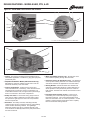
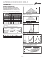
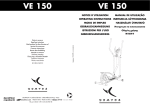
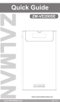
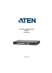
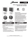
Electric Unit Heaters for Standard and Hazardous (Classified) Locations 2-116.5 • June, 2013 MODEL HER MODEL VE MODEL PTE MODEL HEX table of contents Table of Contents Page Electric Unit Heater Design Benefits Introduction..........................................................................................................3 Models HER, PTE, VE.........................................................................................4 Model HEX...........................................................................................................5 Performance/Dimensional Data Performance Data - All Units...............................................................................6 Performance Data - Vertical Unit Air Deflectors...................................................7 Dimensional Data - All Units................................................................................8 Accessories - Field Installed - All Units................................................................9 Ordering Information.................................................................................................10 Specifications - All Units..........................................................................................11 Selectable using the Modine Breeze TM AccuSpec Selection Software. As Modine Manufacturing Company has a continuous product improvement program, it reserves the right to change design and specifications without notice. 2 2-116.5 electric unit heaters Wide Range of Sizes and Types Horizontal air delivery unit heater type (HER series): 27 models, 7 sizes from 5 kW through 25 kW. Recommended for buildings with low ceilings, they are equipped with horizontal air deflector blades to adjust airflow either up or down. Optional vertical deflector blades are also available to deflect air to the right or left, providing complete directional control over discharge of heated air. Horizontal delivery units are normally placed around the perimeter of the building where heat loss is greatest, so that the air stream from each heater “wipes” the wall to produce a blanket of warm air along the outside walls. Vertical air delivery unit heater type (VE series): 21 models, 9 sizes from 5 kW through 50 kW. Recommended for buildings with high ceilings are high and where obstructions do not permit good horizontal movement of air. Various optional air deflectors are available to produce a variety of distribution patterns (see page 12). Vertical unit heaters are usually oriented so that the heat spread from one overlaps the heat spread of another unit heater. Power-Throw unit heater type (PTE series): 3 models, 3 sizes from 15 kW through 50 kW. For applications requiring heat throw greater than can be provided by HER units, Power-Throw unit heaters should be considered. For hard-to-heat areas, such as near frequently opened loading dock doors or large warehouses, Power-Throw units are frequently an ideal choice. They are equipped with horizontal air deflector blades to adjust airflow either up or down. Due to the higher velocity of discharge air, their air streams should not be directed at room occupants. A single Power-Throw unit heater can often be used to replace as many as three smaller horizontal delivery units, thereby reducing equipment, installation, and maintenance costs. TM TM TM TM Explosion Proof Horizontal Air Delivery Unit Heater Type (HEX series): WARNING Before installing and operating heaters confirm location, classification and properties of flammable vapors, liquids, gases, dusts and fibers which may be present. Each room, section or area should be considered individually. 26 model combinations, 9 sizes from 3 kW through 35 kW. These horizontal heaters are designed for rugged industrial applications in hazardous locations such as oil refineries, petrochemical plants, pulp and paper mills, coal mines, grain elevators, etc., where the possibility of explosion or fire exists due to the presence of flammable gases, vapors, powdered metals or dusts. Heaters are UL Listed for Class I, Divisions 1 & 2, Groups C and D; Class II, Division 1, Groups E, F and G, and Class II, Division 2, Groups F and G. The UL temperature code shall be T3B 329°F (165°C) for Class I and II, indicating maximum operating surface temperatures. Before selecting any heater for a particular application, refer to Article 500 of the National Electric Code, as well as other applicable Standards. Abbreviated descriptions of UL classes, groups, and divisions are as follows. Class I: Locations in which flammable gas or vapors may be present, such as, but not limited to: • Group C: Atmospheres such as ethylene, alcohol, carbon monoxide, or hydrogen sulfide. • Group D: Atmospheres such as acetone, gasoline, natural gas, propane or other gases or vapors of equivalent hazard. Class II: Locations in which combustible dusts may be present, such as, but not limited to: • Group E: Atmospheres containing combustible metal dust regardless of resistivity or other combustible dust of similar hazard characteristics. • Group F: Atmospheres containing carbon black, charcoal, coal or coke dust or dust of similar hazard characteristics. • Group G: Atmospheres containing flour, starch, grain dust or dusts of similar hazards. Division I: Location in which ignitable concentrations of flammable material exist under normal operating conditions. Division II: Locations in which flammable materials will normally be confined within closed containers and escape only in the case of abnormal conditions. Any equipment approved for Division I is automatically also approved for Division II. For further information, please consult the National Electric Code (NEC) and National Fire Prevention Association (NFPA) standards. Low Installation Cost Transformers, contactors and fuses are factory-furnished and factory-wired when required. Terminal blocks facilitate connection of power supply and control wiring. Modine electric unit heaters are lightweight and require no special reinforcement to suspend them. Easy to Service Fan and motor are exposed and can be removed without lowering the unit heater. A hinged bottom panel permits full access to controls on models HER, horizontal units. Vertical delivery and Power-Throw models have separate control boxes externally mounted on the units. Motors are totally enclosed, permanently lubricated, and thermally protected. Electrical contactors, fuses, and transformers are all safely enclosed in control compartments. TM Application Flexibility Total Heating Units can meet the total heating requirement in most industrial plants, commercial and recreational buildings, and in specialpurpose structures such as animal shelters. The features that make them the ideal selection for these types of buildings are a long heat throw, uniform heat delivery and low installation and maintenance costs. High up and out-of-the-way, unit heaters provide heat into work areas for clean, safe, economical heating comfort. Supplemental Heating They are ideal for spot heating applications during short periods of occupancy in the area to be heated. In out-of-theway locations, remote from areas served by the building’s main heating systems, electric unit heaters can often eliminate the expense of extending gas, steam, or hot water lines. Stand-by/Back-up Heating Where fossil fuel supplies are interruptible or undependable, electric unit heaters are recommended as a stand-by or back-up heating system to supply comfort to an entire building or any part of it. 2-116.5 3 DESIGN FEATURES - MODELS HER, PTE, & VE Figure 4.1 - Model HER & PTE Controls and Features ➃ ➆ ➀ ➇ ➁ ➄ ➇ ➈ ➂ ➂ ➃ ➄ and ➈ not shown, but located on back of PTE model. ➇ ➂ ➆ ➈ ➄ ➀ ➅ ➃ ➀ Casing - The casing is cleaned and phosphatized prior to electrostatic application of a baked-on, gray-green polyester powdercoat paint. ➁ Adjustable Air Deflector Blades (HER & PTE units only) Adjustable up and down, blades provide control over the horizontal air delivery of the unit heater. ➂ Control Compartment - Safely encloses power and control terminal blocks, contactor(s), fuses and transformer. Terminal blocks provide easy access for field wiring. On model HER horizontal units, a hinged bottom panel swings down for full access to the control compartment. ➃ Safety Fan Guard - Formed from heavy gauge steel rod stock, the fan guard is attached to the unit heater casing and provides a rigid support for the motor and protection from the exposed fan. ➄ Motor/Fan - The totally enclosed, thermally protected, continuous-duty motor is mounted to the fan guard utilizing rubber vibration absorbing material. The lightweight aluminum propeller type fan is connected directly to the motor shaft and is statically balanced for peak performance and low sound level. 4 ➅M otor Heat Shield (VE units only) - Protects the motor from heated air passing through the unit heater. ➆P rotective Screen (VE & PTE units only) - The aluminum screen protects heating elements from accidental damage and further enhances the appearance of the unit heater. ➇H eating Element - Nickel-chromium wire elements are enclosed in powder-filled aluminum coated steel tubes to which spiraled fins are permanently fused for maximum heat transfer. Elements are resistant to thermal shock and vibration. ➈ Automatic Reset Overheat Control - In the event of overheating, this control interrupts the power supply to the heating elements. The control automatically resets itself once the heater cools to a safe temperature. Control includes a switch located in terminal box with a capillary tube around bottom heating element. 2-116.5 DESIGN FEATURES - explosion-proof MODEL HEX Features Figure 5.1 - Model HEX Controls and Features 11 ➀ 12 ➁ ➂ ➉ 13 ➈ ➃ ➇ 15 ➄ ➆ 14 ➅ ➆ Factory wiring to tin plated copper bus bars for effective handling of high current flow. ➀ Epoxy coated 14 gauge steel cabinet contains heater core, motor, and fan assembly. All fasteners are plated for corrosion protection. ➇ Outer protective cover protects against high surface temperatures. ➁ Adjustable extruded aluminum louvers allow directional control of airflow. ➂ Liquid to air finned tube heat exchanger core. An Ethylene Glycol and water solution is used as the heat transfer fluid, providing freeze protection to -49°F (-45°C). A pressure relief valve protects the core from overpressure damage. Heaters are UL Listed for Class I, Divisions 1 & 2, Groups C and D, and Class II, Division 1, Groups E, F and G, and Class II, Division 2, Groups F and G. UL temperature code shall be T3B 329°F (165°C) for Class I and II, indicating maximum operating surface temperatures. Refer to page 3 for additional details. ➃ Low watt density metal sheathed immersion type heating elements in the liquid filled lower tank feature a Teflon® liner to keep elements away from outer surfaces. (Teflon® is a registered trademark of E.I du Pont de Nemours & Co.). ➄ The core is easily removable through the bottom of the heater for ease of service. ➅ Automatic reset, bimetal, high-limit provides over temperature protection and is rated for 100,000 cycles of service. ➈ Threaded explosion proof covers on junction boxes. ➉ NEMA Type 7 & 9 enclosures with large, heavy-duty aluminum data plate houses the built-in control transformer, convenient terminals for 120V room thermostat wiring connection, load carrying contactor with severe duty coil, and fuse protection for contactor coil, including a spare fuse in a convenient holder. 11 Narrow gap two-piece safety fan guard shields all moving parts. 12 Heavy gauge embossed fan blades. 13 Optional factory installed explosion proof thermostat. 14 Factory wired motor connections with copper conductor wires enclosed in steel conduit. Conduit is reverse threaded for easy motor removal. 15 Thermally protected, automatic reset explosion-proof motor Teflon® is a registered trademark of E.I du Pont de Nemours & Co. 2-116.5 5 PERFORMANCE DATA - ALL MODELS Heating Capacity Horizontal Delivery Vertical Delivery Horizontal Delivery Hazardous Locations (Explosion Proof) Standard Locations Location & Air Delivery Type High Stage Model HER 50 HER 75 HER100 HER125 HER150 HER200 HER250 PTE300 PTE400 PTE500 VE 50 VE 75 VE 100 VE 150 VE 200 VE 250 VE 300 VE 400 VE 500 HEX___-3 HEX___-5 HEX___-7.5 HEX___-10 HEX___-15 HEX___-20 HEX___-25 HEX___-30 HEX___-35 Air Data Low Stage kW Btu/hr kW Btu/hr Airflow (CFM) Temp Rise (°F) Heat Throw (ft.) Maximum Mounting Height (ft.) 5 7.5 10 12.5 15 20 25 30 40 50 5 7.5 10 15 19 25 30 40 50 3 5 7.5 10 15 20 25 30 35 17,100 25,600 34,100 42,700 51,200 68,200 85,300 102,400 136,500 170,600 17,100 25,600 34,100 51,200 64,800 85,300 102,400 136,500 170,600 10,250 17,050 25,600 34,100 51,200 68,250 85,300 102,350 119,450 n/a n/a n/a n/a n/a n/a n/a 15 20 25 n/a n/a n/a n/a n/a n/a 15 20 25 n/a n/a n/a n/a n/a n/a n/a n/a n/a n/a n/a n/a n/a n/a n/a n/a 51,200 68,200 85,300 n/a n/a n/a n/a n/a n/a 51,200 68,200 85,300 n/a n/a n/a n/a n/a n/a n/a n/a n/a 530 530 830 830 830 1300 1300 2575 2575 2575 800 800 940 1340 1600 1600 2575 2575 2575 500 500 850 850 1750 1750 3600 3600 3950 30 45 38 48 57 49 61 40 54 70 21 31 36 38 41 55 40 54 70 19 31.6 27.9 37.2 27.1 36.1 21.9 26.3 28 14 14 20 20 20 25 25 75 60 45 8 8 9 10 10 11 12 17 15 14 See Table 7.1 for Throw/Mounting Height Data. 15 15 30 30 40 40 70 70 70 7 7 10 10 10 10 20 20 20 Table 6.2 - Unit Electrical Amp Draw and Motor Data - All Models Model HER 50 HER 75 HER 100 HER 125 HER 150 HER 200 HER 250 PTE300 PTE400 PTE500 VE 50 VE 75 VE 100 VE 150 VE 200 VE 250 VE 300 VE 400 VE 500 HEX412- ➄ 60-3.0 HEX412- ➄ 60-5.0 HEX412- ➄ 60-7.5 HEX412- ➄ 60-10.0 HEX416- ➄ 60-15.0 HEX416- ➄ 60-20.0 HEX420- ➄ 60-25.0 HEX420- ➄ 60-30.0 HEX420- ➄ 60-35.0 11 208V/1ph 24.5 36.5 49.4 14.4 24.0 36.1 - Power Code, Supply Voltage (60Hz) 12 240V/1ph 21.3 31.7 42.9 21.4 31.9 42.3 12.5 20.8 31.3 41.7 - 31 208V/3ph 14.3 21.3 29.0 36.0 42.9 56.8 70.7 14.5 21.4 28.3 42.5 8.3 13.9 20.8 27.8 - 32 240V/3ph 12.5 18.5 25.3 31.4 37.4 49.4 61.4 12.7 18.6 24.6 37.0 49.0 7.2 12.0 18.0 24.1 36.1 - 33 480V/3ph 6.5 9.5 13.3 16.3 19.3 25.3 31.4 37.6 / 19.5 ➃ 49.6 / 25.5 ➃ 61.5 / 31.5 ➃ 6.7 9.7 12.7 19.0 25.0 31.0 37.6 / 19.5 ➃ 49.6 / 25.5 ➃ 61.5 / 31.5 ➃ 3.6 6.0 9.0 12.0 18.0 24.1 30.1 36.1 42.1 ➀ Airflow shown is at 70°F ambient and heating at full rated capacity. ➁F or HER, airflow CFM is for inlet. For PTE and VE, airflow CFM is outlet. ➂F or HEX units above 6000 feet above sea level, altitude limits may exist. Refer to the latest revision of Installation & Service Manual 2-519. Motor Information Motor HP Motor Type Motor Bearing Type 1/40 Totally Enclosed, Shaded Pole Sleeve 1/6 Totally Enclosed, Permanent Split Capacitor Ball 1/15 Totally Enclosed, Shaded Pole Sleeve Totally Enclosed, Permanent Split Capacitor Ball Explosion Proof Ball 1/15 1/8 1/6 1/2 ➃ When two amp draws are shown, the first is at high stage heat, the second is at low stage heat. ➄ The four missing digits indicate voltage and phase. Example: A 480V/3ph HEX model with 30kW rating would have a full model number of HEX420-480360-30.0. 6 Refer to Table 10.1 for a complete listing of full model numbers available. 2-116.5 HEAT SPREAD AND MOUNTING HEIGHT - MODEL VE Performance Data Figure 7.2 - Without Deflector Heat Spread and Mounting Height Refer to Table 7.1 and Figures 7.2 through 7.5 for the recommended mounting heights and accompanying heat spread of vertical units without an air deflector and with the three air deflectors offered. H Table 7.1 - Heat Spread and Mounting Height (Ft.) ➀ With No Deflector Truncone Model Max. Spread No. Height (S) VE 50 VE 75 VE100 VE150 VE200 VE250 VE300 VE400 VE500 13 11 12 17 20 17 20 18 16 20 17 18 26 30 26 31 27 24 S With Deflector Louvers Cone-Jet Vertical➂ Figure 7.3 - With Truncone 45°➂ Vertical➂ H S H S H S H S 9 8 8 11 13 11 15 13 12 24 20 22 30 36 31 36 32 29 18 15 17 23 27 23 28 24 22 23 20 22 30 35 31 36 32 29 15 13 14 20 23 20 24 21 19 13 11 12 17 20 18 21 18 16 8 8 8 10 12 10 12 11 10 23 20 22 30 35 31 36 32 29 ➀ With 70°F ambient air and heating at full capacity ➁ Indicates pitch of adjustable louvers. 45° louvers are available for one- or two-way deflection H S Figure 7.4 - With Cone-Jet Figure 7.1 - Vertical Air Outlet Accessories CONE-JET TRUNCONE M X H LOUVER L T P Z Table 7.2 - Vertical Air Outlet Accessories S Figure 7.5 - With One- or Two-Way Louvers Vertical Model Truncone Cone-JetLouvers No. MXL T P Z VE50-VE250 12 1/2 22 6 1/2 18 7/8 6 1/2 16 7/8 VE300-VE-500 12 1/2 27 7 1/2 24 3/4 7 1/2 19 3/4 One-Way H S Two-Way H H S S Figure 7.6 - Mounting Height & Heat Throw Models HER, PTE, & HEX (refer to Table 6.1) T H 2-116.5 7 DIMENSIONAL DATA - ALL MODELS Dimensional Data Figure 8.1 - Model HER Dimensions (inches) Figure 8.3 - Model VE Dimensions (inches) (4) MTG HOLES 1/2 — 13 N.C. TAP B CEILING 18” MIN G H B E F C SIDE VIEW D DIAMETER MINIMUM CLEARANCES: AT LEAST 18" FROM CEILING AND 24" HORIZONTALLY FROM NEAREST ENCLOSURE. KNOCKOUTS FOR POWER SUPPLY AND CONTROL WIRES. TOP VIEW MODELS VE50 THROUGH VE250 SHOWN Model Dim. VE50 VE75VE100VE150VE200VE250VE300VE400VE500 B C E D F G H 11 3/8 11 3/8 11 3/8 11 3/8 11 3/8 11 3/8 18 3/8 18 3/8 18 3/8 24 7/8 24 7/8 24 7/8 24 7/8 24 7/8 24 7/8 34 7/8 34 7/8 34 7/8 4 3/4 2 1/8 14 1/2 14 1/2 14 1/2 14 1/2 14 1/2 14 1/2 19 1/2 19 1/2 4 1/4 4 1/4 4 3/4 4 3/4 4 3/4 6 1/4 6 1/4 5 4 3/4 4 3/4 6 1/4 5 4 3/4 4 3/4 6 1/4 5 4 3/4 4 3/4 6 1/4 5 4 3/4 4 3/4 6 1/4 8 5/8 2 1/8 4 3/4 6 1/4 19 1/2 8 5/8 8 5/8 2 1/8 4 3/4 4 3/4 6 1/4 6 1/4 Fan Dia. 141414141414191919 Wt. Lbs. ➀ Figure 8.4 - Model HEX Dimensions (inches) 52 ➀52 ➀67 ➀65 ➀74 ➀97 ➀98 ➀ DIMENSIONS (INCHES) ➀ 24 5/8" MAX. MODEL SIZE (kW RATING) DIM. 3-10 15-20 A 8-1/16 6-11/16 7-1/16 B 18-3/16 22-3/16 26-3/16 C 24-5/8 28-5/8 32-5/8 D 18-1/2 22-1/2 26-1/2 E 19-7/16 23-7/16 27-7/16 25-35 QTY (2) 9/16" MOUNTING HOLES ➀ ±1/8" EXCEPT "C" WHICH IS ±5/16" Model Operating Shipping Size Weight Weight ➀ Approximate Shipping Weight Add 7 lbs. for 480 Volt Models. A 10 3/8" ±3/16" 5/8" B HER50 HER75HER100HER125HER150HER200HER250 16-7/8 16-7/8 16-7/816-7/816-7/818-7/818-7/8 20-7/820-7/8 20-7/8 20-7/8 20-7/8 24 24 14-3/414-3/4 14-3/4 14-3/4 14-3/4 20 20 14-1/2 14-1/2 14-1/214-1/214-1/216-1/216-1/2 13 13 1313131616 8-7/88-7/8 9-5/8 9-5/8 9-5/8 12-5/8 12-5/8 13-1/2 13-1/2 13-1/213-1/213-1/215-1/215-1/2 20-1/4 20-1/4 21-1/421-1/421-1/426-1/226-1/2 2-1/4 2-1/4 2-1/42-1/42-1/43-1/43-1/4 3-1/4 3-1/4 3-1/43-1/43-1/44-1/44-1/4 2-1/4 2-1/4 2-1/42-1/42-1/42-1/22-1/2 12-3/4 12-3/4 12-3/412-3/412-3/414-1/214-1/2 12 12 1212121414 Approx. Wt. Lbs. 626466 70 7273122125129 C Dim. A B C D E F G H K L M O Fan Dia. Model 2 15/16" ±1/4" HEX412111 151 Figure 8.2 - Model PTE Dimensions (inches) HEX416 133 173 HEX420 154 204 7 7/16" ±3/8" 15 20 D 80 25 70 8 2-116.5 60 1 1/2" MAX. 10 50 5°C 40 °F 15 3/4" ±3/16" E 1"NPT (FOR FIELD WIRING) ACCESSORIES - FIELD INSTALLED Thermostats Vertical Unit Air Deflectors (refer to page 7 for more info) Other thermostats offered (not unit-mounted) are: • • The unit-mounted thermostat in Figure 9.1 is provided as a field installed kit for a model HER series only. Temperature range of the dial setting is from 40°F to 90°F. • Line-voltage single stage • Low-voltage single stage (requires Low-Voltage Control kit.) • Line-voltage, 2-stage (available on PTE and VE models 300, 400 and 500) Figure 9.1 - Unit-Mounted Thermostat • • The cone-jet allows the discharge air stream to be adjusted from a concentrated high velocity jet to a broadened air stream to cover a larger area. The truncone causes a broad discharge air stream covering a larger area than possible with the cone-jet. The one-way louver allows the discharge air stream to be adjusted in one direction. The two-way louver allows the discharge air stream to be adjusted in two directions. Pipe Suspension Adapter Kit To facilitate threaded-pipe suspension mounting, a pipe-adapter kit is available that includes two drilled pipe caps and two 3/8 - 16 x 1 1/2" capscrews. One kit is required to pipe-mount HER series and two kits must be ordered to mount VE series unit heaters. (On models VE50 through VE250 supplied with 480 volt, 3 phase service, clearance is not adequate for utilization of this kit.) This kit cannot be used with Power-Throw (PTE series) unit heaters. TM Wall Mounting Bracket Low-Voltage Control This control permits use of a low-voltage thermostat control of electric unit heaters. High capacity models VE300, VE400, VE500 and all PTE series heaters cannot operate in two stages with a low-voltage thermostat; however, they will respond in one stage with full operation of all elements. On model HER series, this control cannot be combined with the unit-mounted thermostat. Summer-Winter Switch For easier unit installation, where ceiling suspension is not feasible, a wall-mounting bracket is available for models HER50 through HER250 and PTE300 through PTE500. The one-point suspension illustrated in Figure 9.4 permits swiveling the unit 90° horizontally for most effective air flow direction. Fasteners for mounting to wall are not furnished. Figure 9.4 Wall Mounting Bracket In the winter position, the thermostat will cycle the fan and heating elements. In the summer position, the switch will permit the fan to run continuously while the heating elements are controlled by the thermostat. Maximum switch rating is 10A at 250 volts. Kit includes switch, conduit box, wire nuts, and installation instructions. Figure 9.5 HEX Mounting Kits ➀ HMK Figure 9.3 Summer-Winter Switch Figure 9.2 Low-Voltage Control Hanging Mounting Kit (HMK) ➀ WMK Simple and economical if adequate overhead structure exists. Requires 1/2" pipe, cut and threaded (not supplied) Wall Mounting Kit (WMK) ➀ Vertical Unit Air Deflector Blades Blades used to deflect airflow in directions left or right of unit heater. Used in addition to standard horizontal deflector blades. Not available for Power-Throw models. TM Ideal for use in buildings that have substantial walls. the Z sections provide additional support where necessary. Basic Mounting Kit (BMK) ➀ Suitable for applications where the support arm can be bolted or welded directly to structural steel or concrete. 2-116.5 BMK ➀ Available for HEX models only. 9 UNIT SELECTION - ALL MODELS To order a Modine electric unit heater, specify: 1. Model Number: HER - Horizontal Electric Unit Heater VE - Vertical Electric Unit Heater PTE - Power-Throw Horizontal Electric Unit Heater TM HEX - Horizontal Explosion Proof Electric Unit Heater 2. Select the full model number from Table 10.1 by locating the model series from Step 1 within Table 10.1 at the intersection of the kW rating and supply voltage required. If that selection shows "-", then there is not a model available matching those parameters. 3. Add any required accessories as shown on page 7 and 9. Table 10.1 - Full Model Number Selection Horizontal Air Delivery 240V/1ph 11 5 240V/3ph 480V/3ph 12 31 32 33 HER 50B 1101 HER 50B 1201 HER 50B 3101 HER 50B 3201 HER 50B 3301 10 HER100B 1101 HER100B 1201 HER100B 3101 HER100B 3201 HER100B 3301 15 - - HER150B 3101 HER150B 3201 HER150B 3301 kW Rating 7.5 12.5 20 25 30 40 Horizontal Air Delivery Hazardous Locations (Explosion Proof) HER 75B 1101 - - - - - 50 - 7.5 - 15 - 10 20 25 30 40 50 - HER 75B 1201 - - HER 75B 3101 HER125B 3101 HER200B 3101 HER 75B 3201 HER125B 3201 HER200B 3201 HER250B 3301 - - - PTE400B 3301 - - - VE 50B 1201 VE 75B 1201 - VE 50B 3101 VE 75B 3101 - PTE500B 3301 VE 75B 3201 VE 75B 3301 VE 100B 1201 VE 100B 3101 VE 100B 3201 VE 100B 3301 - - - VE 200B 3201 VE 200B 3301 - - VE 150B 3101 - - - - - - - VE 150B 3201 - 7.5 HEX412-208160-7.5 HEX412-240160-7.5 HEX412-208360-7.5 HEX412-240360-7.5 25 30 VE 50B 3301 - HEX412-240360-3.0 20 PTE300B 3301 - VE 50B 3201 HEX412-208360-3.0 15 HER200B 3301 HER250B 3201 HEX412-240160-3.0 10 HER125B 3301 HER250B 3101 HEX412-208160-3.0 5 HER 75B 3301 - 3 35 10 Supply Voltage and Power Code 208V/3ph 5 Vertical Air Delivery Standard Locations Electric Unit Heater Type 208V/1ph HEX412-208160-5.0 HEX412-240160-5.0 HEX412-208360-5.0 HEX412-240360-5.0 VE 150B 3301 VE 250B 3301 VE 300B 3301 VE 400B 3301 VE 500B 3301 HEX412-480360-3.0 HEX412-480360-5.0 HEX412-480360-7.5 - HEX412-240160-10.0 HEX412-208360-10.0 HEX412-240360-10.0 HEX412-480360-10.0 - - - - HEX416-480360-20.0 - - - - - HEX416-208360-15.0 - - - - - 2-116.5 HEX416-240360-15.0 - - - HEX416-480360-15.0 HEX420-480360-25.0 HEX420-480360-30.0 HEX420-480360-35.0 Specifications - ALL MODELS A. Standards blended, long-life solution of ethylene-glycol, water, and corrosion inhibitors. The heat exchanger shall have three heavy-duty immersion heating elements brazed into a heavy steel bulkhead. The elements shall consist of high-quality resistance wire embedded in a compacted magnesium oxide refractory and sheathed in metal tubing. The heater is to be protected by a snap-action bimetal temperature high-limit, which shall not be affected by altitude or changes in atmospheric pressure. The high-limit shall be an automatic reset type, and will shut off the heater if the exchanger temperature rises due to a lack of heat dissipation. A.1.a. Units shall be UL and C-UL listed for safe operation, construction, and performance. Units shall be listed for use in both the U.S. and Canada for commercial and industrial installations. (Models HER, VE, and PTE) A.1.b. Explosion proof units, model HEX4 shall be UL listed and CSA certified for use in the following hazardous areas: • Class I, Divisions 1 & 2, Groups C & D • Class II, Division 1, Groups E, F & G • Class II, Division 2, Groups F & G • Class I, Zones 1 & 2, Group IIA & IIB Units shall be rated for National Electrical Code and Canadian Electrical Code Temperature Code T3B 165°C (329°F). E. Motor and Propeller Fan B. Mechanical Configuration B.1.a. Heater shall be a Modine model HER horizontal air delivery electric unit heater of the size, capacity, and voltage as listed in the equipment schedule. B.1.b. Heater shall be a Modine Power-Throw model PTE horizontal air delivery electric unit heater of the size, capacity, and voltage as listed in the equipment schedule. B.1.c. Heater shall be a Modine model VE vertical air delivery electric unit heater of the size, capacity, and voltage as listed in the equipment schedule. B.1.d. Heater shall be a Modine model HEX4 horizontal air delivery electric unit heater of the size, capacity, and voltage as listed in the equipment schedule. TM C. Unit Casing C.1. Unit shall have a steel casing that is treated for corrosion resistance and painted with an electrostatically applied, baked on, gray-green polyester powdercoat paint finish. (Models HER, VE, and PTE) C.2.a. Model HER unit shall have a squared corner casing and the top shall have two threaded holes (3/8" - 16 TAP) for threaded rod suspension. The bottom of casing shall have a hinged panel for service access to wiring and controls. C.2.b.Model PTE unit shall consist of two circular steel covers bolted together with the heating element supports. The air discharge side cover shall have a die-formed fan venturi. The back cover shall have a depression for motor mounting with openings for cooling-air circulation for the motor. Four hanging brackets shall be provided for use with 5/8” diameter suspension rods. C.2.c.Model VE unit shall consist of two circular steel covers bolted together with the heating element supports. The bottom cover shall have a die-formed fan venturi. The top cover shall include an inner cone for motor mounting and to provide a heat shield from radiant and convective heat from the heating elements. C.2.d. Model HEX4 shall be fabricated from 14 gauge steel with a baked epoxy powder coating over a 5-stage pretreatment including iron phosphate, for protection from corrosive atmospheres. The cabinet shall include two (2) 9/16” mounting holes located on the top. D. Heating Elements D.1.a. Elements shall consist of a nickel-chromium resistance wire surrounded with magnesium oxide and sheathed in steel spiral-finned tubes. Elements shall have kilowatt rating as listed in the equipment schedule. (Models HER, VE, and PTE) D.1.b. The heat exchanger shall be fluid-to-air type consisting of steel tubes with roll-formed aluminum fins and be vacuum charged. The heat exchanger shall be protected by a preset 100 psig (690 kPa) pressure-relief valve, aluminum body, no serviceable parts. The heat exchanger shall be filled to design level with a custom- E.1.a. Each unit shall have a single 208-230V/60Hz/1ph motor. The motor shall be totally enclosed, continuous-duty, with automatic resetting, thermal-overload protection. Propeller fan shall be directly connected to the motor shaft and be statically balanced. The motor shall be mounted to the unit with rubber vibration absorbing material. (Models HER, VE, and PTE) E.1.b. Each unit shall have a ball bearing, permanently lubricated, thermally protected explosion-proof motor rated for continuous duty. The fan blades shall be aluminum to prevent sparking. Propeller fan shall be directly connected to the motor shaft and be statically balanced. The fan shall be shielded with a heavy-duty epoxy coated guard of two piece construction to provide easy maintenance and cleaning of the fan and motor. The guard shall not allow a 1/4" or larger probe to enter. (Model HEX4 only) F. Electrical F.1. All units shall have built-in contactors and control circuit transformers (where required) to provide single-source power connection. F.1.a. Models VE and PTE, sizes 300 through 500 shall have two sets of contactors to provide for two-stage operation. F.1.b. Model HEX4 shall have a contactor coil that is encapsulated severe duty and separately fuse-protected. F.2. Fuse blocks and factory-supplied fuses shall be installed on all models except HER 50 and HER 75 with 208 volt or 230-volt single or 3-phase power supply. A wiring diagram and grounding lug shall be included in each control compartment. F.3.a. Transformers shall be factory installed on all models with 460 volt, 3 phase power supply to permit 230 volt motor operation. (Models HER, VE, and PTE) F.3.b. Transformers shall be factory installed on all HEX4 models with the primary voltage being the same as the heater voltage and the secondary being 120V grounded circuit. F.4. Electrical control components shall be safely enclosed in a separate junction box. A wiring diagram and a grounding lug shall be included in each power junction box. F.4.a. The Model HEX4 control center shall be enclosed in an explosion-proof control enclosure with a large threaded cover for easy access. The control center shall include a printed circuit board with a terminal block for room thermostat connection and in-line fuse protection, with both an operating fuse and a spare fuse. F.5. (opt) The HEX4 heater shall be supplied with a built-in explosion-proof room thermostat mounted on the control enclosure side of the heater. G. Air Deflectors G.1.a. Adjustable horizontal air deflectors shall be furnished. (Models HER and PTE) G.1.b. Louvers shall be individually adjustable and made of anodized extruded aluminum. (Model HEX4) 2-116.5 11 The Modine brand has been the industry standard since Arthur B. Modine invented and patented the first lightweight, suspended hydronic unit heater in 1923. No other manufacturer can provide the combined application Products from Modine are designed to provide indoor air-comfort and ventilation solutions for residential, commercial, institutional and industrial applications. Whatever your heating, ventilating and air conditioning requirements, Modine has the product to satisfy your needs, including: HVAC •Unit Heaters: –Gas –Hydronic –Electric –Oil •Ceiling Cassettes •Duct Furnaces flexibility, technical expertise and •Hydronic Cabinet Unit Heaters, Fin Tube, Convectors fast delivery found at Modine. •Infrared Heaters Consult your local Modine distributor for help in solving your indoor air problems. •Make-up Air Systems •Unit Ventilators Ventilation •Packaged Rooftop Ventilation School Products •Vertical Packaged Classroom HVAC: – DX Cooling/Heat Pump – Water/Ground Source Heat Pump – Horizontal/Vertical Unit Ventilators Geothermal •Water-to-Water •Water-to-Air •Combination Specific catalogs are available for each product. Catalogs 75-136 and 75-137 provide details on all Modine HVAC equipment. Modine Manufacturing Company 1500 DeKoven Avenue Racine, Wisconsin 53403-2552 Phone: 1.800.828.4328 (HEAT) www.modinehvac.com © Modine Manufacturing Company 2013