1
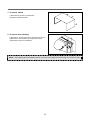
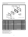
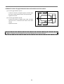
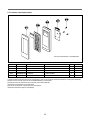
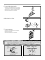
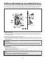
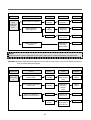
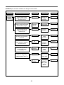
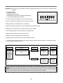
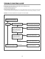
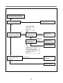
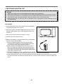
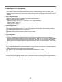
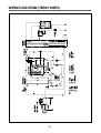
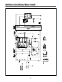
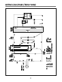
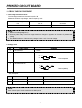
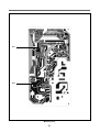
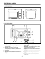
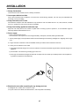
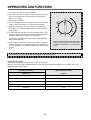
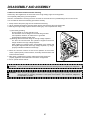
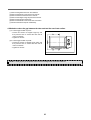
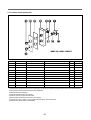
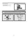
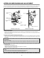
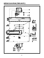
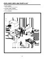
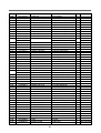
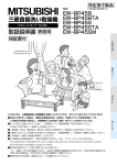
Turbo Air Inc.
1250 VICTORIA ST.
CARSON, CA 90746, USA
PRINTED DATE: May. 2003
S/M No. :
S/M No. :
Service Manual
Microwave Oven
Model: TMW-1100E
TMW-1100EC
TMW-1100M
TMW-1100MC
TMW-800T
TMW-800TC
http://www.turboairinc.com
May. 2003
PRECAUTIONS TO BE OBSERVED BEFORE AND
DURING SERVICING TO AVOID POSSIBLE
EXPOSURE TO EXCESSIVE MICROWAVE ENERGY
(a) Do not operate or allow the oven to be operated with the door open.
(b) Make the following safety checks on all ovens to be serviced before activating the magnetron or other
microwave source, and make repairs if necessary: (1) Interlock operation, (2) Proper door closing, (3)
Seal and sealing surfaces (arcing, wear, and other damage), (4) Damage to or loosening of hinges and
latches (5) Evidence of dropping or abuse.
(c) Before turning on power to the microwave oven for any service test or inspection within the microwave
generating compartments, check the magnetron, wave guide or transmission line, and cavity for proper
alignment, integrity, and connections.
(d) Any defective or misadjusted components in the interlock, monitor, door seal and microwave
generation and transmission systems shall be repaired, replaced, or adjusted by procedures described
in this manual before the oven is released to the owner.
(e) A microwave leakage check to verify compliance with the Federal performance standard should be
performed on each oven prior to release to the owner.
TABLE OF CONTENTS
TMW-1100E / TMW-1100EC / TMW-1100M / TMW-1100MC
SAFETY AND PRECAUTIONS..................................................................................................................................................3
FOR SAFE OPERATION.....................................................................................................................................................3
FOR SAFE SERVICE PROCEDURES ...............................................................................................................................3
SPECIFICATIONS ......................................................................................................................................................................4
EXTERNAL VIEW.......................................................................................................................................................................5
OUTER DIMENSION...........................................................................................................................................................5
FEATURE DIAGRAM ..........................................................................................................................................................6
CONTROL PANEL...............................................................................................................................................................7
INSTALLATION ..........................................................................................................................................................................8
OPERATIONS AND FUNCTIONS .............................................................................................................................................9
DISASSEMBLY AND ASSEMBLY ..........................................................................................................................................11
INTERLOCK MECHANISM AND ADJUSTMENT...................................................................................................................19
TROUBLE SHOOTING GUIDE ................................................................................................................................................20
MEASUREMENT AND TEST...................................................................................................................................................27
MEASUREMENT OF THE MICROWAVE POWER OUTPUT .........................................................................................27
MICROWAVE RADIATION TEST .....................................................................................................................................28
COMPONENT TEST PROCEDURE.................................................................................................................................29
WIRING DIAGRAM...................................................................................................................................................................30
PRINTED CIRCUIT BOARD.....................................................................................................................................................34
CIRCUIT CHECK PROCEDURE ......................................................................................................................................34
PCB CIRCUIT DIAGRAM..................................................................................................................................................37
P.C.B. LOCATION NO.......................................................................................................................................................38
EXPLODED VIEW AND PARTS LIST .....................................................................................................................................39
DOOR ASSEMBLY............................................................................................................................................................39
CONTROL PANEL ASSEMBLY........................................................................................................................................39
TOTAL ASSEMBLY...........................................................................................................................................................39
1
TMW-800T / TMW-800TC
SPECIFICATIONS .............................................................................................................................................................43
EXTERNAL VIEW..............................................................................................................................................................44
1. OUTER DIMENSION.......................................................................................................................................44
2. FEATURE DIAGRAM ......................................................................................................................................44
INSTALLATION .................................................................................................................................................................45
OPERATIONS AND FUNCTIONS.....................................................................................................................................46
DISASSEMBLY AND ASSEMBLY....................................................................................................................................47
INTERLOCK MECHANISM AND ADJUSTMENT.............................................................................................................54
TROUBLE SHOOTING GUIDE .........................................................................................................................................55
MEASUREMENT AND TEST ............................................................................................................................................57
1. MEASUREMENT OF THE MICROWAVE POWER OUTPUT ........................................................................57
2. MICROWAVE RADIATION TEST ...................................................................................................................58
3. COMPONENT TEST PROCEDURE ...............................................................................................................59
WIRING DIAGRAM............................................................................................................................................................60
EXPLODED VIEW AND PARTS LIST...............................................................................................................................62
1. DOOR ASSEMBLY .........................................................................................................................................62
2. CONTROL PANEL ASSEMBLY......................................................................................................................62
3. TOTAL ASSEMBLY.........................................................................................................................................62
2
SAFETY AND PRECAUTIONS
CAUTION : This Device is to be Serviced Only by Properly Qualified Service Personnel. Consult the Service
Manual for Proper Service Procedures to Assure Continued Safety Operation and for Precautions
to be Taken to Avoid Possible Exposure to Excessive Microwave Energy.
1. FOR SAFE OPERATION
Damage that allows the microwave energy (that cooks or heats the food) to escape will result in poor cooking and
may cause serious bodily injury to the operator.
IF ANY OF THE FOLLOWING CONDITIONS EXIST, OPERATOR MUST NOT USE THE APPLIANCE.
(Only a trained service personnel should make repairs.)
1) A broken door hinge.
2) A broken door viewing screen.
3) A broken front panel, oven cavity.
4) A loosened door lock.
5) A broken door lock.
The door gasket plate and oven cavity surface should be kept clean.
No grease, soil or spatter should be allowed to build up on these surfaces or inside the oven.
DO NOT ATTEMPT TO OPERATE THIS APPLIANCE WITH THE DOOR OPEN. The microwave oven has
concealed switches to make sure the power is turned off when the door is opened. Do not attempt to by-pass.
DO NOT ATTEMPT TO SERVICE THIS APPLIANCE UNTIL YOU HAVE READ THIS SERVICE MANUAL.
2. FOR SAFE SERVICE PROCEDURES
1) If the oven is operative prior to servicing, a microwave emission check should be performed prior to servicing
the oven.
2) If any certified oven unit is found to servicing, a microwave emission check should be performed prior to
servicing the oven.
(a) inform the manufacturer, importer or assembler,
(b) repair the unit at no cost to the owner,
(c) attempt to ascertain the cause of the excessive leakage,
(d) tell the owner of the unit not to use the unit until the oven has been brought into compliance.
3) If the oven operates with the door open, the service person should tell the user not to operate the oven and
contact the manufacturer and CDRH immediately.
CAUTION
MICROWAVE RADIATION
PERSONNEL SHOULD NOT BE EXPOSED TO THE MICROWAVE ENERGY WHICH MAY RADIATE
FROM THE MAGNETRON OR OTHER MICROWAVE GENERATING DEVICE IF IT IS IMPROPERLY
USED OR CONNECTED. ALL INPUT AND OUTPUT MICROWAVE CONNECTIONS. WAVEGUIDES
FLANGES AND GASKETS MUST BE SECURED. NEVER OPERATE THE DEVICE WITHOUT A
MICROWAVE ENERGY ABSORBING LOAD ATTACHED. NEVER LOOK INTO AN OPEN WAVEGUIDE
OR ANTENNA WHILE THE DEVICE IS ENERGIZED.
3
SPECIFICATIONS
MODEL
TMW-1100E / TMW-1100EC
POWER SUPPLY
POWER
CONSUMPTION
120V~60HZ, SINGLE PHASE WITH GROUND
MICROWAVE
1500 W / 1600 W
GRILL
COMBINATION
MICROWAVE ENERGY OUTPUT
1100 W
MICROWAVE FREQUENCY
2450MHz
OUTSIDE DIMENSIONS (W X H X D)
560X344X483mm (22.0X13.5X19 in.)
CAVITY DIMENSIONS (W X H X D)
369X221X400mm (14.5X8.7X15.7 in.)
NET WEIGHT
APPROX. 16.5kg (36.4lbs)
TIMER
59min. 99sec.
FUNCTION SELECTIONS
MICROWAVE
POWER SELECTIONS
4 LEVELS
CAVITY VOLUME
1.2 Cu. Ft
* Specifications are subject to change without notice.
MODEL
TMW-1100M / TMW-1100MC
POWER SUPPLY
POWER
CONSUMPTION
120V~60HZ, SINGLE PHASE WITH GROUND
MICROWAVE
1500 W / 1600 W
GRILL
COMBINATION
MICROWAVE ENERGY OUTPUT
1100 W
MICROWAVE FREQUENCY
2450MHz
OUTSIDE DIMENSIONS (W X H X D)
560X344X483mm (22.0X13.5X19 in.)
CAVITY DIMENSIONS (W X H X D)
369X221X400mm (14.5X8.7X15.7 in.)
NET WEIGHT
APPROX. 16.5kg (36.4lbs)
TIMER
10min. Single Speed
FUNCTION SELECTIONS
MICROWAVE
POWER SELECTIONS
5 LEVELS
CAVITY VOLUME
1.2 Cu. Ft
* Specifications are subject to change without notice.
4
EXTERNAL VIEW (ELECTRICAL)
1. OUTER DIMENSION
483
344
560
2. FEATURE DIAGRAM
3
5
2
4
7
8
1
6
1 Safety interlock system
2 Door viewing screen - Allows viewing of food. The screen is designed so that light can pass through, but not the
radiation.
3 Door hook - If the door is opened while the oven is operating, it will automatically shoot off.
4 Oven cavity
5 Door seal - Door seal maintains the microwave energy within the oven cavity.
6 Glass tray - Made of special heat resistant glass. Food in a proper receptacle is placed on this tray for cooking.
7 Stirrer cover - This is located on the ceiling with the stirrer fan.
8 Inlet cover - Protect the air inlet from splattering of foods being cooked.
5
3. CONTROL PANEL
2
PROGRAM
DEFROST
5
6
11
1
12
2
13
3
14
4
15
5
16
6
17
7
18
8
19
9
20
CHECK
DOUBLE
QUANTITY
STOP/CLEAR
1
3
4
10
POWER
7
START/+30SEC
8
9
1 Display - Cooking time, power level, indicators are displayed.
2 Program - Used to save cooking data.
3 Defrost - Used to defrost foods.
4 Time Set Pad - Used to set the cooking time or cook preprogrammed foods.
5 Check - Used to check cooking data.
6 Double Quantity - Used to extend programmed cooking time.
7 Power - Used to set power level.
8 Stop/Clear - Used to stop the oven operation or to delete the cooking data.
9 Start/+30sec - Used to start the oven and also used to set a reheat time.
6
EXTERNAL VIEW (MECHANICAL)
1-1. OUTER DIMENSION
483
344
560
2-1. FEATURE DIAGRAM
3
5
4
7
10
1
8
9
2
6
6. Glass cooking tray - Made of special heat resistant
glass. Food in a proper receptacle is placed on this
tray for cooking.
1. Safety interlock system
2. Door viewing screen - Allows viewing of food. The
screen is designed so that light can pass through, but
not the radiation.
7. Cover Stirrer - Protects the microwave outlet from
splattering of foods being cooked.
3. Door hook - If the door is opened while the oven is
operating, it will automatically shoout off.
8. Knob V.P.C - Used to select a microwave power level.
9. Knob timer - Used in setting cooking time for all
function.
4. Oven cavity
5. Door seal - Door seal maintains the microwave energy
within the oven cavity .
10. Inlet cover - Protects the air inlet from splattering of
foods being cooked.
7
INSTALLATION
1. Steady, flat location.
This microwave oven should be set on a steady, flat surface.
2. Leave space behind and side.
All air vents should be kept clear. If all vents are covered during operation, the oven may be overheated and,
eventually, cause oven failure.
3. Away from radio, and TV sets
Poor television reception and radio interference may result if the oven is located close to a TV, radio, antenna, or
feeder and so on. Position the oven as far from them as possible.
4. Away from heating appliances and water taps
Keep the oven away from hot air, steam or splash when choosing a place to position it, or the insulation might be
adversely affected and breakdowns occur.
5. Power supply
• Check your local power source.
This microwave oven requires a current of approximately 14.5 amperes, 120Volts, 60Hz grounded outlet.
1. A short power-supply cord is provided to reduce the risks resulting from becoming entangled in or trippping over a
longer cord.
2. Longer cord sets or extension cords are available and may be used if care is exercised in their use.
3. If a long cord or extension cord is used:
1) The marked electrical rating of the cord set or extension cord should be at least as great as the electrical rating
of the appliance.
2) The extension cord must be a grounding type 3-wire cord.
3) The longer cord should be arranged so that it will not drape over the counter top or tabletop where it can be
pulled on by children or tripped over unintentionally.
6. Examine the oven after unpacking for any damage such as:
A misaligned door, broken door or a dent in cavity.
If any of the above are visible, DO NOT INSTALL, and notify dealer immediately.
8
OPERATIONS AND FUNCTIONS (ELECTRICAL)
1. Connect the main lead to an electrical outlet.
2. After placing the food in a suitable container, open the oven door and put it on the glass tray. The glass tray must
always be in place during cooking.
3. Close the door securely.
4. The oven door can be opened at any time during operation by touching the door release button on the control
panel.
The oven will automatically shut off. To restart the oven, close the door and then touch START.
5. Each time the pad is touched, a BEEP will sound to acknowledge the touch.
6. The oven automatically cooks on full power unless set to a lower power level.
7. The display will show : 0 when the oven is plugged in.
8. When the STOP/CLEAR pad is touched during the oven operation, the oven stops cooking and all information
retained.
To erase all information touch, the STOP/CLEAR pad once more. If the oven door is opened during the oven
operation, all information is retained.
9. If the START pad is touched and the oven does not operate, check the area between the door and door is closed
securely. The oven will not start cooking until the door is completely closed or the program has been reset.
Make sure the oven is properly installed and plugged into the electrical outlet.
Wattage output chart
The power level is set by touching the POWER pad. The chart shows the display, the power level and the percentage
of power.
Touch POWER pad.
Power level(Display)
Approximate Percentage of Power
Once
100
100%
Twice
80
80%
3 times
60
60%
4 times
40
40%
9
OPERATIONS AND FUNCTIONS (MECHANICAL)
1. Connect the main lead to an electrical outlet.
2. After placing the food in a suitable container, open the oven door
and put it on the glass tray. The glass tray must always be in
place during cooking.
3. Close the door securely.
4. Choose cooking power level by setting V.P.C knob to the desired
position. Refer to cookbook for recommended power levels.
5. Determine cooking time. Consult cookbook for recipe timing.
Oven light turns on and cooling fan starts to operate. Microwave
cooking starts.
6. You may open the door while the oven is operating. As soon as
the door is opened, the safety mechanisms stop the generation of
microwave power and the operation of cooking timer.
If you wish to change the time during cooking, simply adjust the
timer to the desired time.
7. When the timer reaches zero, a bell will ring and the unit will turn
off. Oven light turns off. If additional cooking time is needed and
the door is closed, the oven will automatically start when the timer
is reset.
• Various clicking noises may be heard when
turning V.P.C knob. This is normal and does
not affect the operation of your microwave
oven.
Make sure the oven is properly installed and plugged into the electrical outlet.
Variable power cooking
ON and OFF cycle time of mechanical V.P.C switch is 30 seconds.
When the V.P.C knob is set to the desired position and timer knob to the desired position, the V.P.C switch has a cycle
(ON/OFF time(sec.)) listed below.
Variable power setting
Approximate Percentage
Power level
of Power
HIGH
100%
MED HIGH
77%
MEDIUM
55%
LOW STAGE
33%
DEFROST
17%
10
DISASSEMBLY AND ASSEMBLY
Cautions to be observed when trouble shooting.
Unlike many other appliances, the microwave oven is high-voltage, high-current equipment.
It is completely safety during normal operation.
However, carelessness in servicing the oven can result in an electric shock or possible danger from a short circuit.
You are asked to observe the following precautions carefully.
1. Always remove the power plug from the outlet before servicing.
2. Use an insulated screwdriver and wear rubber gloves when servicing the high voltage side.
3. Discharge the high voltage capacitor before touching any oven components or wiring.
(1) Check the grounding.
Do not operate on a 2-wire extension cord.
The microwave oven is designed to be used with grounded.
It is imperative, therefore, to make sure it is grounded
properly before beginning repair work.
(2) Warning about the electric charge in the high voltage capacitor.
For about 30 seconds after the operation stopped and electric
charge remains in the high voltage capacitor.
When replacing or checking parts, short between oven chassis and
the negative high terminal of the high voltage capacitor, by using a
properly insulated screwdriver to discharge.
4. When the 15A fuse is blown out due to the operation of the monitor
switch; replace primary interlock switch, secondary interlock switch and
interlock monitor switch.
5. After repair or replacement of parts, make sure that the screws are
properly tightened, and all electrical connections are tightened.
6. Do not operate without cabinet.
SHORT
CAUTION : Service personnel should remove their watches whenever working close to or replacing the magnetron.
WARNING : When servicing the appliance, need a care of touching or replacing high potential parts because of
electrical shock or exposing microwave. These parts are as follows - HV Transformer, Magnetron,
HV Capacitor, HV Diode.
11
1. To remove cabinet
1) Remove three screws on cabinet back.
2) Push the cabinet backward.
2. To remove door assembly
1) Remove two screws which secure the stopper hinge top.
2) Remove the door assembly from top plate of cavity.
3) Reverse the above for reassembly.
NOTE : After replacing the door assembly, perform a check of correct alignment with the hinge and cavity front plate.
12
3. To remove door parts.
A04
A13
A05
A06
A07
A08
A09
A10
A12
A11
Door Assembly : 3511718600
A01 A02
A03
REF NO.
PART CODE
A01
3511610610
DOOR DECORATOR
PART NAME
SUS T0.4
DESCRIPTION
1
A02
7001401011
SCREW
PAN 4*10 MFZN
2
A03
3512206200
DOOR FRAME
ABS
1
A04
3517008100
BARRIER SCREEN*O
GLASS T3.2
1
A05
3516602100
DOOR PLATE
SBHG-1A T0.7
1
A06
3517007600
BARRIER SCREEN*I
PE T0.1
1
A07
3512302310
DOOR GASKET
LUPOL2300
1
A08
3516004100
SPECIAL SCREW
T1 TRS LR4 POLE 4*10 MFZN
2
A09
3513101200
HOOK
POM
1
A10
3515101800
SPRING HOOK
PW1
1
A11
3512604800
DOOR HANDLE
ABS CR COATING
1
A12
3513586900
LABEL
AL1020 T0.5
1
A13
3515204900
HINGE STOPPER*T AS
KOC-1B0K0S
1
(1) Remove the door gasket from door plate.
(2) Remove the barrier screen inner from door plate.
(3) Remove the door frame from door plate.
(4) Remove the hinge stopper top from door plate.
(5) Remove the spring and the hook.
(6) Remove the barrier screen outer from door frame.
(7) Reverse the above steps for reassembly.
13
Q’TY
REMARK
4. Method to reduce the gap between the door seal and the oven front surface.
(1) To reduce gap located on part ‘A’.
• Loosen two screws on stopper hinge top, and then push
A
the door to contact the door seal to oven front surface.
• Tighten two screws.
(2) To reduce gap located on part ‘B’.
• Loosen two screws on stopper hinge under, and then
push the door to contact the door seal to oven front
surface.
• Tighten two screws.
B
NOTE : A small gap may be acceptable if the microwave leakage does not exceed 4mW/cm2.
14
5. To remove control panel parts.
Control panel Assembly : PKCPSWAJ00
REF NO.
PART CODE
PART NAME
DESCRIPTION
Q’TY
B01
3511610410
DECORATOR C-PANEL
SUS T0.4
B02
351852400
TOUCH PAD
KOR-1P5CBA
B03
3516728510
CONTROL PANEL
ABS AF-348, VT-0826
1
B04
PKMPMSAJ00
PCB AS
KOR-1P5CBA
1
B05
7122401211
TAP SCREW
T2S TRS 4X12 MFZN
4
REMARK
1
(1) Remove the screw which secure the control panel, push up two snap fits and draw forward the control panel assembly.
(2) Remove four screws which secure the PCB assembly to control panel.
(3) Disconnect touch pad tail from the connector of the PCB assembly.
(4) Detach touch pad from the control panel.
(5) Pull out the decorator c-panel from the control panel.
(6) Reverse the above steps for reassembly.
15
5-1. To remove control panel parts.
B01
B02
B03
B04
B05 B06
B08
B09
B07
B10
B11
Control panel Assembly : 3516728700
REF NO.
PART CODE
PART NAME
DESCRIPTION
Q’TY
B01
3511610410
DECORATOR C-PANEL
SUS T0.4
1
B02
3511611400
DECORATOR FILM
PC T0.5
1
B03
3513407400
VPC KNOB
ABS SG-0760D COATING
1
B04
3513407500
TIMER KNOB
ABS SG-0760D COATING
1
B05
3516728500
CONTROL PANEL
ABS VT-0825
1
B06
3515101600
SPRING FLAT
SUS 301 T0.5
1
B07
3517400500
VPC KNOB COUPLER
POM
1
B08
7122401211
SCREW TAPPING
T2S TRS 4*12 MFZN
1
B09
3517400400
TIMER COUPLER
POM
1
B10
3518206300
TIMER
NT10MKD01U-P
1
B11
7122401211
TAP SCREW
T2S TRS 4*12 MFZN
2
REMARK
1) Remove the screw which secure the control panel, push up two snap fits and draw forward the control panel assembly.
2) Remove two screws which secure the timer assembly.
3) Remove the timer assembly.
4) Pull out the timer knob from the timer.
5) Pull out the timer coupler from the timer.
6) Remove the screw which secure the V.P.C coupler.
7) Pull out the V.P.C coupler, V.P.C knob and flat spring from the control panel.
8) Reverse the above steps for reassembly.
16
6. To remove high voltage capacitor.
1) Remove a screw which secures the grounding ring
terminal of the H.V. diode and the capacitor holder.
2) Remove the H.V. diode from the capacitor holder.
3) Reverse the above steps for reassembly.
◆ High voltage circuit wiring
7. To remove magnetron.
1) Remove a screw which secures the magnetron.
2) Remove the magnetron.
3) Reverse the above steps for reassembly.
NOTE : Never install the magnetron without the metallic gasket plate which is packed with each magnetron to
prevent microwave leakage. Whenever repair work is carried out on magnetron, check the microwave
leakage. It shall not exceed 4mW/cm2 for a fully assembled oven with door normally closed.
Magnetron antenna
Metalic
gasket
plate
Stub
Cooling fin
Filament
terminal
<MAGNETRON>
17
8. To remove wind guide assembly.
1) Remove two screws which secures the wind guide assembly and cover hole *0 and noise filter.
2) Draw forward the wind guide assembly.
3) Pull the noise filter from the wind guide assembly.
4) Pull the fan from the motor shaft.
5) Remove two screws which secure the motor shaded pole.
6) Remove the motor shaded pole.
7) Reverse the above steps for reasembly.
Noise Filter:Only KOR-1P5CBB
KOR-1P55BB
9. To remove H.V.transformer.
1) Remove four screws holding the H.V.transformer.
2) Remove the H.V.transformer.
3) Reverse the above steps for reassembly.
18
INTERLOCK MECHANISM AND ADJUSTMENT(ELECTRICAL)
The door lock mechanism is a device which has been specially designed to completely eliminate microwave radiation when
the door is opened during operation, and thus to perfectly prevent the danger resulting from the leakage of microwave.
(1) Primary interlock switch
When the door is closed, the hook locks the oven door. If the door is not closed properly, the oven will not operate.
When the door is closed, the hook pushes the button of the microswitch. Then the button of the primary interlock switch
bring it under ON condition.
(2) Secondary interlock switch and interlock monitor switch
When the door is closed, the hook pushes the lock lever downward. The lock lever presses the button of the interlock
monitor switch to bring it under NO condition. The lock lever presses the button of the secondary interlock switch to bring
it under ON condition.
ADJUSTMENT :
Interlock monitor switch
When the door is closed, the interlock monitor switch should be changed (NO condition) before other switches are closed.
When the door is opened, the interlock monitor switch should be changed (NC condition) after other switches are opened.
(3) Adjustment steps
a) Loosen the one mounting screw.
b) Adjust interlock switch assembly position.
c) Make sure that lock lever moves smoothly after adjustment is completed.
d) Tighten completely two mounting screws.
NOTE :
Microwave emission test should be performed after adjusting interlock mechanism.
If the microwave emission exceed 4mW/cm2, readjust interlock mechanism.
19
TROUBLE SHOOTING GUIDE
Following the procedure below to check if the oven is defective or not.
1) Check grounding before trouble shooting.
2) Be careful of the high voltage circuit.
3) Discharge the high voltage capacitor.
4) When checking the continuity of the switches, fuse or high voltage tranformer, disconnect one load wire from these
parts and check continuity with the AC plug removed. To do otherwise may result in a false reading or damage to
your meter.
NOTE : When electric parts are checked, be sure the power cord is not inserted the wall outlet.
Check wire harness, wiring and connection of the terminals and power cord before check the parts listed below.
(TROUBLE 1) Oven does not operate at all : any inputs can not be accepted.
CONDITION
CHECK
RESULT
Check continuity of interlock
monitor switch with door closed
Continuity
Fuse blows.
CAUSE
Malfunction of
interlock
monitor switch
REMEDY
Replace
NOTE 1
No Continuity
Replace fuse
Check continuity of of primary
interlock switch contact with door
partially open until interlock
monitor switch contact close
Check continuity of primary
winding of low voltage
transformer
Continuity
0Ω or infinite
Approx.
260~320
(normal)
Normal
Disconnect one side of the lead
wire connected form high
voltage transformer to the high
voltage capacitor and operate
the unit
Fuse again
blows
20
Shorted
contacts of
primary
interlock switch.
Defective low
voltage
transformer
Defective high
voltage capacitor
Defective high
voltage
transformer
Replace
NOTE 1
Replace
Replace
Replace
CONDITION
Outlet has
proper
voltage Fuse
does not
blow.
CHECK
RESULT
CAUSE
REMEDY
No
Continuity
Defective
magnetron
Replace
Check continuity of magnetron
Check continuity of
power supply cord
No
Continuity
Open power
supply cord
Replace
Normal
Defective touch
control circuit
Replace
Malfunction of
secondary
interlock switch
Replace
Display do not shown
countdown
NOTE 1
All these switches must be replaced at the same time, please refer to “Interlock Mechanism And Adjustment”.
(TROUBLE 2) Display shows all figures selected, but oven does not start cooking, even though desired program and
time are set and start pad is tapped.
CONDITION
CHECK
RESULT
CAUSE
REMEDY
Oven lamp
does not turn
on
Check continuity of primary
interlock switch
No
Continuity
Malfunction of
primary interlock
switch
Adjust or
replace
Check continuity of secondary
interlock switch
No
Continuity
Malfunction of
secondary
interlock
switch
Adjust or
replace
Check D.C. voltage being
supplied to RELAY (RY2) coil
0V
Defective touch
control circuit
Replace
Approx.
15 VDC
Faulty contacts of
RELAY (RY2) or
open relay coil
21
Replace
(TROUBLE 3) No microwave oscillation even though fan motor rotates.
CONDITION
No
microwave
oscillation
CHECK
RESULT
CAUSE
REMEDY
Check continuity of high
voltage capacitor terminals
with wires removed
Continuity
Defective high
voltage
transformer
Replace
Check continuity of high voltage
rectifier in forward and backward
direction with DC megger
Continuity in
backward
direction
Defective high
voltage rectifier
Replace
Connect megger leads to
magnetron terminal and
magnetron body
Continuity
Defective
magnetron
Replace
Defective high
voltage
transformer
Replace
0 Ω or ∞
Check resistance of primary and
secondary coil of high voltage
transformer
No
Continuity
Check continuity of magnetron
with wires removed
No
Continuity
Check continuity of filament
terminal of high voltage
transformer
Defective
magnetron
Defective high
voltage
transformer
0V
Check D.C. voltage being
supplied to RELAY (RY1) coil
Defective touch
control circuit
Approx
15 VDC
22
Faulty
contacts or
RELAY (RY1)
or open
relay coil
Replace
Replace
Replace
Replace
(TROUBLE 4) The following visual conditions indicate a probable defective touch control circuit or membrane switch
assembly
1. Incomplete segments,
1) Segments missing.
2) Partical segments missing.
3) Digit flickering other than normal display slight flickering.
4) " :0" does not display when power is on.
2. A distinct change in the display is not on when they should be.
3. One or more digits in the display are not on when they should be.
4. Display indicates a number different from one touched.
5. Specific numbers (for example 2 or 3) will not display when the panel is touched.
6. Display does not count down or up with time cooking or clock operation.
7. Oven is programmable and cooks normally but no display shows.
8. Display obviously jumps in time while counting down.
9. Display counts down noticeable too fast while cooking.
10. Display does not show the time of day when clear pad is touched.
11. Oven lamp and turntable motor do not stop although cooking is finished. Check if the RELAY 2 contacts close if they
are close, replace touch control circuit.
CONDITION
CHECK
Display does
not show
programming
at all, even if
panel is
touched.
Check each control on touch
pad
RESULT
CAUSE
REMEDY
Normal
Malfunction
of control circuit
board
Replace
control circuit
board
Abnormal
Malfunction
of the membrane
keyboard
Replace the
membrane
keyboard
NOTE
Before following the particular steps listed above in the trouble shooting guide for the touch pad, failure, please
check for the continuity of each wire-harness between the touch pad and P.C.B. assembly.
23
INTERLOCK MECHANISM AND ADJUSTMENT(MECHANICAL)
The door lock mechanism is a device which has been specially designed to completely eliminate microwave radiation when
the door is opened during operation, and thus to perfectly prevent the danger resulting from the leakage of microwave.
(1) Primary interlock switch
When the door is closed, the hook locks the oven door. If the door is not closed properly, the oven will not operate.
When the door is closed, the hook pushes the button of the microswitch. Then the button of the primary interlock switch
bring it under ON condition.
(2) Secondary interlock switch and interlock monitor switch
When the door is closed, the hook pushes the lock lever downward. The lock lever presses the button of the interlock
monitor switch to bring it under NO condition and presses the button of the secondary interlock switch to bring it under
ON condition.
ADJUSTMENT :
Interlock monitor switch
When the door is closed, the interlock monitor switch should be changed (NO condition) before other switches are closed.
When the door is opened, the interlock monitor switch should be changed (NC condition) after other switches are opened.
(3) Adjustment steps
a) Loosen the one mounting screw.
b) Adjust interlock switch assembly position.
c) Make sure that lock lever moves smoothly after adjustment is completed.
d) Tighten completely two mounting screws.
NOTE :
Microwave emission test should be performed after adjusting interlock mechanism.
If the microwave emission exceed 4mW/cm2, readjust interlock mechanism.
24
TROUBLE SHOOTING GUIDE
Following the procedure below to check if the oven is defective or not.
1. Check grounding before trouble shooting.
2. Be careful of the high voltage circuit.
3. Discharge the high voltage capacitor.
4. When checking the continuity of the switches, fuse or high voltage transformer, disconnect one lead wire from these parts
and check continuity with the AC plug removed. To do otherwise may result in a false reading or damage to your meter.
(TROUBLE 1) Oven does not operate at all ; any inputs can not be accepted.
Does the fan motor work when you
shut the door and turn the timer?
NO
Does the
fuse blow?
YES
Check continuity of interlock
monitor switch with door shut.
NO
Continuity
Replace primary, secondary interlock
switch and interlock monitor switch.
NO
Replace primary, secondary interlock
switch and interlock monitor switch.
NO
Replace fuse and check
continuity of both interlock
switch's contact and monitor
switch's contact with door
partially open until monitor
switch contact.
Both continuity
Disconnect one side of the
lead wire connected from
transformer to the high
voltage capacitor, and operate
oven.
Fuse again
If outlet has proper voltage, check
continuity of power supply cord.
Normal
Replace high voltage capacitor.
Replace high voltage transformer
NO Continuity
Replace power supply cord.
25
Does the fan motor work when you
shut the door and turn the timer?
YES
Does the oven lamp light?
Does the turntable turn?
NO
Replace or repair oven lamp,
turntable motor.
YES
Normal reading
should be
approx. 0Ω
If microwave do not
oscillate, check continuity
of filament of magnetron.
NO
Continuity
Check continuity
filament tap (3.3V)
of high voltage.
No Continuity
Replace high
Voltage transformer
Continuity
Poor continuity
Check continuity
filament tap (3.3V)
of high voltage.
Continuity in
the reverse
direction.
Replace high
Voltage transformer
Continuity
Replace magnetron
Meter with 6V or higher
voltage batteries should
be used to check the normal
direction resistance of
the diode
Check the isolation of filament
winding of high voltage
transformer.
NO Continuity
Replace high voltage
transformer.
Good
Replace magnetron
26
MEASUREMENT AND TEST
1. MEASUREMENT OF THE MICROWAVE POWER OUTPUT
Microwave output power can be checked by indirectly mmeasuring the temperature rise of a certain amount of water
exposed to the microwave as directed below.
PROCEDURE
1. Microwave power output measurement is made with the microwave oven supplied at rated voltage and operated at
its maximum microwave power setting with a load of 100 ± 5cc of potable water.
2. The water is contained in a cylindrical borosilicate glass vessel having a maximum material thickness of 3 mm and
an outside diameter of approximately 190 mm.
3. The oven and the empty vessel are at ambient temperature prior to the start of the test. The initial temperature of
the water is 10 ± 2°C (50 ± 3.6°F). If is measured immediately before the water is added to the vessel. After
addition of the water to the vessel, the load is immediately placed on the center of the shelf, which is in the lowest
normal position.
4. Microwave power is switched on.
5. Heating time should be exactly A seconds.
(Refer to table as following)
Heating time is measured while the microwave
generator is operating at full power. The filament heatup time for magnetron is not included.
6. The initial and final temperature of water is selected so
that the maximum difference between the ambient and
final water temperature is 5K.
7. The microwave power output P in watts is calculated
from the following formula:
P = 4187 X ∆ T/t
• ∆ T is difference between initial and final temperature.
• t is the heating time.
The power measured be B (Refer to SPECIFICATIONS) W ± 10.0 %.
CAUTION
1. Water load should be measured exactly to 1 liter.
2. Input power voltage should be exactly specified voltage (Refer to SPECIFICATIONS).
3. Ambient temperature should be 20 ± 2°C (68 ± 3.6°F)
✻ Heating time for power output:
A (second)
70
64
60
56
52
49
47
44
42
40
38
B (W)
600
650
700
750
800
850
900
950
1000
1050
1100
27
2. MICROWAVE RADIATION TEST
CAUTION
1. Make sure to check the microwave leakage before and after repair of adjustment.
2. Always start measuring of an unknown field to assure safety for operating personnel from microwave energy.
3. Do not place your hands into any suspected microwave radiation field unless the safe density level is known.
4. Care should be taken not to place the eyes in direct line with the source of microwave energy.
5. Slowly approach the unit under test until the radiometer reads an appreciable microwave leakage from the
unit under the test.
PROCEDURE
1. Prepare Microwave Energy Survey Meter, 600cc glass beaker,
and glass thermometer 100°C (212°F).
2. Pour 275cc ± 15cc of tap water initially at 20 ± 5°C (68 ± 9°F) in
the 600 cc glass beaker with an inside diameter of approx. 95
mm(3.5 in.).
3. Place it at the center of the tray and set it in a cavity.
4. Close the door and operate the oven.
5. Measure the leakage by using Microwave Energy Survey Meter
with dual ranges, set to 2450MHz.
1) Measured radiation leakage must not exceed the value
prescribed below. Leakage for a fully assembled oven with
door normally closed must be less than 4mW/cm2.
2) When measuring the leakage, always use the 5 cm (2 in.)
space cone with probe. Hold the probe perpendicular to the
cabinet and door. Place the space cone of the probe on the
door, cabinet, door seem, door viewing screen, the exhaust air
vents and the suction air vents.
3) Measuring should be in a counter-clockwise direction at a rate
of 1 in./sec. If the leakage of the cabinet door seem is unknown, move the probe more slowly.
4) When measuring near a corner of the door, keep the probe perpendicular to the areas making sure the probe
end at the base of the cone does not get closer than 2 in. from any metal. If it does not, erroneous reading may
result.
28
3. COMPONENT TEST PROCEDURE
• High voltage is present at the high voltage terminal of the high voltage transformer during any cooking cycle.
• It is neither necessary nor advisable to attempt measurement of the high voltage.
• Before touching any oven components or wiring, always unplug the oven from its power source and discharge the
capacitor.
1. High voltage transformer
1) Remove connections from the transformer terminals and check continuity.
2) Normal readings should be as follows :
Secondary winding ... Approx. 110 Ω ±10% (100 Ω ±10% ÷ KOR-1B4H9A04)
Filament winding ... Approx. 0 Ω
Primary winding ... Approx. 1 Ω
2. High voltage capacitor
1) Check continuity of capacitor with meter on the highest OHM scale.
2) A normal capacitor will show continuity for a short time, and then indicate 10MΩ once the capacitor charged.
3) A shorted capacitor will show continuous continuity.
4) An open capacitor will show constant 10MΩ.
5) Resistance between each terminal and chassis should be infinite.
3. High voltage diode
1) Isolate the diode from the circuit by disconnecting the leads.
2) With the ohmmeter set on the highest resistance scale measure the resistance across the diode terminals.
Reverse the meter leads and again observe the resistance reading. Meter with 6V, 9V or higher voltage batteries
should be used to check the front-back resistance of the diode, otherwise an infinite resistance may be read in
both directions. A normal diode's resistance will be infinite in one direction and several hundred k Ω in the other
direction.
4. Magnetron
For complete magnetron diagnosis, refer to "Measurement of the Microwave Power Output." Continuity checks can
only indicate and open filament or a shorted magnetron. To diagnose for an open filament or a shorted magnetron,
1) Isolate magnetron from the circuit by disconnecting the leads.
2) A continuity check across magnetron filament terminals should indicate 0.1 Ω or less.
3) A continuity check between each filament terminal and magnetron case should read open.
5. Fuse
If the fuse in the primary and monitor switch circuit is blown when the door is opened, check the primary and
monitor switch before replacing the blown fuse. In case the fuse is blown by an improper switch operation, replace
the defective switch and fuse at the same time. Replace just the fuse if the switches operate normally.
29
WIRING DIAGRAM (TMW-1100EC)
30
WIRING DIAGRAM (TMW-1100E)
31
WIRING DIAGRAM (TMW-1100MC)
32
WIRING DIAGRAM (TMW-1100M)
33
PRINTED CIRCUIT BOARD
1. CIRCUIT CHECK PROCEDURE
1. Low voltage transformer check
The low voltage transformer is located on the P.C.B.
Measuring condition: Input voltage: 120V / Frequency: 60Hz
Terminal Voltage
LOAD
NO LOAD
6-8
DC 12V
AC 25.8V
9-10
AC 3.4V
AC 4.0V
NOTE
1. Refer to Ciruit Diagram (point 4).
2. Secondary side voltage of the low voltage transformer changes in proportion to fluctuation of power source
voltage.
3. The allowable tolerance of the secondary voltage is within ± 5% of nominal voltage.
2. Voltage Check
NO
CHECK POINT
1
IC1 PIN 63, 64
2
IC1 PIN 38
REMARK
5VDC
5V
0V
T : 16.67ms(60Hz)
3
IC1 PIN 33 OR 34
5V
0V
T : 250 ns(4MHz)
- Key check point
NO
MEASURE POINT
WAVE FORM
REMEDY
REMARK
1
MP1
DC 5V±0.25V
Replace Q8, ZD3, EC2
NO LOAD
2
MP2
DC 12V±2.0V
Replace D12, 13, R25, EC5, EC4
NO LOAD
- Check method
NOTE
Each measure point must be measured with GND points.
34
MP1
MP2
Measure point
35
3. When there is no microwave oscillation
1) When touching START pad, oven lamp does not turn on.
Fan motor do not rotate, but cook indicator in display comes on.
✻ Cause : RELAY 2 does not operate. → refer to Circuit Diagram (point 3)
- Check method
POINT
A
B
RELAY 2 ON
5VDC
GND
RELAY 2 OFF
GND
12VDC
STATE
2) When touching START pad, oven lamp turns on.
Fan motor rotates and cook indicator in display comes on.
✻ Cause : RELAY 1 does not operate. → refer to Circuit Diagram (point 2)
- Check method
POINT
A
B
RELAY 1 ON
5VDC
GND
RELAY 1 OFF
GND
12VDC
STATE
4. When the door is opened during operation the count down timer does not stop.
→ refer to Circuit Diagram (point 1)
- Check method
POINT
A
B
1) DOOR OPEN
OPEN
5VDC
2) DOOR CLOSED
CLOSE
GND
STATE
CHECK NO
1
HETHOD
REMEDY
Check the stage(ON, OFF) of the secondary interlock
switch by resistance measurement.
Replace door open monitor switch.
5. When the digital clock does not operate properly.
→ refer to Circuit Diagram (point 5)
POINT
WAVE FORM
5V
A
0V
T: 16.67 ms(60Hz)
❈ If clock does not keep exact time, you must check resistor R26,19, transistor Q6.
36
2. P.C.B. CIRCUIT DIAGRAM
37
3. P.C.B. LOCATION NO.
NO
NAME
SYMBOL
SPECIFICATION
PART CODE
Q’TY
3515600100
1
1
BUZZER
BZ1
BM-20K
2
CAPACITOR CERA
C1~9
HIKF 50V 0.1MF Z AXIAL
CCZF1H104Z
9
3
CAPACITOR ELEC
EC2
50V RS
CEXE1H100A
1
4
CAPACITOR ELEC
EC6
50V RSS 100MF (8X11.5) TP
CEXF1H101V
1
5
CAPACITOR ELEC
EC4
35V RS 220MF 10*20
CEXE1V221A
1
6
CAPACITOR ELEC
EC7
50V RSS 220MF (10X16) TP
CEXF1H221V
1
7
CAPACITOR ELEC
EC5
35V RSS 1000MF (13X25) TP
CEXF1V102V
1
8
DIGITRON
DP1
HNM-07MS12
DHNM07MS12
1
9
DIODE RECTIFY
D1~7, 9~11
1N4148
DZN4148---
10
10
DIODE RECTIFY
D12~15
1N4004A
DZN4004A--
4
11
DIODE ZENER
ZD1
UZ- 3.3BSB 1/2W
DZUZ3R3BSB
1
12
DIODE ZENER
ZD3,4
UZ- 5.6BSB 1/2W
DZUZ5R6BSB
2
13
DIODE ZENER
ZD2
UZ- 24BSB
DZUZ24BSB-
1
14
CONNECTOR WAFER
CN1
YW396-07AV
3519150540
1
15
CONNECTOR WAFER
CN2
TMP87CM14N
13GS1P5C00
1
16
CONNECTOR WAFER
CN3
FCZ 254-12
441M367170
1
17
IC MICOM
IC1
YW396-07AV
3519150540
1
18
IC EEPROM
IC2
BR9020-W
137N9020W-
1
19
PCB MAIN
M187
90X90
3514328500
1
20
R ARRAY
RA2,3
RGLD4X104J
RA-85X104J
2
21
R ARRAY
RA1
6P(5) 1/8 100K OHM J
RA-86X104J
1
22
RESISTOR
R8
1/6W 200 5%
RD-AZ201J-
1
23
RESISTOR
R5,9~11,13~16,23,24
1/6W 1K 5%
RD-AZ102J-
10
24
RESISTOR
R18
1/6W 4.7K 5%
RD-AZ472J-
1
25
RESISTOR
R1~4,7,12,17,19
1/6W 10K 5%
RD-AZ103J-
8
26
RESISTOR
R26
1/6W 47K 5%
RD-AZ473J-
1
27
RESISTOR
R6
1/6W 1M 5%
RD-AZ105J-
1
28
RESISTOR
R28
1/4W 6.8 5%
RD-4Z689J-
1
29
RESISTOR
R25,27
1/2W 27 5%
RD-2Z270JS
2
30
RESONATOR CERA
CR1
CRT 4.00MS
5P4R00MTS-
1
31
SW RELAY
RY1
G5G-1A DC12V
5SC0101121
1
32
SW RELAY
RY2
CS11-12SH 1C 1P
5SC0101128
2
33
TRANSISTOR
Q1
KRA-1266Y
TZTA1266Y-
1
34
TRANSISTOR
Q3,5,6,9
KTC-106M
TZRC106M--
4
35
TRANSISTOR
Q7,8
KTC-3198GR
TZTC3198GR
2
36
TRANS POWER
LVT
DMR-1P5P
5EPU035307
1
37
VFD HOLDER
DPH
NYLON 66
3513001400
1
38
WIRE COPPER
J4~6,8~13
1/0.52 TIN COATING
85801052GY
9
39
WIRE COPPER
J1,7,14
1/0.52 TIN COATING
85801052GY
3
40
WIRE COPPER
J2,3
1/0.52 TIN COATING
85801052GY
2
38
10MF (5X11) TP
EXPLODED VIEW AND PARTS LIST (ELECTRICAL)
1. DOOR ASSEMBLY
Refer to Disassembly and assembly
2. CONTROL PANEL ASSEMBLY
Refer to Disassembly and assembly
3. TOTAL ASSEMBLY
39
✔ Caution : In this Manual, some parts can be changed for improving, their performance without notice in the parts
list. So, if you need the latest parts information, please refer to PPL(Parts Price List) in Service
Information Center (http://svc.dwe.co.kr).
NO
A00
B00
F01
F02
F03
F04
F05
F06
F07
F08
F09
F10
F11
F12
F13
F14
F15
F16
F17
F18
F19
F20
F21
F22
F23
F24
F25
F26
F27
F28
F29
F30
F31
F32
F33
F34
F35
F36
F37
F38
F39
F40
F41
F42
F43
PART CODE
3511718600
PKCPSWAJ00
3516115700
3518901700
7121400611
3966820710
7121400611
35113UHWT5
7122401011
3511409500
7122401211
3516004100
3510806800
7121403011
3963822710
3512515300
3511800100
3518903900
3518003800
3513601500
3513816000
3513702100
4415A17352
4415A66910
4415A66600
3513700800
3518400110
3518302300
3518303401
3518121000
7112401011
3516003700
3510313500
3512101400
3515202800
3511410000
7272400811
3517208910
3511410100
3517402400
3517100900
7S422X4081
3513003200
7S627W50X1
3518606600
3517304700
PART NAME
DOOR AS
CONTROL-PANEL AS
CAVITY AS
THERMOSTAT
SCREW TAPPING
MOTOR SYNCRO
SCREW TAPPING
CORD POWER AS
SCREW TAPPING
COVER HOLE *O
SCREW TAPPING
SPECIAL SCREW
CABINET
SCREW TAPPING
MOTOR SHADED POLE
GUIDE WIND
FAN
THERMOSTAT
MAGNETRON
LAMP
LOCK
LEVER SW MICRO
SW MICRO
SW MICRO
SW MICRO
LEVER LOCK
DIODE HV
DESCRIPTION
Q'TY
NOTE
PUBLIC USE
KOR-1P55BA
1
✔
KOR-1P5CBA
1
KOR-1P55BA
1
✔
OFF:80 ON:50 H #187
1
✔
T2S PAN 4X6 MFZN
1
✔
120V 2.4W ST-16 KX63MRAA
1
✔
T2S PAN 4X6 MFZN
3
✔
3X14AWG 90X60 120-RTML
1
✔
T2S TRS 4*10 MFZN
2
✔
SBHG T0.8
1
✔
T2S TRS 4X12 MFZN
1
✔
T1 TRS LR4 POLE 4X10 MFZN
4
✔
STS430 T0.5 HL
1
✔
T2S PAN 4X30 MFZN
2
✔
120V 60HZ MW15XA-K03
1
✔
PP
1
✔
P.P GF20
1
✔
OFF:160 ON:115 H #187
1
✔
RM259H(STUD)
1
✔
BL 125V 25W T25 C5A H187
1
✔
PP
1
✔
POM,KOG-846T0S
1
✔
VP-533A-OF SPNO #187 200G
2
✔
VP-531A-OF/SZM-V16-FA-61
1
VP-532A-OF SPNC #187 200G
1
POM
1
✔
HVR-1X-70B
1
✔
2100VAC 1.10UF #187
1 KOR-1P55BA
CAPACITOR HV
2100VAC 1.050UF #187
1 KOR-1P55BB
TRANS HV
DT-R11A0-1PT
1
✔
SCREW TAPPING
T1 TRS 4*10 MFZN
6
✔
SPECIAL SCREW
TT3 HEX 4X8 FLG MFZN
4
✔
BASE
SBHG T0.8
1
✔
FOOT
DASF-310
4
✔
STOPPER HINGE *U AS KOR-121M0A
1
✔
COVER HOLE *I
PP
1
✔
SCREW TAPTITE
TT3 TRS 4X8 MFZN
2
✔
TRAY AS
KOR-1P55BA CERAMIC TRAY SEALING 1
✔
COVER STIRRER
PP
1
✔
COUPLER STIRRER
PPS
1
✔
STIRRER BLADE
AL050-H18 T0.7
1
✔
SCREW SPECIAL
TT3 TRS 4X8 SE MFZN
1
✔
HOLDER HV CAPACITOR SECC T0.6
1
✔
NUT HEX
NUT FLANGE M5X0.8P MFZN
4
✔
NOISE FILTER
DWLF-M17
1
✔
FOAM
CR 15TX220X20
1
✔
40
EXPLODED VIEW AND PARTS LIST (MECHANICAL)
1. DOOR ASSEMBLY
Refer to Disassembly and assembly
2. CONTROL PANEL ASSEMBLY
Refer to Disassembly and assembly
3. TOTAL ASSEMBLY
41
✔ Caution : In this Manual, some parts can be changed for improving, their performance without notice in the parts
list. So, if you need the latest parts information, please refer to PPL(Parts Price List) in Service
Information Center (http://svc.dwe.co.kr).
NO
A00
B00
F01
F02
F03
F04
F05
F06
F07
F08
F09
F10
F11
F12
F13
F14
F15
F16
F17
F18
F19
F20
F21
F22
F23
F24
F25
F26
F27
F28
F29
F30
F31
F32
F33
F34
F35
F36
F37
F38
F39
F40
F41
F42
F43
PART CODE
3511718600
3516728700
3516115700
3518901700
7121400611
3966820710
7121400611
35113UHWT5
7122401011
3511409500
7122401211
3516004100
3510806800
7121403011
3963822710
3512515300
3511800100
3518903900
3518003800
3513601500
3513816000
3513702100
4415A17352
4415A66600
4415A17352
3513700800
3518400110
3518302300
3518303401
3518121000
7112401011
3516003700
3510313500
3512101400
3515202800
3511410000
7272400811
3517208910
3511410100
3517402400
3517100900
7S422X4081
3513003200
7S627W50X1
3518606600
3517304700
PART NAME
DOOR AS
CONTROL-PANEL AS
CAVITY AS
THERMOSTAT
SCREW TAPPING
MOTOR SYNCRO
SCREW TAPPING
CORD POWER AS
SCREW TAPPING
COVER HOLE *O
SCREW TAPPING
SPECIAL SCREW
CABINET
SCREW TAPPING
MOTOR SHADED POLE
GUIDE WIND
FAN
THERMOSTAT
MAGNETRON
LAMP
LOCK
LEVER SW MICRO
SW MICRO
SW MICRO
SW MICRO
LEVER LOCK
DIODE HV
DESCRIPTION
Q'TY
NOTE
PUBLIC USE
KOR-1P55BA
1
✔
KOR-1P55BA
1
KOR-1P55BA
1
✔
OFF:80 ON:50 H #187
1
✔
T2S PAN 4X6 MFZN
1
✔
120V 2.4W ST-16 KX63MRAA
1
✔
T2S PAN 4X6 MFZN
3
✔
3X14AWG 90X60 120-RTML
1
✔
T2S TRS 4*10 MFZN
2
✔
SBHG T0.8
1
✔
T2S TRS 4X12 MFZN
1
✔
T1 TRS LR4 POLE 4X10 MFZN
4
✔
STS430 T0.5 HL
1
✔
T2S PAN 4X30 MFZN
2
✔
120V 60HZ MW15XA-K03
1
✔
PP
1
✔
P.P GF20
1
✔
OFF:160 ON:115 H #187
1
✔
RM259H(STUD)
1
✔
BL 125V 25W T25 C5A H187
1
✔
PP
1
✔
POM,KOG-846T0S
1
✔
VP-533A-OF SPNO #187 200G
1
✔
VP-532A-OF SPNC #187 200G
1
VP-533A-OF SPNO #187 200G
1
POM
1
✔
HVR-1X-70B
1
✔
2100VAC 1.10UF #187
1 KOR-1P55BA
CAPACITOR HV
2100VAC 1.050UF #187
1 KOR-1P55BB
TRANS HV
DT-R11A0-1PT
1
✔
SCREW TAPPING
T1 TRS 4*10 MFZN
6
✔
SPECIAL SCREW
TT3 HEX 4X8 FLG MFZN
4
✔
BASE
SBHG T0.8
1
✔
FOOT
DASF-310
4
✔
STOPPER HINGE *U AS KOR-121M0A
1
✔
COVER HOLE *I
PP
1
✔
SCREW TAPTITE
TT3 TRS 4X8 MFZN
2
✔
TRAY AS
KOR-1P55BA CERAMIC TRAY SEALING 1
✔
COVER STIRRER
PP
1
✔
COUPLER STIRRER
PPS
1
✔
STIRRER BLADE
AL050-H18 T0.7
1
✔
SCREW SPECIAL
TT3 TRS 4X8 SE MFZN
1
✔
HOLDER HV CAPACITOR SECC T0.6
1
✔
NUT HEX
NUT FLANGE M5X0.8P MFZN
4
✔
NOISE FILTER
DWLF-M17
1
✔
FOAM
CR 15TX220X20
1
✔
42
SPECIFICATIONS
MODEL
TMW-800T / TMW-800TC
POWER SUPPLY
120V~60Hz, SINGLE PHASE WITH EARTHING
MICROWAVE
POWER CONSUMPTION
1,200 W
GRILL
COMBINATION
MICROWAVE ENERGY OUTPUT
800W
MICROWAVE FREQUENCY
2450MHz
OUTSIDE DIMENSIONS (W X H X D)
465 x 279 x 370 mm (18.3 x 11.0 x 14.5 in)
CAVITY DIMENSIONS (W X H X D)
290 x 211 x 306 mm (11.4 x 8.3 x 12.0 in.)
NET WEIGHT
Approx. 12 kg (26.5 Ibs.)
TIMER
10 min. Dual Speed
FUNCTION SELECTIONS
MICROWAVE
POWER SELECTIONS
5 LEVELS
CAVITY VOLUME
0.7 Cu. Ft.
* SPECIFICATIONS ARE SUBJECT TO CHANGE WITHOUT NOTICE.
43
EXTERNAL VIEW
1. OUTER DIMENSION
2. FEATURE DIAGRAM
3
5
11
1
9
10
6
2
4
8
7
6. Glass cooking tray - Made of special heat resistant
glass. Food in a proper receptacle is placed on this
tray for cooking.
1. Safety interlock system
2. Door viewing screen - Allows viewing of food. The
screen is designed so that light can pass through, but
not the microwave.
7. Roller guide - This must always be used for cooking
together with the glass cooking tray.
3. Door hook - When the door is closed, it will
automatically shut off. If the door is opened while the
oven is operating, the automatically shut off.
8. Coupler - This fits over the shaft in the center of the
ovens cavity floor. This is to remain in the oven for all
cooking.
4. Oven cavity
9. Knob V.P.C - Used to select a microwave power level.
5. Door seal - Door seal maintains the microwave energy
within the oven cavity and prevents microwave
leakage.
10. Knob timer - Used in setting cooking time for all
function.
11. Inlet cover - Protect the airhole from splashes of
cooking foods.
44
INSTALLATION
1. Steady, flat location.
This microwave oven should be set on a steady, flat surface.
2. Leave space behind and side.
All air vents should be kept a clearance. If all vents are covered during operation, the oven may be overheated and,
eventually, cause oven failure.
3. Away from radio, and TV sets
Poor television reception and radio interference may result if the oven is located close to a TV, radio, antenna, or feeder
and so on. Position the oven as far from them as possible.
4. Away from heating appliances and water taps
Keep the oven away from hot air, steam or splash when choosing a place to position it, or the insulation might be
adversely affected and breakdowns occur.
5. Power supply
• Check your local power source.
This microwave oven requires a current of approximately 15 amperes, 120Volts, 60Hz grounded outlet.
1. A short power-supply cord is provided to reduce the risks resulting from becoming entangled in or trippping over a longer
cord.
2. Longer cord sets or extension cords are available and may be used if care is exercised in their use.
3. If a long cord or extension cord is used:
1) The marked electrical rating of the cord set or extension cord should be at least as great as the electrical rating of the
appliance.
2) The extension cord must be a grounding type 3-wire cord.
3) The longer cord should be arranged so that it will not drape over the counter top or tabletop where it can be pulled on
by children or tripped over unintentionally.
6. Examine the oven after unpacking for any damage such as:
A misaligned door, broken door or a dent in cavity.
If any of the above are visible, DO NOT INSTALL, and notify dealer immediately.
45
OPERATIONS AND FUNCTIONS
1. Connect the main lead to an electrical outlet.
2. After placing the food in a suitable container, open the oven door
and put it on the glass tray. The glass tray must always be in
place during cooking.
3. Close the door securely.
4. Choose cooking power level by setting V.P.C knob to the desired
position. Refer to cookbook for recommended power levels.
5. Determine cooking time. Consult cookbook for recipe timing.
Oven light turns on and cooling fan starts to operate. Microwave
cooking starts.
6. You may open the door while the oven is operating. As soon as
the door is opened, the safety mechanisms stop the generation of
microwave power and the operation of cooking timer.
If you wish to change the time during cooking, simply adjust the
timer to the desired time.
7. When the timer reaches zero, a bell will ring and the unit will turn
off. Oven light turns off. If additional cooking time is needed and
the door is closed, the oven will automatically start when the timer
is reset.
• Various clicking noises may be heard when
turning V.P.C knob. This is normal and does
not affect the operation of your microwave
oven.
Make sure the oven is properly installed and plugged into the electrical outlet.
Variable power cooking
ON and OFF cycle time of mechanical V.P.C switch is 30 seconds.
When the V.P.C knob is set to the desired position and timer knob to the desired position, the V.P.C switch has a cycle
(ON/OFF time(sec.)) listed below.
Variable power setting
Approximate Percentage
Power level
of Power
HIGH
100%
MED HIGH
77%
MEDIUM
55%
LOW STAGE
33%
DEFROST
17%
46
DISASSEMBLY AND ASSEMBLY
Cautions to be observed when trouble shooting.
Unlike many other appliances, the microwave oven is high-voltage, high-current equipment.
It is completely safety during normal operation.
However, carelessness in servicing the oven can result in an electric shock or possible danger from a short circuit.
You are asked to observe the following precautions carefully.
1. Always remove the power plug from the outlet before servicing.
2. Use an insulated screwdriver and ware rubber gloves when servicing the high voltage side.
3. Discharge the high voltage capacitor before touching any oven components or wiring.
(1) Check the grounding.
Do not operate on a 2-wire extension cord.
The microwave oven is designed to be used with grounded.
It is imperative, therefore, to make sure it is grounded
properly before beginning repair work.
(2) Warning about the electric charge in the high voltage capacitor.
For about 30 seconds after the operation stopped and electric
charge remains in the high voltage capacitor.
When replacing or checking parts, short between oven chassis and
the negative high terminal of the high voltage capacitor, by using a
properly insulated screwdriver to discharge.
4. When the 15A fuse is blown out due to the operation of the monitor
switch; replace primary interlock switch, secondary interlock switch and
interlock monitor switch.
5. After repair or replacement of parts, make sure that the screws are
properly tightened, and all electrical connections are tightened.
6. Do not operate without cabinet.
CAUTION : Service personnel should remove their watches whenever working close to or replacing the magnetron.
WARNING : When servicing the appliance, need a care of touching or replacing high potential parts because of
electrical shock or exposing microwave. These parts are as follows - HV Transformer, Magnetron,
HV Capacitor, HV Diode.
47
1. To remove cabinet
1) Remove three screws on cabinet back.
2) Push the cabinet backward.
2. To remove door assembly
1) Remove two screws which secure the stopper hinge top.
2) Remove the door assembly from top plate of cavity.
3) Reverse the above for reassembly.
NOTE : After replacing the door assembly, perform a check of
correct alignment with the hinge and cavity front plate.
3. To remove door parts.
REF NO.
A01
A02
A03
A04
A05
A06
A07
A08
A09
A10
A11
A12
A13
A14
A15
PART CODE
3512203850
3517005670
3515204100
3511706120
3517002800
3512300200
3513100750
3515102000
7122401611
3512603300
3512603400
3511601500
3511604610
3511604600
3516003940
PART NAME
FRAME DOOR
BARRIER-SCREEN*O
STOPPER HINGE*T AS
DOOR PAINTING AS
BARRIER-SCREEN*I
GASKET DOOR
HOOK
SPRING HOOK
SCREW TAPPING
HANDLE DOOR *U
HANDLE DOOR *T
DECORATOR LOGO
DECORATOR DOOR*U
DECORATOR DOOR*T
SPECIAL DOUBLE TAPE
DESCRIPTION
ABS XR-401, H-2938
TEMP GLASS T3.2
KOR-63150S
KOR-634R0S
PE 0.1T
PP
POM
HSW-3
T2SN TRS 4X16 MFZN
ABS XR-401, H-2938
STS T0.6
AL T1.5
STS T0.6
STS T0.6
SI-161 T0.15 27MM
48
Q’TY
1
1
1
1
1
1
1
1
2
1
1
1
1
1
1
REMARK
(1) Remove the gasket door from door weld as.
(2) Remove the barrier screen inner from weld as.
(3) Remove the door frame from door weld as.
(4) Remove the stopper hinge top from door weld as.
(5) Remove the spring and the hook.
(6) Remove the barrier screen outer from door frame.
(7) Reverse the above steps for reassembly.
4. Method to reduce the gap between the door seal and the oven front surface.
(1) To reduce gap located on part ‘A’
• Loosen two screws on stopper hinge top, and
then push the door to contact the door seal to
oven front surface.
• Tighten two screws.
(2) To reduce gap located on part ‘B’
• Loosen two screws on stopper hinge under, and
then push the door to contact the door seal to
oven front surface.
• Tighten two screws.
NOTE : A small gap may be acceptable if the microwave leakage does not exceed 4mW/cm2.
49
5. To remove control panel parts.
REF NO.
PART CODE
PART NAME
DESCRIPTION
Q’TY
B01
3513405450
KNOB VPC
ABS SG-0760D, SG-176
1
B02
3513405460
KNOB TIMER
ABS SG-0760D, SG-175
1
B03
3511603930
DECORATOR C-PANEL
STS T0.6
1
B04
3516003950
SPECIAL DOUBLE TAPE
SI-161 T0.15
1
B05
3516726320
CONTROL PANEL
ABS VT-0826, AF-348
1
B06
3515101600
SPRING FLAT
SUS 301 T0.5
1
B07
7122401211
SCREW TAPPING
T2S TRS 4*12 MFZN
1
B08
3518206300
TIMER
NT10MKD01U-P
1
B09
7122401211
SCREW TAPPING
T2S TRS 4*12 MFZN
2
B10
3517400400
COUPLER TIMER
POM
1
B11
3517400500
COUPLER VPC KNOB
POM
1
REMARK
1) Remove the screw which secure the control panel, push up two snap fits and draw forward the control panel assembly.
2) Remove two screws which secure the timer assembly.
3) Remove the timer assembly.
4) Pull out the timer knob from the timer.
5) Pull out the timer coupler from the timer.
6) Remove the screw which secure the V.P.C coupler.
7) Pull out the V.P.C coupler, V.P.C knob and flat spring from the control panel.
8) Reverse the above steps for reassembly.
50
6. To remove high voltage capacitor.
1) Remove a screw which secure the grounding ring
terminal of the H.V. diode and the capacitor holder.
2) Remove the H.V. diode from the capacitor holder.
3) Reverse the above steps for reassembly.
◆ High voltage circuit wiring
51
7. To remove magnetron.
1) Remove a screw which secure the magnetron.
2) Remove the magnetron.
3) Reverse the above steps for reassembly.
NOTE : Never install the magnetron without the metallic gasket plate which is packed with each magnetron to
prevent microwave leakage. Whenever repair work is carried out on magnetron, check the microwave
leakage. It shall not exceed 4mW/cm2 for a fully assembled oven with door normally closed.
52
8. To remove wind guide assembly.
1) Remove two screws which secure the wind guide assembly and cover hole *0 and noise filter.
2) Draw forward the wind guide assembly.
3) Pull the noise filter from the wind guide assembly.
4) Pull the fan from the motor shaft.
5) Remove two screws which secure the motor shaded pole.
6) Remove the motor shaded pole.
7) Reverse the above steps for reasembly.
Noise Filter:Only KOR-63555B
9. To remove H.V.transformer.
1) Remove four screws holding the H.V.transformer.
2) Remove the H.V.transformer.
3) Reverse the above steps for reassembly.
53
INTERLOCK MECHANISM AND ADJUSTMENT
The door lock mechanism is a device which has been specially designed to completely eliminate microwave radiation when
the door is opened during operation, and thus to perfectly prevent the danger resulting from the leakage of microwave.
PRIMARY INTERLOCK
SWITCH
FRONT-PLATE
LOCK
HOOK
BK, WH
INTERLOCK MONITOR
SWITCH
RD
BK
BK
LOCK LEVER
SECONDARY INTERLOCK
SWITCH
WH, BK
WH, BL
WH : WHITE
BK : BLACK
RD : RED
BL : BLUE
MOUNTING SCREW
CONDITION : DOOR CLOSE
CONDITION : DOOR OPEN
(1) Primary interlock switch
When the door is closed, the hook locks the oven door. If the door is not closed properly, the oven will not operate.
When the door is closed, the hook pushes the button of the microswitch. Then the button of the primary interlock switch
bring it under ON condition.
(2) Secondary interlock switch and interlock monitor switch
When the door is closed, the hook pushes the lock lever downward. The lock lever presses the button of the interlock
monitor switch to bring it under NO condition and presses the button of the secondary interlock switch to bring it under
ON condition.
ADJUSTMENT :
Interlock monitor switch
When the door is closed, the interlock monitor switch should be changed (NO condition) before other switches are closed.
When the door is opened, the interlock monitor switch should be changed (NC condition) after other switches are opened.
(3) Adjustment steps
a) Loosen the one mounting screw.
b) Adjust interlock switch assembly position.
c) Make sure that lock lever moves smoothly after adjustment is completed.
d) Tighten completely two mounting screws.
NOTE :
Microwave emission test should be performed after adjusting interlock mechanism.
If the microwave emission exceed 4mW/cm2, readjust interlock mechanism.
54
TROUBLE SHOOTING GUIDE
Following the procedure below to check if the oven is defective or not.
1. Check grounding before trouble checking.
2. Be careful of the high voltage circuit.
3. Discharge the high voltage capacitor.
4. When checking the continuity of the switches, fuse or high voltage transformer, disconnect one lead wire from these parts
and check continuity with the AC plug removed. To do otherwise may result in a false reading or damage to your meter.
(TROUBLE 1) Oven does not operate at all ; any inputs can not be accepted.
Does the fan motor work when you
shut the door and turn the timer?
NO
Does the
fuse blow?
YES
Check continuity of interlock
monitor switch with door shut.
NO
Continuity
Replace primary, secondary interlock
switch and interlock monitor switch.
NO
Replace primary, secondary interlock
switch and interlock monitor switch.
NO
Replace fuse and check
continuity of both interlock
switch's contact and monitor
switch's contact with door
partially open until monitor
switch contact.
Both continuity
Disconnect one side of the
lead wire connected from
transformer to the high
voltage capacitor, and operate
oven.
Fuse again
If outlet has proper voltage, check
continuity of power supply cord.
Normal
Replace high voltage capacitor.
Replace high voltage transformer
NO Continuity
Replace power supply cord.
55
Does the fan motor work when you
shut the door and turn the timer?
YES
Does the oven lamp light?
Does the turntable turn?
NO
Replace or repair oven lamp,
turntable motor.
YES
Normal reading
should be
approx. 0Ω
If microwave do not
oscillate, check continuity
of filament of magnetron.
NO
Continuity
Check continuity
filament tap (3.3V)
of high voltage.
No Continuity
Replace high
Voltage transformer
Continuity
Poor continuity
Check continuity
filament tap (3.3V)
of high voltage.
Continuity in
the reverse
direction.
Replace high
Voltage transformer
Continuity
Replace magnetron
Meter with 6V or higher
voltage batteries should
be used to check the normal
direction resistance of
the diode
Check the isolation of filament
winding of high voltage
transformer.
NO Continuity
Replace high voltage
transformer.
Good
Replace magnetron
56
MEASUREMENT AND TEST
1. MEASUREMENT OF THE MICROWAVE POWER OUTPUT
Microwave output power can be checked by indirectly measuring the temperature rise of a certain amount of water
exposed to the microwave as directed below.
PROCEDURE
1. Microwave power output measurement is made with the microwave oven
supplied at rated voltage and operated at its maximum microwave power
setting with a load of 1000±5cc of potable water.
2. The water is contained in a cylindrical borosilicate glass vessel having a
maximum material thickness of 3 mm and an outside diameter of
approximately 190 mm.
3. The oven and the empty vessel are at ambient temperature prior to the
start of the test.
The initial temperature of the water is 10±2˚C (50±3.6˚F)
It is measured immediately before the water is added to the vessel.
After addition of the water to the vessel, the load is immediately placed on
the center of the shelf, which is in the lowest normal position.
4. Microwave power is switched on.
5. Heating time should be exactly A seconds. (Refer to table as following)
Heating time is measured while the microwave generator is operating at full power.
The filament heat-up time for magnetron is not included.
6. The initial and final temperature of water is selected so that the maximum difference between the ambient and final
water temperature is 5K.
7. The microwave power output P in watts is calculated from the following formula :
P=4187 X ▲T/t
• ▲T is difference between initial and final temperature.
• t is the heating time.
The power measured should be B (Refer to SPECIFICATIONS)W±10.0%.
CAUTION :
1. Water load should be measured exactly to 1 liters.
2. Input power voltage should be exactly specified voltage(Refer to SPECIFICATIONS).
3. Ambient temperature should be 20±2˚C(68±3.6˚F)
Heating time for power output:
A(second)
70
64
60
56
52
49
47
44
42
40
38
B(W)
600
650
700
750
800
850
900
950
1000
1050
1100
57
2. MICROWAVE RADIATION TEST
CAUTION :
1. Make sure to check the microwave leakage before and after repair of adjustment.
2. Always start measuring of an unknown field to assure safety for operating personnel from microwave energy.
3. Do not place your hands into any suspected microwave radiation field unless the safe density level is known.
4. Care should be taken not to place the eyes in direct line with the source of microwave energy.
5. Slowly approach the unit under test until the radiometer reads an appreciable microwave leakage from the unit
under the test.
PROCEDURES
1. Prepare Microwave Energy Survey Meter, 600cc glass
beaker, and glass thermometer 100˚C(212˚F).
2. Pour 275cc±15cc of tap water initially at 20±5˚C(68±9˚F) in
the 600cc glass beaker with an inside diameter of approx.
95mm(3.5in.).
3. Place it at the center of the tray and set it in a cavity.
4. Close the door and operate the oven.
5. Measure the leakage by using Microwave Energy Survey
Meter with dual ranges, set to 2450MHz.
1) Measured radiation leakage must not exceed the value
prescribed below. Leakage for a fully assembled oven with
door normally closed must be less than 4mW/cm2.
2) When measuring the leakage, always use the 5cm(2in.)
space cone with probe. Hold the probe perpendicular to
the cabinet and door. Place the space cone of the probe
on the door, cabinet, door seem, door viewing screen, the
exhaust air vents and the suction air vents.
3) Measuring should be in a counter-clockwise direction at a
rate of 1 in./sec. If the leakage of the cabinet door seem is
unknown, move the probe more slowly.
4) When measuring near a corner of the door, keep the probe
perpendicular to the areas making sure the probe end at
the base of the cone does not get closer than 2 in. from
any metal. If it does not, erroneous reading may result.
58
3. COMPONENT TEST PROCEDURE
• High voltage is present at the high voltage terminal of the high voltage transformer during any cooking cycle.
• It is neither necessary nor advisable to attempt measurement of the high voltage.
• Before touching any oven components or wiring, always unplug the oven from its power source and discharge the
capacitor.
1. High voltage transformer
(1) Remove connections from the transformer terminals and check continuity.
(2) Normal readings should be as follows:
Secondary winding ...................Approx. 110Ω±10%
Filament winding....................................Approx. 0Ω
Primary winding .....................................Approx. 1Ω
2. High voltage capacitor
(1) Check continuity of capacitor with meter on the highest OHM scale.
(2) A normal capacitor will show continuity for a short time, and then indicate 10MΩ once the capacitor is charged.
(3) A shorted capacitor will show continuous continuity.
(4) An open capacitor will show constant 10MΩ.
(5) Resistance between each terminal and chassis should be infinite.
3. High voltage diode
(1) Isolate the diode from the circuit by disconnecting the leads.
(2) With the ohmmeter set on the highest resistance scale measure the resistance across the diode terminals.
Reverse the meter leads and again observe the resistance reading.
Meter with 6V, 9V or higher voltage batteries should be used to check the front-back resistance of the diode,
otherwise an infinite resistance may be read in both directions.
A normal diode’s resistance will be infinite in one direction and several hundred KΩ in the other direction.
4. Magnetron
For complete magnetron diagnosis, refer to “Measurement of the Microwave Power Output”.
Continuity checks can only indicate and open filament or a shorted magnetron.
To diagnose for an open filament or a shorted magnetron.
(1) Isolate magnetron from the circuit by disconnecting the leads.
(2) A continuity check across magnetron filament terminals should indicate 0.1Ω or less.
(3) A continuity check between each filament terminal and magnetron case should read open.
5. Fuse
If the fuse in the primary and monitor switch circuit is blown when the door is opened, check the primary and monitor
switch before replacing the blown fuse.
In case the fuse is blown by an improper switch operation, replace the defective switch and fuse at the same time.
Replace just the fuse if the switches operate normally.
59
WIRING DIAGRAM (TMW-800TC)
60
NOTE : RD : RED
WH : WHITE
BK : BLACK
GN : GREEN
BR : BROWN
POWER SUPPLY :
SINGLE PHASE ONLY
FUSE
61
BK
WH
1
M
GY
V.P.C.
2
3
CL : CAVITY LAMP
FM : FAN(BLOWER) MOTOR
GM : GEARED MOTOR
TM : TIMER MOTOR
V.P.C.: VARIABLE POWER CONTROLLER
BL
TM
TIMER
SWITCH
TIMER ASS’Y
SECONDARY
INTERLOCK SWITCH
BK
INTERLOCK
MONITOR
SWITCH
RD
PRIMARY
INTERLOCK
SWITCH(UPPER)
OR : ORANGE
BL : BLUE
GY : GRAY
GE : GREEN/YELLOW
WH
NEUTRAL
GN
LIVE
RD
RD
OVEN
THERMAL
CUT-OUT
GY
GY
[ CONDITION ]
DOOR : CLOSED
TIMER : ON
V.P.C. : HIGH
WH
GY
GY
CL GM FM
GY
RD
MGT
THERMAL
CUT-OUT
RD
HIGH VOLTAGE
TRANSFORMER
H.V. DIODE
H.V.
CAPACITOR
OR
MAGNETRON
WIRING DIAGRAM (TMW-800T)
EXPLODED VIEW AND PARTS LIST
1. DOOR ASSEMBLY
Refer to Disassembly and assembly.
2. CONTROL PANEL ASSEMBLY
Refer to Disassembly and assembly.
3. TOTAL ASSEMBLY
62
NO
PART CODE
A00
B00
F01
F02
F03
F04
F05
F06
F07
F08
F09
3511715310
3516726660
3510805000
3516004100
3516109500
3518906300
7121300611
7122401211
7122401211
7112401011
35113XANT5
35113XEWT5
3511409500
7122401211
3518903400
7121300611
7121403011
3963821610
3512517000
3511800300
3518002400
3516004000
7272400811
3513003200
3518301600
3518400900
3518401000
3518117450
3516003700
3510311710
7112401011
3512000900
7272400811
3515201101
4415A17352
4415A66600
4415A17352
3513702620
3513811750
3513601500
7121400611
3966820200
3511409600
7272400811
3511406220
3517402000
3514700710
3512517300
3517203600
3518606100
F10
F11
F12
F13
F14
F15
F16
F17
F18
F19
F20
F21
F22
F23
F24
F25
F26
F27
F28
F29
F30
F31
F32
F33
F34
F35
F36
F37
F38
F39
F40
F41
F42
F43
F44
F45
F46
PART NAME
DESCRIPTION
DOOR AS
CONTROL PANEL AS
CABINET
SPECIAL SCREW
CAVITY AS
THERMOSTAT
SCREW TAPPING
SCREW TAPPING
SCREW TAPPING
SCREW TAPPING
CORD POWER AS
KOR-63555A
KOR-63555A
SECC T0.5
T1 TRS LR4 POLE 4X10 MFZN
KOR-63150S
OFF:100 ON:60 H#187
T2S PAN 3X6 MFZN
T2S TRS 4*12 MFZN
T2S TRS 4*12 MFZN
T1 TRS 4X10 MFZN
3X1.25 AWG 60X60 120-RTML
3X1.25 AWG 70X70 100-RTML
SBHG T0.7
T2S TRS 4*12 MFZN
OFF:150 ON:60 V#187
T2S PAN 3X6 MFZN
T2S PAN 4X30 MFZN
120V 60HZ MW10XA-MO1
PP
PP +30% GLASS
2M218J (F)
T2 BOLT FLANGE 5X12 DACRO
TT3 TRS 4X8 MFZN
SECC T0.6
2100VAC 0.79UF #187
HVR-1X-30B #187
ESJC13-12BX #187
DT-N80A1-63T
TT3 HEX 4X8 FLG MFZN
SBHT T0.7
T1 TRS 4*10 MFZN
PP DASF-130
TT3 TRS 4X8 MFZN
SCP-1 T2.5
VP-533A-OF SPNO #187 200G
VP-532A-OF/SPNO #187 200G
VP-533A-OF SPNO #187 200G
POM
CHEIL FH-44N
BL 120V 25W T25 C5A H187
T2S PAN 4X6 MFZN
120V 2W GM-16-12F17
PP
TT3 TRS 4X8 MFZN
PP J640A WHITE
QUESTRA
TEFLON
PP
GLASS
DWLF-M13
COVER HOLE *O
SCREW TAPPING
THERMOSTAT
SCREW TAPPING
SCREW TAPPING
MOTOR SHADED POLE
GUIDE WIND
FAN
MAGNETRON
SPECIAL SCREW
SCREW TAPTITE
HOLDER HV CAPACITOR
CAPACITOR HV
DIODE HV AS
DIODE HV AS
TRANS HV
SPECIAL SCREW
BASE
SCREW TAPPING
FOOT
SCREW TAPTITE
STOPPER HINGE *U
SW MICRO
SW MICRO
SW MICRO
LEVER LOCK
LOCK
LAMP
SCREW TAPPING
MOTOR SYNCRO
COVER HOLE *I
SCREW TAPTITE
COVER WAVE GUIDE
COVER WAVE GUIDE
ROLLER
GUIDE ROLLER
TRAY
NOISE FILTER
63
Q'TY
1
1
1
3
1
1
1
1
1
1
1
1
1
1
1
2
1
1
1
1
1
1
1
1
1
1
1
4
1
5
2
1
1
1
1
1
1
1
1
1
1
1
1
1
1
3
1
1
1
NOTE
KOR-63555A
KOR-63555B
ONLY KOR-63555B
ABOUT THIS MANUAL
VISION CREATIVE, INC.
중구 남대문로 5 가 526
대우재단빌딩 16 층
담
당
이준철님
TEL
MODEL
TMW-1100E(EC,M,MC),800T(TC)
접
2003.06.27
일
수
정
제
판
규
격
MEMO
1차
6차
2차
7차
3차
8차
4차
9차
5차
10차
인쇄
2003.07.10-표지수정
2003.07.14-40,42p 수정
2003.07.23-39,40,41,42p 수정
2004.03.03-39,40,41,42p 수정
연락처
VISION 담 당 박 선 민
TEL: 757-9340 FAX: 774-1039
-매뉴얼의 첫장에 이 서식을 작성해주세요-