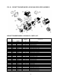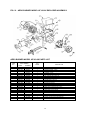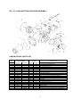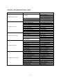
1
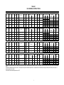
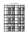
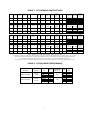
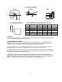
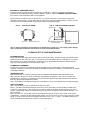
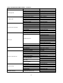
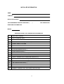
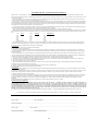
INSTALLATION, OPERATING and SERVICE MANUAL THE INSTALLATION OF THE UNIT SHALL BE IN ACCORDANCE WITH THE REGULATIONS OF THE AUTHORITIES HAVING JURISDICTION. OIL-FIRED HI-BOY – HEAVY DUTY FURNACES MODELS: NH3 and LFR HEAD OFFICE MARKETING / PRODUCTION Newmac Mfg. Inc. 208 LANCASTER CRESCENT P.O. BOX 9, DEBERT NOVA SCOTIA, BOM 1G0 PHONE: 902-662-3840 FAX: 902-662-2581 WAREHOUSE Newmac Mfg. Inc. 430 SPRINGBANK AVE., SOUTH WOODSTOCK, ONTARIO N4V 1B2 PHONE: 519-539-6147 FAX: 519-539-0048 EMAIL: [email protected] WEB SITE: newmacfurnaces.com NOTICE TO HOMEOWNER: READ AND SAVE THESE INSTRUCTIONS 156156 2210272 March 2010 Subject to change without notice Printed:__________ TABLE 1 NH3 GENERAL INSTRUCTIONS UPFLOW CONFIGURATION MODEL RIELLO BURNER B.T.U.H. OUTPUT NH3 – 122 40 F3 122,000 NH3 – 109 40 F3 109,000 NH3 – 95 40 F3 95,000 NH3 – 90 40 F3 89,000 MODEL BECKETT BURNER B.T.U.H. OUTPUT NH3 – 117 AFG60YHHS 117,000 NH3 – 101 AFG60YHHS 101,000 NH3 – 89 AFG60YHHS 89,000 NH3 – 77 AFG60YHHS 77,000 MODEL AERO BURNER B.T.U.H. OUTPUT NH3 – 100 HF-US-2X 101,000 NH3 – 88 HF-US-2X 89,000 NH3 – 78 HF-US-2X 77,000 MODEL CARLIN BURNER B.T.U.H. OUTPUT NH3 – 99 EZ-1 101,000 NH3 – 87 EZ-1 89,000 NH3 – 76 EZ-1 77,000 B.T.U.H. INPUT (USGPH) 144,976 (1.04) 128,248 (0.92) 111,520 (0.80) 103,156 (0.74) B.T.U.H. INPUT (USGPH) 139,400 (1.00) 118,490 (0.85) 104,550 (0.75) 90,610 (0.65) B.T.U.H. INPUT (USGPH) 118,490 (0.85) 104,550 (0.75) 90,610 (0.65) B.T.U.H. INPUT (USGPH) 118,490 (0.85) 104,550 (0.75) 90,610 (0.65) AFUE % 81.1 81.5 82.2 82.7 AFUE % 81.0 81.7 82.7 82.5 AFUE % 81.7 82.7 82.5 AFUE % 81.7 82.7 82.5 NOZZLE Delavan 0.85 X 60° B Monarch 0.85 X 60° R Delavan 0.75 X 60° B Monarch 0.75 X 60° R Delavan 0.65 X 60° B Monarch 0.65 X 60° R Delavan 0.60 X 60° B Monarch 0.60 X 60° R NOZZLE Delavan 1.00 X 70° A Monarch 1.00 X 70° NS Delavan 0.85 X 70° A Monarch 0.85 X 70° NS Delavan 0.75 X 70° A Monarch 0.75 X 70° NS Delavan 0.65 X 70° A Monarch 0.65 X 70° NS NOZZLE Delavan 0.85 X 70° A Monarch 0.85 X 70° NS Delavan 0.75 X 70° A Monarch 0.75 X 70° NS Delavan 0.65 X 70° A Monarch 0.65 X 70° NS NOZZLE Delavan 0.85 X 70° A Monarch 0.85 X 70° NS Delavan 0.75 X 70° A Monarch 0.75 X 70° NS Delavan 0.65 X 70° A Monarch 0.65 X 70° NS PUMP p.s.i. INSERTION inches 150 BURNER AIR SETTING CHIMNEY FLUE PRESSURE (in w.c.) GROSS STACK °F FILTER SIZE (QTY) TURB SHUTTER 4 5/8” 3 4.0 -0.02 500 16” X 24” (2) 150 4 5/8” 3 3.1 -0.02 460 16” X 24” (2) 150 4 5/8” 2 2.7 -0.02 425 16” x 24” (2) 150 4 5/8’ 1.5 2.5 -0.02 400 16” X 24” (2) CHIMNEY FLUE PRESSURE (in w.c.) GROSS STACK °F FILTER SIZE (QTY) PUMP p.s.i. INSERTION inches 100 BURNER AIR SETTING SHUTTER AIR BAND 5” 10 1 -0.02 515 16” X 24” (2) 100 5” 8 0 -0.02 475 16” X 24” (2) 100 5” 6 0 -0.02 450 16” X 24” (2) 100 5” 5 0 -0.02 425 16” X 24” (2) PUMP p.s.i. INSERTION inches CHIMNEY FLUE PRESSURE (in w.c.) GROSS STACK °F FILTER SIZE (QTY) 100 5” 7/16” -0.02 450 16” X 24” (2) 100 5” 5/8” -0.02 425 16” X 24” (2) 100 5” 7/8” -0.02 400 16” X 24” (2) GROSS STACK °F FILTER SIZE (QTY) BURNER AIR SETTING AIR BAND BURNER AIR SETTING CHIMNEY PUMP INSERTION FLUE POSITIONING p.s.i. inches AIR BAND PRESSURE BAR (in w.c.) DIRECT DRIVE SPEED TAP 12” 10” 9” BLOWER BLOWER BLOWER MED-HI MED-HI MED-HI MED-HI MED-HI MED-HI MED MED-LO MED-HI MED MED-LO MED-HI MED-LO MED-LO MED-LO MED MED-LO MED-HI MED-LO LO MED-LO MED LO MED-LO DIRECT DRIVE SPEED TAP 12” 10” 9” BLOWER BLOWER BLOWER MED-HI MED-HI MED MED MED MED MED-LO MED-LO MED-LO MED-HI MED-LO MED-LO MED-LO MED-LO LO LO MED-HI MED-HI MED-LO MED-LO MED-LO MED-LO LO LO DIRECT DRIVE SPEED TAP 12” 10” 9” BLOWER BLOWER BLOWER MED MED MED MED MED-LO MED-LO MED-LO MED-LO MED-LO MED-LO LO LO MED-LO MED-LO MED-LO MED-LO LO LO DIRECT DRIVE SPEED TAP 100 5” 0.85-1.00 GPH 0.65 -0.02 450 16” X 24” (2) 100 5” 0.75 GPH 0.60 -0.02 415 16” X 24” (2) 100 5” 0.60-0.65 GPH 0.50 -0.02 380 16” X 24” (2) 12” 10” 9” BLOWER BLOWER BLOWER MED MED MED MED MED-LO MED-LO MED-LO MED-LO MED-LO MED-LO LO LO MED-LO MED-LO MED-LO MED-LO LO LO PULLEY COMBINATION TURNS OPEN EXTERNAL STATIC PRESSURE (in w.c.) 3-1/4” X 6” 3-1/4” X 5” 3-1/4” X 6” 3-1/4” X 5” 3-1/4” X 6” 3-1/4” X 5” 1 – 1/2 1 2-1/2 2 3 2-1/2 0.20 0.50 0.20 0.50 0.20 0.50 PULLEY COMBINATION TURNS OPEN EXTERNAL STATIC PRESSURE (in w.c.) 3-1/4” X 6” 3-1/4” X 5” 3-1/4” X 6” 3-1/4” X 5” 3-1/4” X 6” 3-1/4 X 5” 3 2-1/2 3 2-1/2 3 2-1/2 0.20 0.50 0.20 0.50 0.20 0.50 BELT DRIVE BELT DRIVE BELT DRIVE PULLEY COMBINATION TURNS OPEN 3-1/4” X 6” 3-1/4” X 5” 3-1/4” X 6” 3-1/4” X 5” 3-1/4” X 6” 3-1/4” X 5” 3 2-1/2 3 2-1/2 3 2-1/2 BELT DRIVE PULLEY COMBINATION TURNS OPEN 3-1/4” X 6” 3-1/4” X 5” 3-1/4” X 6” 3-1/4” X 5” 3-1/4” X 6” 3-1/4” X 5” 3 2-1/2 3 2-1/2 3 2-1/2 EXTERNAL STATIC PRESSURE (in w.c.) 0.20 0.50 0.20 0.50 0.20 0.50 EXTERNAL STATIC PRESSURE (in w.c.) 0.20 0.50 0.20 0.50 0.20 0.50 Use burner air settings as a guide only. Set burner air to give a trace of smoke. Re-adjust burner air to reduce CO2 by 1 to 1.5 percent. Take measurements with the burner cover & air ducts installed (if any). The maximum allowable temperature rise is 85°F. Select speed to suit specific installation requirements. Air temperature can be lowered by increasing the blower speed; lowering the firing rate; or increasing supply & return outlets. The minimum recommended temperature rise is 65°F. 1 TABLE 2 – NH3 BLOWER PERFORMANCE DIRECT DRIVE BLOWER DELHI GT 12-7 DD DELHI GT 12-7 DD DIRECT DRIVE BLOWER DELHI G10-8 DD DELHI G10-8 DD DIRECT DRIVE BLOWER BLOWER SPEED TAP MOTOR 3/4 HP 5 SPD 3/4 HP 5 SPD HIGH MED-HI MEDIUM MED-LO LO 1,045 850 750 710 680 1/2 HP 4 SPD 1/3 HP 4 SPD DELHI G9 DD or TORIN DC 916-916-5 1/3 HP 4 SPD 0.50 1,610 1,200 1,090 860 760 4.00 3.00 2.50 2.00 1.75 DIRECT DRIVE BLOWER BLOWER MOTOR SPEED TAP RPM LAU DD 12-8AT 3/4 HP 5 SPD HIGH MED-HI MEDIUM MED-LO LO 1,010 790 720 670 510 STATIC A/C PRESSUR CFM TONS E (in w.c.) 0.50 1,775 1,250 980 830 740 HIGH 1,040 1,735 HIGH 980 760 1,260 MED-HI 700 MEDIUM 650 MEDIUM 610 MED-LO 585 915 MED-LO 540 910 LO 540 800 LO 500 810 SPEED TAP RPM HIGH MED-HI 1,115 1,090 MED-LO LO 1,050 1,000 HIGH 1,095 RPM HIGH MED-HI 1,055 1,010 MED-LO LO 920 845 HIGH 1,015 MED-HI 925 MED-LO 795 LO 670 BLOWER SPEED TAP MOTOR DELHI G9 DD or TORIN DC 916-916-5 STATIC A/C PRESSUR CFM TONS E (in w.c.) MED-HI BLOWER SPEED TAP MOTOR 1/2 HP 4 SPD RPM HIGH MED-HI MED-LO LO HIGH MED-HI MED-LO LO RPM 1,095 1,045 980 920 1,065 980 850 750 0.20 LAU DD 12-8AT 1,115 STATIC A/C PRESSUR CFM TONS E (in w.c.) 0.50 1,420 1,280 3.50 3.00 1,115 900 2.75 2.25 3/4 HP 5 SPD DIRECT DRIVE BLOWER BLOWER MOTOR DELHI G9 DD 1/2 HP 4 SPD 1,540 0.20 1,390 DELHI G9 DD 1,180 1/2 HP 4 SPD 940 STATIC A/C PRESSUR CFM TONS E (in w.c.) 0.50 0.20 1,250 1,165 960 835 1,415 1,255 1,070 875 3.00 2.75 2.25 2.00 BELT DRIVE BLOWER BLOWER MOTOR DELHI G9 BD 1/2 HP c/w or 3-1/4” VS TORIN BC 916-916-5 Pulley c/w 6” Pulley DELHI G9 BD 1/2 HP c/w or 3-1/4” VS TORIN BC 916-916-5 Pulley c/w 6” Pulley 2 MED-HI 1,050 MED-LO 985 LO 890 PULLEY TURNS OPEN RPM 1 1-1/2 2 3 1-1/2 2 2-1/2 3 1,017 970 985 915 845 820 795 770 4.25 3.00 2.25 2.00 1.75 1,975 1,340 0.20 1,040 STATIC A/C PRESSUR CFM TONS E (in w.c.) 0.50 1,300 1,230 3.00 3.00 1,125 1,065 2.75 2.50 1,495 0.20 1,380 1,230 1,140 STATIC A/C PRESSUR CFM TONS E (in w.c.) 0.50 0.20 1,200 1,050 1,000 840 1,100 1,090 985 970 3.00 2.50 2.50 2.00 TABLE 3 - LFR GENERAL INSTRUCTIONS CHIMNEY EXTERNAL GROSS DIRECT DRIVE TAP FLUE STATIC STACK FILTER PRESSURE o SHUTTER 10" BLOWER 9" BLOWER PRESSURE F (in. w.c.) (in. w.c.) MED-LO MED-HI 0.20 3.4 -0.02 380 20" x 25" MED-HI 0.50 LO MED-LO 0.20 -0.02 2.7 350 20" x 25" MED-LO HI 0.50 LO MED-HI 0.50 RIELLO BURNER B.T.U.H. OUTPUT B.T.U.H. INPUT (USGPH) AFUE % LFR-88 40 F3 88,000 101,762(0.73) 81.7 Delavan 0.60 60A 150 2" 1.5 LFR-75 40 F3 75,000 85,034(0.61) 81.2 Delavan 0.50 80B 150 2" 0.5 MODEL BECKETT BURNER B.T.U.H. OUTPUT B.T.U.H. INPUT (USGPH) AFUE % NOZZLE LFR-89V AFG70MM 89,000 101,762(0.73) 82.2 Hago 0.55 45B 180 2-3/8" 6 0 LFR-80V AFG70MM 81,000 93,398(0.61) 82.0 Hago 0.50 45B 180 2-3/8" 7.5* 0 RIELLO BURNER B.T.U.H. OUTPUT B.T.U.H. INPUT (USGPH) LFR-86V BF3 86,000 100,386(0.72) 82.3 Delavan 0.60 60A 145 2" 1.5 LFR-73V BF3 73,000 83,640(0.60) 81.9 Delavan 0.50 80B 145 2" 1 MODEL CARLIN BURNER B.T.U.H. OUTPUT B.T.U.H. INPUT (USGPH) AFUE % NOZZLE LFR-87 EZ PRO 87,000 101,762(0.73) 81.7 Delavan 0.60 60A 150 1-1/2" 0.60/0.65 0.75 LFR-72 EZ PRO 73,000 85,034(0.61) Delavan 0.50 60A 150 1-1/2" 0.5 0.60 MODEL NOZZLE PUMP INSERTION p.s.i.. inches BURNER AIR BAND BURNER AIR PUMP INSERTION p.s.i.. Inches SHUTTER BAND CHIMNEY GROSS EXTERNAL DIRECT DRIVE TAP FLUE STACK STATIC FILTER o PRESSURE F 10" BLOWER 9" BLOWER PRESSURE (in. w.c.) (in. w.c.) MED-LO MED-HI 0.20 -0.02 400 20" x 25" MED-HI 0.50 MED-LO MED-HI 0.20 -0.02 360 20" x 25" MED-LO HI 0.50 * USE LOW FIRING RATE BAFFLE MODEL AFUE % 80.7 NOZZLE PUMP INSERTION p.s.i.. inches CHIMNEY GROSS EXTERNAL DIRECT DRIVE TAP FLUE STACK STATIC FILTER o F SHUTTER PRESSURE 10" BLOWER 9" BLOWER PRESSURE (in. w.c.) (in. w.c.) MED-LO MED-HI 0.20 4.4 -0.02 380 20" x 25" MED-HI 0.50 LO MED-LO 0.20 -0.02 3.8 350 20" x 25" MED-LO HI 0.50 BURNER AIR TURB BURNER AIR PUMP INSERTION p.s.i.. inches POS BAR BAND CHIMNEY EXTERNAL GROSS DIRECT DRIVE TAP FLUE STATIC STACK FILTER PRESSURE o 10" BLOWER 9" BLOWER PRESSURE F (in. w.c.) (in. w.c.) MED-LO MED-HI 0.20 -0.02 390 20" x 25" MED-HI 0.50 -0.02 360 20" x 25" LO MED-LO 0.20 Models marked -V can be used with the Newmac SVS sealed vent system. Use burner air settings as a guide only. Set burner air to give a trace of smoke. Re-adjust burner air to reduce CO2 by 1 to 1.5 percent. Take measurements with the burner cover & air ducts installed (if any). The minimum recommended temperature rise is 65 oF. The maximum allowable temperature rise is 85oF. Select speed to suit specific installation requirements. Air temperature can be lowered by increasing the blower speed, lowering the firing rate, or increasing supply & return outlets. TABLE 4 - LFR BLOWER PERFORMANCE DIRECT DRIVE BLOWER BLOWER MOTOR DELHI GT 10DD 1/3 HP 4 SPD DELHI GT 10DD 1/3 HP 4 SPD SPEED TAP RPM HIGH MED-HI MED-LO LO HIGH MED-HI MED-LO LO 1,080 1.030 960 910 1,050 850 740 670 3 STATIC PRESSURE (IN. W.C.) 0.50 0.20 CFM 1,200 1,000 875 750 1,350 1,200 1,000 800 A/C TONS 3.00 2.50 2.00 1.75 FURNACE LOCATION IMPORTANT Please read this entire manual and all labels before installing the furnace. UNPACKING AND INSPECTION It is the responsibility of the consignee of the unit to examine the packages for damage and, if found, to note the same on the Carrier’s Bill of Lading. The NH3 furnace is shipped in one package complete with oil burner, draft regulator, filter racks, air filters, A/C Control Center (optional) and instruction manual. The LFR is shipped in two packages. Caution: Remove shipping retaining bracket from blower before start-up. HEAT LOSS Before installation, verify the furnace output capacity meets the building heat loss requirements. A detailed heat loss analysis is recommended. INSTALLATION REGULATIONS This unit should be installed in accordance with the regulations of the authority having jurisdiction. In Canada the installation must conform to CSA Standard B139, "The Installation Code for Oil Burning Equipment." In the United States, the National Fire Protection Association Standard NFPA 31 should be followed. Check with provincial, state, or local codes concerning clearances, venting system requirements and other regulations governing installation. Some codes may vary from the requirements set forth in this manual. FOUNDATION To ensure the furnace is on a level foundation and above any possible dampness, a cement pad is recommended. CLEARANCES The minimum clearances to combustible materials are as follows: 6" Side Rear Top Front* Flue Pipe Floor NH-3 6” 6” 1” 24” 9” Combustible LFR 1” 2” 1” 16” 9” Combustible * Measured from the panel on which the burner is installed. Allow sufficient room for servicing. FOR YOUR SAFETY: Do not store or use gasoline or flammable vapors and liquids in the vicinity of this or any other appliance. VENTING PRODUCTS OF COMBUSTION CHIMNEYS A negative overfire pressure should be maintained. Locate the furnace as close to the chimney or flue as possible. The maximum draft is obtained by keeping elbows and pipe length to a minimum. Install the flue pipe with a gradual rise of at least 1/4" per foot from the furnace to the flue. Do not extend the flue pipe beyond the inside wall of the chimney. Refer to Table 11(a) and Table 11(b) for proper chimney flue sizing and Fig. 23 for optimizing chimney draft. The owner shall provide a chimney constructed to comply with the following specifications: (a) The chimney must be absolutely smoke tight throughout its entire length, and must extend at least three feet (3') above a flat roof or two feet above the ridges of peak roofs. 4 (b) If built of a single thickness of brick or of cement blocks, it shall be lined throughout its entire length with fire clay lining, having not less than three-fourths inch (3/4") thickness. Flue lining is to be laid in mortar and made airtight. If the chimney is of the prefabricated type, it must be an approved class "A" chimney or type "L" Vent for interior. (c) The furnace flue must have no other openings for attaching any fireplace, stove, range, gas or ventilating connection unless the equipment is appropriately certified. (d) If it is necessary to offset the flue, it must be done in such a manner as not to reduce the gross crosssectional area or create a ledge or obstruction, where loose material may lodge. (e) Flue pipe connections must be secured with metal screws. CAUTION: Oil-fired appliances shall be connected to flues or vents having sufficient draft at all times to ensure safe and proper operation of the appliance. BAROMETRIC DRAFT REGULATOR A Listed/Certified draft regulator must be installed between the appliance and the chimney, within easy reach for adjustment and free from obstruction. Use larger or multiple draft regulators for chimneys with strong draft. Follow the manufacturer's instructions located with the draft regulator for proper installation. BLOCKED VENT SWITCH The WMO-1 blocked vent control is required on Newmac oil-fired and combination furnaces or boilers installed in Canada. The WMO-1 switch must be installed on the chimney vent pipe for Newmac oil fired furnaces and boilers; and installed on the burner plate for Newmac combination wood/oil or coal/oil fired furnaces. Do not use the WMO-1 Blocked Vent Switch with the Newmac Sealed Vent System (SVS). Refer to the Newmac and Field Controls Instructions enclosed in the WMO-1 package. Wiring WMO-1 Primary Control WMO-1 T T F F Limit N Cad Cell Connect WMO-1 at appliance junction box (except CL series) Motor CL series combination furnaces: Connect WMO-1 at the burner control junction box Ignition Burner POWER VENTING The NH3 furnace is certified for use with Field Controls SWGII-5 Through the Wall Venter. This vent kit p/n 2040023 contains the NM-61 electronically activated post purge control. Secondary Safety Switch WMO-1 is optional. Consult installation codes for requirements and approvals governing power venters and draft inducers. Follow the instructions supplied with the vent system for proper installation. LFR furnace models with the suffix –V are certified for use with the NEWMAC SVS sealed direct vent system. 5 PROPER DUCT SIZING Locate the furnace as close as possible to the center of the heat distribution system and make sure the top is level. Refer to TABLES 6 and 7, DUCT SIZING FOR HEATING and COOLING in this manual. AIR CONDITIONING This appliance is designed to accommodate air conditioning equipment. A/C ready models incorporate a fan center transformer / relay. Live motor leads must be isolated on direct drive motors using a two speed fan & limit control or a suitable fan center control. HUMIDIFIER If a humidifier is installed, ensure water cannot drip on the heat exchanger. This will damage the furnace and void the warranty. ELECTRICAL CONNECTIONS The NH3-4 furnace is rated at 120V, 60Hz, 1-Phase, 20 Amp fuse. The LFR and NH3 furnaces are rated at 120V, 60Hz, 1-Phase, 15 Amp fuse See the furnace marking label. Follow the National Electrical Code as well as provincial, state, and local regulations. Figs. 13, 14 and 15 show standard wiring schematics. FUEL SYSTEMS Fuel not heavier than No. 2 fuel oil must be used. The oil supply tank must be of a listed or certified type acceptable to the regulatory authority having jurisdiction. Install the oil tank or tanks according to local codes and regulations. The tank should be kept at least 1/4 full. If a two-pipe system is used, suction and return lines should be of the same diameter and extend to the same depth in the tank. An emergency oil shut-off valve should be installed as required by local ordinance. This can be manual, electric solenoid, or vacuum operated. An oil safety valve that cuts the fuel supply unless a vacuum is created by the pump is recommended. Any leaks in the system will prevent oil from flowing. Suntec PRV or Webster OSV valves are recommended. Loop copper lines connected directly to the oil pump to reduce vibration. Use separate oil line for each individual appliance to prevent “loss of prime” problems. THERMOSTAT Locate the thermostat on an interior wall free from drafts approximately 5 feet above floor level. The operation of the burner is normally controlled by the room thermostat, which may be set for the temperature desired, typically 70°F. if a higher or lower temperature is desired, the indicator should be set to the proper point on the scale. THERMOSTAT HEAT ANTICIPATOR To prevent short cycling, the heat anticipator should be set as recommended in the specifications for the burner primary control. This is typically set at 0.1 or 0.2 amps as indicated in Figure 1. This adjustment changes the thermostat’s response time to prevent the room temperature from over-running the thermostat setting. FIG. 1 - Heat Anticipator WARNING: The heat anticipator will BURN OUT if 25 volts are applied directly to the thermostat by shorting out the primary control during testing or incorrect wiring. If this happens the thermostat warranty is void. 6 FAN & LIMIT CONTROL This thermally operated control has a probe to sense air temperature inside the appliance adjacent to the heat exchanger. Fig. 3 shows the main parts of a Honeywell L4064 Fan & Limit Control. Refer to Fig. 4 for its settings. For controls equipped with the Manual-Auto switch button constant fan operation can be achieved by pushing it to the MAN position. High Limit Setting: See Figs. 2, 3 and 4. This setting is factory set – DO NOT CHANGE The high limit setting limits burner operation. When the air temperature inside the appliance reaches the set high limit value, overheating of the furnace is prevented by cutting power to the burner. When the temperature falls below the set high limit the burner power is restored. Fan-On Setting: See Figs. 2, 3 and 4. This setting starts the air circulation blower when the burner has warmed the furnace to the fan-on temperature Fan-Off Setting: See Figs. 2, 3 and 4. This setting keeps the air circulation blower running until the temperature of the heat exchanger drops to the fan-off temperature. This ensures the blower adequately cools the heat exchanger before shutting off and keeps cool air from being circulated through the ductwork. Fan differential (difference between the Fan On & Fan Off settings) should be at least 15oF (8 oC). FIG. 2. TWO SPEED FAN & LIMIT CONTRL-L6064A FIG. 3. SINGLE SPEED FAN & LIMIT - L4064B FIG. 4. FAN AND LIMIT SETTINGS NH3 LFR FAN ON FAN OFF 125 90 110 90 * Do not change high limit setting LIMIT* 200 200 COMBUSTION AND VENTILATION AIR FOR CHIMNEYS & POWER VENTERS Free air for combustion and ventilation must be permanently provided to the furnace room. Combustion air refers to the total air requirements of the fuel-burning appliance. This includes air for the combustion process and air to provide chimney draft (dilution air). Ventilation air provides free circulation of air in the room where the appliance is located to keep ambient temperatures within safe limits under normal conditions. 7 Furnaces installed in tight houses, in houses which have air-handling devices with unbalanced airflows, or in enclosed spaces are very likely to have homeowners complain of smoke, fumes, burner lockouts, and excessive fuel consumption. This is more prevalent in post 1985 construction due to the tighter building construction as prescribed by the latest building codes. Regulations are relatively specific on the minimum allowable quantities of ventilation and combustion air required once the space category is determined. However, every house is subject to different internal and external conditions and regulations vary among localities. With this in mind, Newmac recommends provision for combustion and ventilation air as specified in Table 5. Table 5 is based on relevant commonly available codes and regulations. Values indicated in Table 5 are based on the maximum input rating for this single appliance. However, in making combustion and ventilation analysis the aggregate input rating of all appliances in the space must be considered. The installation of additional oil-fired appliances may require more combustion and ventilation air. When sizing combustion and ventilation air ducts, allowance must also be made for the blocking effect of louvers, grilles and screens. If the design and free area is unknown, wood louvers generally have 20-25% free area and metal louvers or grilles have 60-75% free area. Screens should not be less than 1/4 inch mesh. TABLE 5. COMBUSTION & VENTILATION AIR SIZING FLOORAREA APPLIANCE (Square feet) SPACE Vertical Ducts &Direct Opening Sizes CATEGORY Free Area 2 NH3 more than 725 Unconfined 725 or less LFR Confined more than 725 Unconfined 725 or less Confined L X W (QTY) Dia. (QTY) Horizontal Duct Sizes (in.) Free Area L X W (QTY) Dia. (QTY) Total (in.2) Total (in. ) (in. X in.) (in.) (in. Xin.) (in.) 30 4 x 8 (1) 6 (1) 30 4 x 8 (1) 6 (1) 72 4 x 9 (2) 7 (2) 145 4 x 18 (2) 10 (2) 21 4 x 6 (1) 5 (1) 21 4 x 6 (1) 5 (1) 52 4 x 7 (2) 6 (2) 105 6 x 9 (2) 8 (2) Free area of ducts assumes air is conveyed fromoutside The following should be kept in mind when using Table 5: All applicable codes and regulations must be followed. Free duct area is for ducts and opening to outdoors. Unconfined free area values are based on 1 sq. in per 5,000 Btu/hr of the maximum input rating. Confined free area of vertical ducts is based on 1 sq. in per 4,000 Btu/hr of the maximum input rating. Confined free area of horizontal ducts is based on 1 sq. in per 2,000 Btu/hr of the maximum input rating. Two openings of equal size are required for confined spaces. Maximum length of run for ducts is 50 ft. Duct size allowances must be made for longer runs. Ducts should be designed or insulated to prevent condensation. If insulating, a minimum insulation value of R-3 is required. In the case where one opening or duct is specified and combustion and ventilation air is still inadequate, a second duct may be required. Locate one high and the other low for air circulation. It is particularly important to duct the cold air as close to the appliance as possible. A means of closing the air openings when the appliance is not operating may be required. Except for an SVS sealed vent installation, outside air ducts should not be connected either to the burner or to the appliance. Guidelines to determine the need for additional combustion and ventilation air may not be adequate for every situation. If in doubt, it is advisable to err on the safe side and provide additional air. Fig. 5 shows a typical appliance installation. In this case there is a furnace and a water heater in an enclosed space--both require ventilation and combustion air which is delivered by the top and bottom air ducts. As long as adequate combustion and ventilation air is supplied, the confined appliance room with ducted air offers several advantages: 8 The incoming cold air is confined to the furnace room. Therefore, the residence occupants are less susceptible to drafts. Cool outdoor air will be tempered by the ambient temperature of the furnace room before it enters habitable spaces. Noise levels may be reduced. The furnace will be less susceptible to combustion spillage and back-drafting in low draft situations reducing odor and smoke. Moderate amounts of smoke and fumes will be contained and expelled safely outdoors. Incomplete combustion of any carbon-based fuel may produce deadly carbon monoxide. Ventilation may dilute any carbon monoxide produced under abnormal operating conditions. Adequate air for combustion will help maintain the proper air-fuel ratio. Appliances, which are burning fuel rich, will produce soot and burn excessive fuel. A 1/8 inch thick deposit of soot on the surface of the heat exchanger is equivalent to 1 inch of fiberglass insulation. Modern efficient oil burning appliances tend to be physically smaller than are their predecessors are. As a result, hot surfaces such as those on flue connectors are not as high off the ground or floor as they used to be. A separate furnace room with a “child proof” door is an important safety precaution. FIG. 5. APPLIANCE LOCATED IN CONFINED SPACE WITH ALL AIR FROM OUTDOORS 9 OIL BURNER INSTRUCTIONS BURNER CARE This burner is fully automatic in operation. All adjustments should be made by a qualified technician. Keep the burner free from excess dirt and moisture. Oil leaks should be tended to immediately. If the burner motor has oiler openings, the motor should be given a few drops of SAE 20 non-detergent oil at least two or three times a year. No other parts require lubrication. CAUTION: Do not use gasoline, crankcase or any oil containing gasoline. Do not tamper with the unit or controls--call the serviceman. Do not attempt to start the burner when excess oil has accumulated, when the unit is full of vapor, or when the combustion chamber is very hot. Do not start the burner unless the cleanout doors are secured in place. Do not burn garbage or paper in the heating system. Never leave combustible materials such as paper or rags near the unit. OIL BURNER INSTALLATION Install the oil nozzle in the burner firing assembly, and check the adjustments. See Fig. 6 and Table 6 for the correct electrode settings. These settings are critical for proper burner operation. Some burner manufacturers have a gauge available for setting the electrodes. Most burners with adjustable heads have preset stops to ensure the distance from the nozzle face to the face of the retention head (“Z” dimension) is correct. Set or check the air tube insertion depth according to Fig. 7 and Table 6. This is the distance from the face of the burner-mounting flange to the face of the retention head. Mount the oil burner on the lugs of the burner plate carefully centering it in the combustion chamber port. Use TABLES 1 (NH3) or 3 (LFR), GENERAL INSTRUCTIONS for preliminary air settings for the burner. BURNER SET-UP AND ADJUSTMENT The installer must use a suitable draft gauge, smoke tester, carbon dioxide tester, 0-750°F stack thermometer, 0-200 psi oil pressure gauge, 0-30 in. Hg. vacuum gauge, and 0-220°F thermometer to properly set-up the burner. 1. Turn on supply power and set the thermostat above room temperature. 2. Open all oil lines and valves. 3. Make sure the oil pump by-pass plug is correctly installed for a one or two pipe system. Bleed any air from the oil pump (refer to pump manufacture's instructions). 4. Adjust the burner air until a #1 smoke or less is reached using a smoke tester. If a smoke tester is unavailable, slowly close the air band until the fire becomes smoky. Slowly increase the air until a small amount of smoke is observed at the flame tips. If the burner fails to start, check (a) oil supply, (b) ignition electrodes and transformer, (c) cad cell. If the burner goes off on safety, do not push the reset button on the primary control for at least 10 minutes. Do not push the reset button more than once before correcting the cause. If the burner still does not start, press the reset on the burner motor. 5. Using a suitable draft meter, adjust the barometric draft regulator to measure the specified flue pressure. This requires that a 5/16" diameter sampling hole be made between the flue collar and the draft regulator. EXTENDED SHUT DOWN PERIODS When the appliance is not to be used for an extended period of time, set the thermostat at its lowest value, turn off the main switch and close the oil burner supply valve. If the heating unit room is damp, protect the burner against dirt and moisture with a light cover. To resume operation, remove the cover and inspect the burner. Remove any dirt and debris gently to avoid the need to adjustment the air band. Open the supply valve and turn on the main switch. If the burner fails to operate, see the MAINTENANCE & SERVICE section of this manual. 10 ELECTRODE SETTINGS FIG 6A FIG 6B A FIG 6C B C Z FIG 7 BURNER INSERTION TABLE 6 DIMENSIONAL RELATIONSHIPS (Figs 6 & 7) Riello 40 or BF E A B C Z E - NH3 E - LFR 5/32” 13/64” 5/64” to 7/64” Refer to Turbulator Setting 4-5/8” 2” ` Beckett Std. Head 5/32” 7/16” 1/16” 1-1/8” (Fig 6A) 5” 2-3/8” Beckett Adj. Head 5/32” 7/16” 1/16” 1-3/4” (Fig 6C) 5” 2-3/8” Aero Carlin 1/8” 7/32” 1/8” 1-1/8” (Fig 6A) 5” 2” 1/8” to 5/32” 5/16” 1/16” Use Positioning Bar 5” 1-1/2” Use burner manufacturer’s gauge if supplied. OIL FILTER Use a 10 micron or better filter. We recommend an additional in-line filter. The oil filter should be cleaned or replaced at least once a year by the serviceman. OIL PUMP AND FUEL SYSTEM Make sure the by-pass plug is correctly located for a one or two pipe system. Failure to do so may damage the pump. Generally, for 3/8” copper tubing, the vertical lift should not exceed 8 feet and the horizontal run should be limited to 30 feet. Do not exceed 10 psi inlet line pressure. Single pipe systems are recommended for gravity feed or when the tank outlet is at a higher elevation than the pump inlet. Refer to Fig. 10. The inlet vacuum should be no more than 6" Hg. Two pipe systems are recommended for lift feed or when the pump inlet is at a higher elevation than the tank outlet. Install the return line termination higher than the supply intake as shown in Fig. 10. Generally, the inlet vacuum should be no more than 12" Hg. Correct piping is critical to long-term operation of the fuel system. Never use compression fittings. Minimize the resistance to flow due to excessive line lengths; high lift; and unnecessary fittings, kinks and bends. This will decrease the running vacuum and the risk of air separation. A “Tigerloop” fuel oil deaerator may improve the performance of poorly designed fuel oil delivery systems. 11 BURNER OIL PRESSURE CHECK Install the pressure gauge directly on the gauge or nozzle port. Adjust to the pressure specified by Newmac for the nozzle input rating. Refer to TABLE 1 (NH3) or 3 (LFR), GENERAL INSTRUCTIONS in this manual or the certification label on the appliance. Each oil burner should have its own suction line. A common return line can be used as long as the diameter is large enough. Check valves are not required on properly installed systems. Service on fuel units should not be attempted without a suitable vacuum and pressure gage. FIG. 8. TYPICAL OIL PUMP GAUGE PORT FIG. 9. RIELLO SLEEVE POSITION Setback 0-1/4" NOZZLE PORT Gasket INLET PORT Insertion to flange (TF) BLEED PORT INLET PORT Riello Burner End Cone Protector Part No. 2030016 RETURN & BY-PASS PORT Riello BF3 Riello 40F3 The oil piping information presented here is intended as a guide only. For piping system design data, consult the installation instructions from the pump manufacturer. FURNACE SET UP AND MAINTENANCE BLOWER MOTORS Motor manufacturers supply some motors that do not require oiling. Oil ports usually have plastic covers and are found on the motor end caps. If oil ports are not incorporated, oiling is not required. For motors with provision for re-oiling use SAE 20 non-detergent oil or oil specially formulated for electric motors. Use only a few small drops two or three times a year. COMBUSTION CHAMBER For the NH3, make sure the cerafelt combustion chamber was not damaged or mis-aligned during shipping. Inspect the combustion chamber periodically and replace if necessary. The LFR has no cerafelt combustion chamber. SMOKE BAFFLES Both the NH3 and the LFR furnaces have factory installed smoke baffles inside the radiator ducts. NH3 - Check to ensure they have not become dislodged during shipping. They can be checked and repositioned, if necessary, by reaching in through the breech pipe and pushing them down the tubes so their stop tabs are flush against the welds. LFR – The baffles are accessed through the front cleanout covers. No adjustment is normally necessary. AIR FILTER RACK NH3 - The air filter rack can be positioned on the left or right. NH3-4 - The filter racks shipped with the furnace mount on both sides. Knockouts are provided at the corners to cut the opening. The opening in the rack for sliding in the filters should face the front of the furnace, unless there is there is enough clearance at the rear to change the filters without damage — at least 24 inches. LFR – See FIG. 12. The air filter rack can be positioned on the left or right, rear or base of the blower compartment. The left and right openings are already cut; the one which is not in use is covered by a side panel. If a rear or base opening is required it should be cut (17-3/4” x 13-3/4”). An additional side cover can be obtained from Newmac to cover the unused side opening. 12 AIR FILTERS Air filters should be inspected monthly and changed as required. At least two changes are usually required during the heating season—more may be necessary if dusty conditions exist. Remove the filter gently to prevent dust spillage. Install filters of the same size and type. Check filter markings for correct orientation. BLOWER REMOVAL Disconnect power before removing or servicing the blower. Remove the burner and blower access panels on the front of the furnace. Remove the nut and bolt that fastens the blower locking plate to the fan partition and slide the blower locking plate out. The blower is mounted on slide rails which allow it to be pulled forward for servicing. The wiring harness has sufficient length so that it can be removed without disconnecting the motor leads. If the capacitor leads need to be removed, short the terminals with an insulated screwdriver before handling. BLOWER ADJUSTMENT o This unit is designed for a maximum temperature rise through the furnace of 85 F at a maximum external static pressure of 0.50 inches of water column. However, due to the wide range of static pressures in duct o systems, it is the responsibility of the installer to verify that the temperature rise does not exceed 85 F. To measure the actual temperature rise let the unit operate for at least five minutes. Insert a thermometer and note the temperature of the warm air supply at a point at least 24 inches upstream from the heat exchanger surface. Next measure the temperature at the return air grill and take the difference. Air temperature rise can be lowered by increasing the blower speed; lowering the firing rate; or increasing undersized supply and return air free area. The furnace will not operate properly and its life will be decreased if insufficient air quantity passes over the heat exchanger. Similarly, too much air during o heating mode resulting in a temperature rise of less than 65 F may cause heat exchanger degradation due to condensation. DIRECT DRIVE BLOWER The installer should select the best speed tap for the specific installation. Recommended speed taps for heating are given in TABLES 1 (NH3) AND 3 (LFR) GENERAL INSTRUCTIONS. The motor RPM will vary over a range of static pressures. The blower heating speed can be changed by moving the black wire harness lead to another speed tap on the terminal block located inside the blower compartment. Refer to TABLES 2 (NH3) and 4 (LFR), BLOWER PERFORMANCE for airflow data. A second speed for nonheating modes can be selected using the red wire harness lead. See FIG. 13 and 14 for WIRING SCHEMATICS. BELT DRIVE BLOWER – NH3 only The air delivery (CFM) and temperature can be varied by adjusting the motor pulley. Closing the pulley increases blower speed and decreases temperature rise. Opening the pulley decreases the blower speed and increases the temperature rise. A 6 inch diameter blower pulley is required for 0.20 inch w.c. static pressure. A 5 inch diameter pulley is used for 0.20 inch w.c. static pressure. Correct belt tension allows a 1 inch deflection midway between the pulleys. Too much tension will overload the motor—too little tension will cause slippage. Pulley combinations vary according to the fuel input and duct static pressure. Recommended pulley combinations for heating mode are given in TABLE 1 (NH3), GENERAL INSTRUCTIONS. Refer to TABLE 2 (NH3), BLOWER PERFORMANCE for air flow data. An optional two-speed motor is available. The low speed can be used in non-heating mode. If the unit is not factory wired for a two-speed motor, connect the red wire of the blower wire harness to the correct motor lead. See FIG. 15 for STANDARD WIRING SCHEMATIC - BELT DRIVE and follow the motor manufacturer’s instructions. Make sure replacement and retrofit belt drive motors meet or exceed the OEM motor specifications. Two speed belt drive motors are available from Newmac. 13 MAINTENANCE & SERVICE Maintenance and servicing must be done by a qualified burner technician or shortened furnace life and poor efficiency may result. Under Tests and Observations and Requirements in CSA B139, the installer is required to perform tests to ensure proper and safe operating conditions. Newmac requires the installer to fill out the INSTALLER INFORMATION sheet found in this manual. CLEANING The heat exchanger should be inspected on an annual basis. If cleaning is required, remove the cleanout cover. Use a wire brush or cleaning tool (available from Newmac) to loosen scale and soot and a vacuum cleaner to remove it from the furnace. Replace gaskets if necessary before replacing the cleanout cover. A layer of soot on the heat exchanger surfaces and firetube walls will reduce heat transfer and can increase fuel consumption significantly. A 1/32” layer of soot acts as an insulator and can result in a 3% increase in the amount of oil burned. A 1/16” layer may result in an average fuel loss of 8%. When removing the burner, cleanout or cover panels take care not to damage gaskets. NH3 FURNACE - take care not to break the combustion chamber. Removal of the combustion chamber plate assembly allows a more thorough inspection and cleaning. Replace all parts properly before starting the appliance. WARRANTY The following information is required to process warranty claims: owner’s name and address; furnace serial number, model number, installation date; and installer’s name, address and phone number. A “Returned Goods Number” must be issued by Newmac prior to acceptance of returned goods. Refer to the LIMITED LIFETIME WARRANTY for terms and conditions. 14 IMPORTANT HOMEOWNER INSTRUCTIONS 1. AN EMERGENCY POWER SWITCH IS REQUIRED TO BE INSTALLED IN A CONVENIENT LOCATION AT A SAFE DISTANCE FROM THE BURNER. THIS SWITCH INTERRUPTS THE ELECTRICAL SUPPLY CIRCUIT TO THE APPLIANCE. MAKE SURE YOU ARE AWARE OF ITS LOCATION AND THE OFF POSITION IS CLEARLY MARKED. 2. KEEP THE SPACE CLEAR AROUND THE APPLIANCE WITHIN THE SPECIFIED CLEARANCES TO COMBUSTIBLES. 3. ENSURE THE SUPPLY OF COMBUSTION AIR TO THE APPLIANCE IS NOT OBSTRUCTED OR CUT-OFF. 4. MAINTAIN PROPER VENTILATION OF THE APPLIANCE AREA. 5. MAINTAIN FREE AIR FLOW THROUGH THE RETURN AIR REGISTERS. * 6. CONTACT SERVICE PERSONNEL BEFORE REMODELLING. 7. CONTACT SERVICE PERSONNEL FOR ANNUAL SERVICE AND MAINTENANCE. 8. CONTACT SERVICE PERSONNEL FOR AIR FILTER REPLACEMENT. * 9. CONTACT SERVICE PERSONNEL BEFORE AND AFTER EXTENDED PERIODS OF APPLIANCE INOPERATION. 10. THE BURNER IS FULLY AUTOMATIC IN OPERATION. ALL ADJUSTMENTS SHOULD BE MADE BY A QUALIFIED TECHNICIAN. DO NOT PUSH THE RESET BUTTON MORE THAN ONCE. CAUTION : DO NOT ATTEMPT TO START THE BURNER WHEN EXCESS OIL HAS ACCUMULATED, WHEN THE APPLIANCE IS FULL OF VAPOUR, OR WHEN THE COMBUSTION CHAMBER IS VERY HOT. 11. CAUTION : DO NOT TAMPER WITH THE APPLIANCE OR CONTROLS—CALL YOUR SERVICE PERSONNEL. 12. DO NOT USE GASOLINE, CRANKCASE OIL, OR ANY OIL CONTAINING GASOLINE 13. ALWAYS KEEP THE OIL SUPPLY VALVE SHUT OFF IF THE BURNER IS SHUT DOWN FOR AN EXTENDED PERIOD OF TIME. 14. DO NOT START THE BURNER UNLESS THE BLOWER ACCESS DOOR IS SECURED IN PLACE. 15. NEVER BURN GARBAGE OR PAPER IN THE HEATING SYSTEM, AND NEVER LEAVE PAPER OR RAGS AROUND THE APPLIANCE. * FURNACES ONLY 15 FIG. 10. TYPICAL OIL TANK PIPING INSTALLATIONS 16 FIG. 11. DIMENSIONS & CONTROL LOCATION – NH3 17 FIG. 12. LFR SET UP 18 FIG. 13. STANDARD WIRING SCHEMATIC - DIRECT DRIVE 19 FIG. 14. STANDARD WIRING SCHEMATIC - A/C READY DIRECT DRIVE 20 FIG. 15. STANDARD WIRING SCHEMATIC - BELT DRIVE 21 TABLE 6. DUCT SIZING FOR HEATING WITHOUT A/C COIL 800 CFM 900 CFM 1100 CFM 1400 CFM 1600 CFM 1800 CFM 2000 CFM 1 - 35" X 10" or 20" round or 2 - 22" X 8" 1 - 35" X 12" or 2 - 22" X 10" 1 - 35" X 14" or 2 - 22" X 12" 3 1/2 X 14" 170 CFM 165,000 to 170,000 175,000 to 190,000 700 CFM 14" X 8" or 12" round 18" X 8" or 14" round 22" X 8" or 14" round 24" X 8" or 15" round 22" X 10" or 16" round 24" X 12" or 18" round MINIMUM SIZE 7" RUNS 155 CFM 155,000 to 160,000 500 CFM Min. Number Supply Runs @ 600 FPM Min. Sq. Inch Needed for Spec. CFM (Total Area of All Supply Duct) 6" RUNS 115 CFM 45,000 to 55,000 60,000 to 70,000 75,000 to 85,000 95,000 to 105,000 105,000 to 115,000 125,000 to 150,000 Min. Air Flow Req'd. Supply Duct or Extended Plenum @ 800 FPM 5" RUNS 80 CFM OUTPUT CAPACITY (See Notes) 100 7 5 4 3 140 10 6 5 4 170 10 7 5 5 190 12 8 6 6 220 - 10 7 7 280 - 12 9 8 360 - 14 10 10 32" X 10" or 20" round 30" X 18" 420 - 16 12 11 32" X 12" 30" X 20" 480 - 18 13 12 32" X 14" 30" X 22" Return Duct Furnace or Air Handler @ 800 FPM Return Air Grille (or equivalent) @ Face Velocity of 500 FPM 14" X 8" or 12" round 18" X 8" or 14" round 22" X 8" or 14" round 24" X 8" or 15" round 22" X 10" or 16" round 24" X 12" or 18" round 12" X 12" 24" X 10" 24" X 12" 24" X 12" 30" X 12" 30" X 14" Notes: 1. BTUH with maximum temperature rise. 2. Gas furnaces are rated in input capacity. Rated output capacity is 80 % of input. 3. Oil and electric furnaces are rated in output capacity. TABLE 7. DUCT SIZING FOR HEATING & COOLING WITH A/C COIL IN DUCT Air conditioning systems should never be sized on the basis of floor area alone. Knowledge of the approximate floor area (sq. ft.) that can be cooled with a ton of air conditioning will be of invaluable assistance to you in avoiding serious mathematical errors. Min. Number Supply Runs @ 600 FPM Min. Return Air Grille Size (or equivalent) @ Face Velocity of 500 FPM 3 1/2x14" 170 CFM Min. Return Duct Size at Furnace or Air Handler @ 800 FPM 7" RUNS 155 CFM Supply Duct or Extended Plenum @ 800 FPM 6" RUNS 115 CFM Furnace 5" RUNS 80 CFM Size of O.D. Unit Normal Air Flow Req'd @ 400 CFM per Ton 8 5 4 4 10 7 5 5 20" X 10" or 16" round 13 9 7 6 20" X 10" or 18" round 30" X 12' 10" X 8" 10" X 10" 12" X 9" 24" X 10" or 18" round - 11 8 7 24" X 10" or 18" round 30" X 12' 1/2 H.P. 3/4 H.P. 10" X 8" 10" X 10" 12" X 9" 12" X 10" 24" X 12" or 18" round - 12 9 8 24" X 12" or 18" round 30" X 14" 1600 CFM 1/2 H.P. 3/4 H.P. 12" X 7" 12" X 9" 12" X 10" 12" X 12" 32" X 10" or 20" round - 14 11 10 32" X 10" or 20" round 30" X 18' 4 1/2 ton 54,000 BTUH 1800 CFM 3/4 H.P. 1 H.P. 12" X 8" 12" X 9" 12" X 10" 12" X 12" 32" X 10" or 20" round - 16 12 11 32" X 12" or 22" round 30" X 20' 5 ton 2000 CFM 3/4 H.P. 1 H.P. 12" X 10" 12" X 12" 32" X 10" or 20" round - 18 13 12 32" X 14" 30" X 22' Blower Motor H.P. Blower Wheel Dia. X Width 600 CFM 1/4 H.P. 9" X 8" 10" X 8" 800 CFM 1/4 H.P. 9" X 9" 10" X 8" 2 1/2 ton 30,000 BTUH 1000 CFM 1/3 H.P. 10" X 8" 10" X 10" 12" X 9" 3 ton 36,000 BTUH 1200 CFM 1/3 H.P. 3 1/2 ton 42,000 BTUH 1400 CFM 4 ton 48,000 BTUH 1 1/2 ton 18,000 BTUH 2 ton 24,000 BTUH 16" X 8" or 12" round 22" X 8" or 14" round 22 16" X 8" or 12" round 22" X 8" or 14" round 24 " X 8" 22" X 12" FIG. 16. NH3 EXPLODED ASSEMBLY 23 TABLE 8, NH3 PARTS LIST ITEM PART NO. 1 4110400 BASE PANEL 2 4110401 SIDE PANEL R.H. 3 4110402 SIDE PANEL L.H. 4 4110403 REAR PANEL 5 4110404 FAN PARTITION 6 4110407 BURNER ACCESS PANEL 26 4110409 TOP PANEL 7 4110406 BLOWER ACCESS PANEL 27 4110180 TOP RAIL 8 4110405 FRONT PANEL 28 4120477 INSPECTION DOOR ASSEMBLY 9 2080054 FRONT PANEL GASKET 29 A 2110040 OIL BURNER - AERO HF-US-2X 10 4110408 CLEAN OUT PANEL 29 B 2110129 OIL BURNER - BECKETT AFG-AF60YHHS 11 4160201 HEAT EXCHANGER ASSEMBLY 29 C 2110033 OIL BURNER- CARLIN EZ-PRO 12 2080055 CLEANOUT COVER GASKET 29 D 2110031 OIL BURNER - RIELLO 40 F3 13 4060401 CLEANOUT COVER 29 E 2110032 14 4050115 BLOWER ELECTRICAL BOX ASSEMBLY 30 4110410 WIRE PANEL 15 4060402 COMBUSTION CHAMBER PLATE 31 4110412 FILTER RACK ASSEMBLY 16 2030008 COMBUSTION CHAMBER 32 2200010-2 17 4060403 COMBUSTION CHAMBER SUPPORT 2240034 FAN BELT - 1/2" X 34" 18 2080056 CHAMBER PLATE GASKET 2240035 FAN BELT - 1/2" X 35" 19 4110413 INSPECTION DOOR HOUSING 2240006 BLOWER PULLEY - 6" X 3/4" 20 2080007 INSPECTION DOOR GASKET 2240005 BLOWER PULLEY - 5" X 3/4" 21 A 2040114 DIRECT DRIVE BLOWER - DELHI G9-DD 33 41100140 21 B DESCRIPTION ITEM PART NO. 25 A DESCRIPTION TWO SPEED FAN & LIMIT 2010024 25 B HONEYWELL L6064A 1086B (8") SINGLE SPEED FAN & LIMIT 2010025 HONEYWELL L4064B 2608 (8") WHITE ROGERS E12(t)5D51-90 (8") OIL BURNER - RIELLO R35.3.05 48" BLOWER WIRE HARNESS (4 Wire) BURNER CABLE (30" wire/18" conduit) DIRECT DRIVE BLOWER - TORIN - DC 916 916 5 34 2200101 4" X 4" JUNCTION BOX 21 C 2040115 DIRECT DRIVE BLOWER - DELHI - G10-8 DD 35 2200103 4" X 4" JUNCTION BOX COVER 21 D 2040145 DIRECT DRIVE BLOWER - DELHI - GT12-7 DD 36 3100341 SMOKE BAFFLE DIRECT DRIVE BLOWER - LAU - DD12-8AT 37 2180004 16" X 24" FILTER 2040019 5" DRAFT REGULATOR 21 E 22 A 4050117 1/2 hp, G9 DIRECT DRIVE BLOWER ASSEMBLY 2040113 BELT DRIVE BLOWER - DELHI G9 CLEAN OUT BRUSH BELT DRIVE BLOWER - TORIN - BC 916 916 THERMOSTAT 4050105 1/2 hp, G9 BELT DRIVE BLOWER ASSEMBLY 2010001 HONEYWELL - T822D 2010040 5 uF 370 V CAPACITOR (used with 23 A & 23 B) 2010057 WHITE ROGERS - 1F30 22 B 10 uF 370 V CAPACITOR (used with 23 C) 22 C 2010052 20 uF 370 V CAPACITOR (used with 23 D) 23 A 2020007 1/3 hp DIRECT DRIVE BLOWER MOTOR (Emerson) 23 B 2020008 23 C 23 D 24 THERMOSTAT - HEATING/COOLING (optional) HONEYWELL - T87F 2010042 HONEYWELL SUBBASE - Q539A 1/2 hp DIRECT DRIVE BLOWER MOTOR (Emerson) HONEYWELL T8034 C 2200258 1/2 hp DIRECT DRIVE BLOWER MOTOR (A.O. Smith) 2020022 2010027 3/4 hp DIRECT DRIVE BLOWER MOTOR (A.O. Smith) LOW SPEED ROCKER SWITCH (SPST, 15 AMP) FAN CENTER (optional) BELLY BAND ASSEMBLY (includes band & arms) 2010059 WHITE RODGERS - 8A94-51 (DPDT for up to 3/4 hp) 2020003 1/2 hp BELT DRIVE BLOWER MOTOR 2010041 HONEYWELL - R8285A (SPDT for up to 1/2 hp) 2240001 3-1/4" X 1/2" VARIABLE SPEED PULLEY 2010015 HONEYWELL - R8405A (SPST for up to 1/2 hp) 4110414 FAN SLIDE HONEYWELL - R8405B (SPDT for up to 1/2 hp) 24 TABLE 9 LFR PARTS LIST Item No. 01 02 03 04 05 06 07 08 09 010 011 012 013 014 015 016 017 018 019 020 021 022 023 024 025 026 027 028 027 030 Part No. 4110507 4110503 4110504 4110506 4110505 4110517 4110512 4110500 4110515 4110514 4160301 2080063 3100411 4110515 4110514 4120479 4110509 4110510 4110511 2080065 2070018 2220002 3140122 4060250 2080064 3100443 4010310 4050200 4010310 4050115 Description Base Panel Side Panel RH Side Panel LH Rear Panel Fan Partition Side Cover, Blower Front Blower Access Panel Front Panel Cleanout Cover Left Casing Cleanout Cover Right Casing Heat Exchanger Assembly Cleanout Cover Gasket Cleanout Cover Breech Collar Breech Cover Inspection Door Assembly Complete Inspection Door Plate Inspection Door Support Inspection Port Cover Inspection Door Gasket Inspection Door Hinge Pin Torsion Spring Inspection Door Gasket Retainer Disk Smoke Pipe Assembly Smoke Pipe/Breech Gasket Breech Cover Plate Stainless Steel Baffle 10” Direct Drive (DD) Blower Assembly Stainless Steel Baffle Blower Speed Junction Box Assembly Item No. 031 032 033 034 035 039 040 041 042 043 044 045 046 047 048 049 050 051 052 052A 054 052B 052C 052D 052E 25 Part No. 2010040 2040116T 2020007 4110502 2040114T 4110501 2180007 2200010-2 2200101 2200103 2200258 2010041 2080067 2080116 2010024 4050194 4050195 2010034 5400010 5400011PP 2110147 5400032 2110162 5400056 Description 5uF 370v Capacitor GT10DD or DCT-1020-1020-5 Blower 1/3HP 4 speed Direct Drive Motor Fan Slide, 10" G9DD, DC- or DCT-916-916-5 Blower Filter Rack Assembly 20" x 25" Furnace Air Filter 48" Blower Wire Harness 4" x 4" Junction Box 4" x 4" Junction Box Cover, switch type Low Speed Switch Honeywell R8258A Fan Center (optional) Front Casing Lower White Gasket Front Limit Control Yellow Insulation 8" Fan/Limit Control, Honeywell L4064A1086B Fan and Limit Cable Set, 16" Burner Cable Set, 30" Riello Switching Relay, AL1008 Oil Burner, Riello 40F3-6 Oil Burner, Riello BF3-6 Cleaning tool Oil Burner, Beckett AFG70MM (NM701) Oil Burner, Beckett Pre & Post AFG70MM (NM702) Oil Burner, Carlin EZ Pro Oil Burner, Carlin Pre & Post EZ Pro FIG 18 RIELLO BURNER MODEL 40 F3 & F5 EXPLODED ASSEMBLY FIG 19 RIELLO BURNER MODEL 40 BF3 & BF5 EXPLODED ASSEMBLY Item 2030016 Riello Burner End Cone Protector not shown. See Fig. 9 for its location. 26 TABLE 10 RIELLO BURNER PARTS LIST ITEM PART NUMBER F3 & F5 BF3 & BF5 RIELLO NEWMAC 1 3006911 2090055 2 3006912 3 3000878 4 34 3005708 5 33 3005844 2090041 6 3006993 7 3005847 8 3006992 9 3006571 10 2 3007077 11 4 3007028 12 6 C7010002 2090043 13 7 3005719 14 8 3006036 15 10 3007029 16 11 3007156 17 12 3007268 18 14 3006553 19 15 3002279 20 16 3007802 2060007 21 17 3000443 22 18 3005843 23 9 3007203 24 20 3002278 25 21 3001157 2010048 26 22 3002280 2010045 27 3005854 28 24 3005855 29 25 3005856 2080058 30 5 N/A 31 19 3007315 3007316 32 3007221 3007222 33 3007204 34 32 3007207 3007208 32 3007824 35 3007232 3007233 1 3008019 BURNER MODEL F3 F5 BF3 BF5 X X X X X X X X X X X X X X X X X X X X X X X X X X X X X X X X X X X X X X X X X X X X X X X X X X X X X X X X X X X X X X X X X X X X X X X X X X X X X X X X X X X X X X X X X X X X X X X X X X X X X X X X X X X X X X X X X X X 27 DESCRIPTION Hydraulic jack Capillary tube Hydraulic air shutter Fan Capacitor 12.5 uF Pipe connector-return 1/4" NPT/metric adapter-female Pipe connector-supply 3/8" NPT/metric adapter-male Crushable metal washer 3/8" ID O-ring - pump pressure regulator O-ring - pump cover Pump screen Valve stem O-ring valve stem,upper O-ring valve stem,lower Nozzle outlet fitting Coil U-bracket retainer nut Coil Pump Pump drive key Motor Plate - valve stem retainer Primary control sub-base Primary control 530 SE/C Photo cell Semiflange (2 Req'd) Universal mounting flange Mounting gasket Regulator Air tube cover plate Air tube cover plate Chassis front plate Air intake housing Manual Air Shutter Air intake housing Air intake housing Air intake housing Burner back cover Burner back cover Burner cover TABLE 10 RIELLO BURNER PARTS LIST – continued ITEM F3 & F5 BF3 & BF5 1 36 37 40 41 42 43 44 45 46 47 48 13 40 40 41 41 42 43 44 44 45 45 46 46 47 48 48 3 23 26 26 27 29 30 31 35 36 37 PART NUMBER RIELLO NEWMAC 3008023 3007319 3007320 3007087 3948873 2210141 3948973 2210143 3006968 3006977 3006966 3006965 3006969 3006973 3006324 3006323 3006330 3006329 3005869 3007592 3007594 3007568 C5283000 3008020 3008024 3007901 3007630 3000681 3008021 3007707 3007628 3007627 C7001025 2110172 C7001026 2110173 3007627 2010044 BURNER MODEL F3 F5 BF3 BF5 X X X X X X X X X X X X X X X X X X X X X X X X X X X X X X X X X X X X X X X X X X X X X X X X X X X X X X X X X X X X X X X X X X X 28 DESCRIPTION Burner Cover Acoustic liner Acoustic liner Crushable metal washer 5/8" ID Short combustion head - 6" Short combustion head - 6" Turbulator disc Turbulator disc Electrode support Nozzle adapter Nozzle oil tube - short Nozzle oil tube - short Regulator assembly - short Regulator assembly - short Electrode assembly - short Electrode assembly - short Electrode porcelain End cone assembly - short End cone assembly - short Bleeder Electrical fitting Oil supply tube & adapter fitting Oil supply tube & adapter fitting Plug Gasket burner cover Manual air damper regulator Air damper Cover screw and washer Filter assembly Plug-cover opening-burner reset Two line conversion kit Two line conversion kit Relay, Honeywell R8038A 1048 FIG. 20. BECKETT BURNER MODEL AFG60YHHS EXPLODED ASSEMBLY BECKETT BURNER MODEL AFG60HYYS PARTS LIST ITEM NO. 1 2 3 4 7 9 10 11 12 13 14 17 18 21 26 27 28 36 47 PART NUMBER BECKETT 5877 3709 3492 3493 5941 2456 2999 2454 21844U 51573 2256 5636 2442 51771U 3708 2020012 2090056 2090011 2060012 2090058 2090025 2090064 2090044 2090047 5770 3-666 2-13 1-49 3384 31517 48 49 NEWMAC 2090024 7456U 3416 51770 7006 2110006 2110015 2110016 2090040 2010069 2090067 2080051 2090061 2010006 2100130 2100131 2100128 2100132 2100140 BURNER MODEL AFG60YHYS NM504 X X X X X X X X X X X X X X X X X X X X X X X X X DESCRIPTION Burner Housing Assembly Air Shutter Air Band Escutcheon Plate Adjusting Plate Assy PSC Drive Motor, 3450 RPM Blower Wheel Flexible Coupling Pump Clean Cut A2EA - 6520 Suntec Pump c/w Soilenoid Valve Pump Nozzle Port Fitting Connector Tube Assembly Ignition Transformer (10,000 Volt) Electronic Ignitor (14,000 Volt) Low Firing Rate Baffle 6" Electrode assembly Junction Box Kit Knurled Locknut Nozzle Adapter - Single Electrode Clamp 3-3/8U Static Plate Endcone , F3 Ceramic Heat Shield Ceramic Heat Shield Holder 6" SS Air Tube c/w Welded Flange Primary Relay, Honeywell R7184B Primary Relay, Honeywell R7184P Flange Gasket Field Controls AirBoot Cad Cell C554A1455B Honeywell Nozzle, Delavan 0.65 X 70oA Nozzle, Delavan 0.75 X 70oA Nozzle, Delavan 0.85 X 70oA Nozzle, Delavan 1.00 X 70oA Delavan Stop Drop (Pro Tek) 29 FIG. 21. AERO BURNER MODEL HF-US-2X EXPLODED ASSEMBLY AERO BURNER MODEL HF-US-2X PARTS LIST ITEM NO. 1 2 3 PART NUMBER AERO 35222100 35040000 35161000 26200005 4 5 6 7 8 9 35152329 35171223 2060004 35382740 10 35141900 12 19 25 26 27 28 33 100 NEWMAC 2090016 2090017 2090013 2020011 2090021 2090011 2060004 2090002 2110005 2090020 2090030 35202202 35330000 35203901 35193201 35182400 2080050 2010002 2010006 QTY REQ'D 1 1 1 1 1 1 1 1 1 1 1 2 1 4 1 1 1 1 1 1 1 1 DESCRIPTION HF-US Housing Blast Tube, 6" Mounting Flange - Fixed Flange Spacer (Specify 5" Insertion & 6" Air Tube) Air Band, 3 Hole Motor 1/7 hp, 3450 rpm Fan, 508-229-HF-US-(S) SV Coupling Pump Transformer, 2721-456 Electronic Ignitor End Cone, AFC-2X End Cone Screws, Stainless Steel Tube, Oil Delivery 5" Blast Tube Screw (specify length) Slide Plate Slide Plate Locking Screw Air Band Locking Nut Oil Line Assembly Oil Burner Mounting Gasket 1/8" Electrode Assembly Primary Control, Honeywell R8184G CAD Cell, Honeywell C554A1455B 30 FIG. 22. CARLIN EZ-PRO EXPLODED ASSEMBLY CARLIN EZ-PRO PARTS LIST ITEM NO. 1 2 3 4 5 6 7 8 9 10 11 12 13 PART NUMBER CARLIN 77735 98022 NEWMAC 41000SOCAS 40200-02 60200-02 22996 34397 34470 75564 77594 77586 81570 4015300K 81695 77933 40212 2060004 2090063 QTY REQ'D EZ-PRO EZ-PRO PP X X X X X X X X X X X X X X X X X X X X X X X X X X X X X X X DESCRIPTION 7" Air Tube c/w Welded Flange Motor, 1/6 hp, 3450 rpm Electrode Wire, Set of 2 Nozzle Line / Adapter Assembly 14 kV Transformer / Ignitor Primary Control, Interrupted Duty Primary Control, Interrupted Duty, pre & post purge Oil Valve ( in pump) Fuel Unit, Std. Single Stage, Suntec A2VA-7116 Oil Line, 3/16 OD, Std. Fuel Unit to Oil Valve Oil Line, 3/16 OD, Std. Fuel Unit to Nozzle Line Coupling, For Std. Fuel Unit, Approx. 2-3/8" OAL Air Band Air Shutter Head Positioning Bar Kit Flame Detector CAD Cell Assembly c/w Harness Blower Wheel Flange Gasket Field Controls AirBoot (Field Controls p/n 4626802) 31 FIGURE 23. COMMON CHIMNEY DRAFT PROBLEMS 32 FIGURE 24 TROUBLESHOOTING CHART PROBLEM CAUSE Thermostat Burner Motor Fails to Start Burner Start--No Flame Burner Locks out on Safety Burner Motor Overload Tripped Ceased Pump Faulty Primary Relay Oil Supply Air Leak in Oil Supply Line Oil Line Plugged or Kinked Oil Filter Clogged Loss of Prime Electrode Setting Loose or Dirty Nozzle Ignition Transformer Burner Motor Overload Trips Ceased Pump Faulty Primary Relay Cad Cell Oil Line Restricted Plugged Fuel Pump Loss of Prime Cold Oil Poor Combustion Burner Ignition Delayed Fumes & Odors From Burner Air Leak in Oil Supply Line Loose or Dirty Nozzle Faulty Oil Pump Oil Supply Line Loss of Prime Electrode Setting Cracked Electrodes Wrong Nozzle Low Oil Pressure Excess Air Faulty Transformer Insufficient Combustion Air Inadequate Flue Draft Pump Seal Leaking Loss of Prime Nozzle Assembly Adjustment Burner Adjustment Blast Tube Burned Off End Cone Wrong or Burned Off Incorrect Insertion Dirty Burner Fan Damaged Chamber Clogged Flue Passages Nozzle After Drip Unspecified Nozzle 33 CORRECTION Check for Broken Wires Tighten Connections Clean Contacts Replace Thermostat Press Rest Button Repair or Replace Repair or Replace Check Oil Supply Tighten Fittings or Replace Line Clean or Repair Replace or Clean Eliminate Teed Oil Lines Adjust Electrodes Replace Nozzle Replace Transformer Press Rest Button Repair or Replace Repair or Replace Clean or Replace Clear Restriction Clean Strainer Eliminate Teed Oil Lines Change to #1 Oil Convert to One Line System Adjust Air Settings Ensure Draft is Adequate Tighten Fittings or Replace Line Replace Nozzle Repair or Replace Pump Ensure Properly Designed Eliminate Teed Oil Lines Adjust Electrodes Replace Electrodes Use Specified Nozzle Adjust to Correct Setting Adjust Air Setting Replace Transformer Provide Combustion Air Provide Specified Draft Repair Pump Eliminate Teed Oil Lines Ensure Setting is Correct Check Using Instruments Check Blast Tube Check End Cone Measure Insertion Depth Clean Blades Check Chamber Clean Flue Passages Check Fuel Delivery System Replace Nozzle FIG 24 TROUBLESHOOTING CHART – continued PROBLEM Not Enough Heat Too Much Heat Excessive Oil Consumption CAUSE Firing Rate Too Low Dirty Heat Exchanger Poor Combustion Undersized Capacity Distribution System Faulty Thermostat or Location Defective Primary Control Faulty Thermostat or Location Faulty Oil Pump Firing Rate Too High Oversized Capacity Distribution System Poor Combustion Excess Air Inadequate Flue Draft Insufficient Combustion Air Oil Supply Electrode Setting Wrong Nozzle Fuel System Leaking Faulty Oil Pump Over-Firing Tripping High Limit Short Cycle Noise Burner Air Tube Burn-Off Faulty Thermostat or Location Heat Anticipator Set Too Low Defective Primary Relay Burner Pump Whine Duct Expansion Plenum Amplifies Noise Blocked Flue Passages Unspecified Burner Unspecified Nozzle Incorrect Head Wrong/Misaligned Static Plate Chimney Down Drafting Poor Over-Fire Draft Over-Firing Incorrect Insertion Frequent Sooting Reduced Draft Delayed Ignition Loss of Prime Unspecified Burner Unspecified Nozzle Incorrect Head Premature Corrosion Temperature Rise Too Low 34 CORRECTION Use Higher Input Nozzle Clean Heat Exchanger Adjust Using Instruments Size Based on Heat Loss Ensure Proper Design Repair, Replace, or Relocate Repair or Replace Repair, Replace, or Relocate Check for Proper Pressure Reduce Nozzle Size Size Based on Heat Loss Proper Duct Design Adjust Using Instruments Adjust Air Setting Provide Specified Draft Provide Combustion Air Check Oil Supply Adjust Electrodes Use Specified Nozzle Check Fuel System Repair or Replace Pump Use Specified Nozzle Size Replace Dirty Filters Increase Blower Speed Increase Undersized R/A Ducts Clear Blocked Return Registers Increase Undersized S/A Ducts Clear Blocked Supply Grills Replace Faulty Blower Motor Clean Clogged Blower Wheel Replace Broken Blower Belt Repair, Replace, or Relocate Adjust Heat Anticipator Repair or Replace Relay Eliminate Suction Line Air Leak Stiffen Plenum & Ducts Install Plenum Apron Clean Boiler Replace Burner Install Correct Nozzle Install Correct Head Install Correct Plate or Align Install Chimney Cap Increase Draft at Breech Correct Chimney Problems Use Specified Nozzle Use Specified Pressure Use Correct Air Tube Assembly Adjust Flange Add Combustion Air Adjust Burner Settings Eliminate Teed Oil Lines Replace Burner Install Correct Nozzle Install Correct Head Reduce Motor Speed Use Higher Specified Nozzle INSTALLER INFORMATION NAME: COMPANY: INSTALLATION DATE: THE HOMEOWNER SHOULD TELEPHONE ( ) FOR SERVICE OR ADDITIONAL INFORMATION. MODEL: APPLIANCE INITIAL TEST AND SERVICE INFORMATION 1 FUEL INPUT (USGPH) 2 FUEL PRESSURE (PSIG) 3 FLUE PRESSURE (INCHES W.C.) 4 OVERFIRE PRESSURE (INCHES W.C.) 5 NOZZLE ANGLE / PATTERN 6 C02 PERCENT 7 BURNER MODEL 8 FLUE GAS TEMPERTURE (FO) 9 ROOM TEMPERTURE (FO) 10 SMOKE NUMBER (BACHARACH) 11 FUEL GRADE NUMBER 12 SUPPLY PLENUM STATIC PRESSURE (INCHES W.C.) 13 SUPPLY AIR TEMPERATURE (Fo) 14 RETURN AIR TEMPERATURE (Fo) 15 AIR TEMPERATURE RISE (Fo) 16 LIMIT CONTROL FUNCTIONING PROPERLY 17 PRIMARY CONTROL SHUT OFF TIME (IGNITION FAILURE) 18 PRIMARY CONTROL SHUT OFF TIME (FLAME FAILURE) 35 OIL FIRED FURNACE - LIMITED LIFETIME WARRANTY Effective July 1, 1995 and subject to the following conditions Newmac Manufacturing Inc. warrants the Oil Fired Furnace, to the original owner purchaser, under normal use and repair against defects in workmanship and materials for a period of one calendar year from the date of original installation. This warranty does not cover nozzles, filters, belts etc. The burner, blower, motors, controls or any other electrical or mechanical components not manufactured by Newmac are warranted for a period of one year from date of original installation by their respective manufacturers; burners 3 years. Effective July 1, 1995 and on the date of original installation Newmac warrants to the original purchaser during his or her lifetime that the primary heat exchanger of all Oil Fired Furnaces will be free from defects in material and workmanship provided however, this warranty shall apply only to the original installation of the furnace in a single dwelling unit used without interruption by the purchaser as his or her principal residence. This warranty does not apply to solid fuel or combination furnaces and is subject to the conditions and exceptions of warranty listed below. Under the above warranty Newmac Mfg. at its option will repair or replace the heat exchanger under the above terms or offer the then current applicable retail price of a heat exchanger towards a new equivalent furnace. Proof of original purchase will be required. The warranty must be registered within 30 days of installation or the following pro-rated warranty “Twenty Year Warranty” applies. Where the owner of the dwelling is not the original purchaser and in multi-family dwellings Newmac warrants the primary heat exchanger against defects in materials and workmanship under a 20 year Limited Warranty subject to the conditions and exceptions listed below and on a prorated basis as follows of the then current retail price 0-10 100% 0 Years Warranty of Retail Price 11-12 " 50% " 50% " 12-14 " 40% " 60% " 14-16 " 30% " 70% " 16-18 " 20% " 80% " 18-20 " 10% " 90% " 20 years and over 0% " 100% " The purchaser must pay all other costs of warranty service including labour costs involving diagnostic calls and or removing, servicing and or replacing warranty parts and or warehousing charges and or freight costs. All parts are supplied F.O.B. Debert, Nova Scotia and the defective parts must be returned freight prepaid for repair and or warranty consideration when requested by Newmac Mfg. CONDITIONS This warranty refers to the primary combustion heat exchanger. In order for this warranty to be effective: 1. The furnace must be installed by a qualified licensed installer and in accordance with Newmac’s installation instructions. The furnace must also be installed in accordance with all applicable, local states, or provincial codes and the National Warm Air Heating and Air Conditioning Association Standards or generally accepted equivalent standards. 2. The Furnace must operate in an environment not contaminated by halogens (such as but not limited to fluorine or chlorine) or chlorinated hydro carbons. These corrosive chemicals entering the combustion area cause rapid deterioration of inner surfaces leading to heat exchanger failures. The furnace must be maintained and cleaned on an annual basis by qualified personnel; air filters should be changed monthly. Oil filters and nozzles must be changed annually. 3. The furnace must be sized and fired correctly as stated on the label for the residence. The label must not have been defaced or removed. 4. The furnace must not be modified from its published design or purpose and or an air conditioning coil shall not be installed on the return air side of the furnace. 5. Furnace must not have been removed from the original installation site. 6. There must be adequate return air and or ductwork. 7. There must be adequate combustion air installed to the furnace room; and in the case of sidewall venting there must be adequate ventilation air in addition to combustion air to prevent depressurization of the home. 8. Warranty components may be replaced with reconditioned parts at the discretion of Newmac Mfg. 9. Proof of original purchase will be requested under this warranty. EXCEPTIONS 1. All labour, freight or diagnostic calls, removal and replacement costs and warehousing charges are the responsibility of the purchaser including the return to Debert, Nova Scotia of defective parts. 2. Defects or damages caused by failure of the refractory chamber, improper installation, wiring, electrical current characteristics, accident, misuse or abuse, fire, flood, alteration and or misapplication of the product, default or delay in performance; caused by war, government restrictions, restraints, strikes, material or freezing. 3. Refractory chamber, nozzles, air filters, belts etc... 4. Defects or damages caused by nozzle failure and/or plugging and/or oil flow restrictions due to cold oil from outside tanks or misalignment of burner at installation. 5. This warranty in no way can be considered as a guarantee of workmanship of an installer connected with the installation of the Newmac Oil Fired Furnace or as imposing on Newmac any liability of any nature for unsatisfactory performance as a result of faulty workmanship in the installation which liability is expressly disclaimed. 6. This warranty will not be applicable if the furnace is damaged or a result of being improperly serviced or operated. LIMITATIONS ON WARRANTY Newmac will make no express warranties other than the warranty set forth above. All implied warranties including the implied warranties of a merchantability and fitness for a particular purpose are limited to the duration of the express warranty, set forth above. Liabilities for incidental and consequential damages are excluded regardless of the cause. Some provinces in Canada and some states in the U.S.A. do not allow limitations on how long an implied warranty lasts so the above may not apply to you. The expressed warranties made in this warranty are exclusive and may not be altered, enlarged or changed by any distributor, dealer or any other person whatsoever. All replacement parts whether new or remanufactured, assume as their warranty period on the remaining period of this warranty. For routine service requirements contact the dealer who installed the equipment originally, or an alternate qualified and registered heating dealer or electrical. To register your warranty, please complete form below, detach and mail to Newmac Mfg. Inc. P.O. Box 9, Lancaster Cr; Debert, N.S. B0M 1G0 LIMITED LIFETIME WARRANTY REGISTRATION ____________________________________________________ __________________________ Owner’s Name Date of Installation ________________________________________________________________________________ Address of Installation _________________________________________ ______________________________________ Dealer’s Name Dealer’s Address _ _ _ _ _ _ _ _ _ _ _ _ _ _ _ _ _ _ _ _ _ _ _ _ _ _ _ _ _ _ _ _ _ _ _ _ _ _ _ _ _ _ _ _ _ _ _ _ _ _ __ _ _ _ _ _ _ _ _ _ _ _ _ _ _ _ _ _ _ _ _ _ _ _ _ _ _ _ _ Furnace Serial Number Furnace Model Number 36