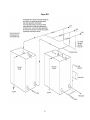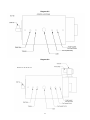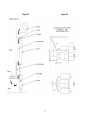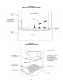
1
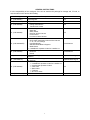
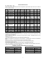
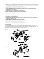
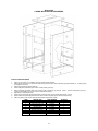
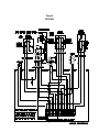
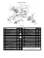
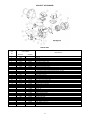
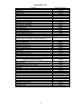
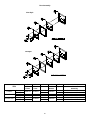
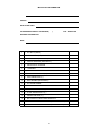
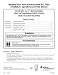
INSTALLATION, OPERATING and SERVICE MANUAL NEWMAC SOLID FUEL BOILER MODEL BC 160 NEWMAC BOILER OIL SECTION O-95, 115, 140, 155, 170 ALL INSTALLATIONS MUST BE MADE IN ACCORDANCE WITH LOCAL & STATE CODES WHICH MAY DIFFER FROM THE MANUAL. HEAD OFFICE MARKETING / PRODUCTION Newmac Mfg. Inc. DEBERT AIR INDUSTRIAL PARK, LANCASTER CRESCENT P.O. BOX 9, DEBERT NOVA SCOTIA, BOM 1G0 TEL: 902-662-3840 FAX: 902-662-2581 EMAIL: [email protected] WAREHOUSE Newmac Mfg. Inc. 430 SPRINGBANK AVE., SOUTH P.O. BOX 545 WOODSTOCK, ONTARIO N4S 7Y5 TEL: 519-539-6147 FAX: 519-539-0048 HOMEPAGE: newmacfurnaces.com NOTICE TO HOMEOWNER: READ THESE INSTRUCTIONS SAVE THESE INSTRUCTIONS 156156 2210042 OCTOBER 2008 Subject to change without notice Printed: _______________________ GENERAL INSTRUCTIONS It is the responsibility of the consignee of the unit to examine the package for damage and, if found, to note the same on the carriers bill of lading. Package #1 - (P/N 5020001) #2 – (P/N 5020005) #3 - (P/N 5020006) #4 - (P/N 5020008) #5 - (P/N 5020002SS) #6 - (P/N 5400025) #7 - (P/N 5020007) #8 – (P/N 5020017) #9 - (P/N 5020009) #10 - (P/N 2190047-J) Description Water Jacket c/w Doors Draft Regulator Ashpit c/w Door Box Containing: Casing and Insulation Tube Brush & Handle Box Containing: Stack Box Stack Gasket Draft Fan & Wire Harness Control Panel Limit Control Wire Harness Box Containing: Oil Chamber Attachment & Burner Wire Harness 2 – 8” x 16 1/4” Castings Heat Shield Assly Stainless Steel Baffle & Supports WMO Switch 1 – L4063B1007 Aquastat c/w Well or L4081B1112 Oil Burner Package: Oil Burner Nozzle Grates, Grate Support, Shaker Handle, Ashdoor Air Deflector Shaker Grates, Grate Support, Shaker Handle, Ashdoor Air Deflector Control Package: 1 – L4063B1007 Aquastat c/w Well or L4081B1112 1 – L6007A1029 Aquastat c/w Well 1 – Filler Valve 1 – Relief Valve 1 – Tridicator 1 – N.O. Zone Valve 5 GPM Domestic Hot Water Coil 1 Included With All All All All Combinations Combinations Optional Grate Pkg #1 Optional Grate Pkg #2 All Optional BOILER IDENTIFICATION BC – Boiler, Wood – Coal O-95,-115,-140,-155,-170 following the letters designates the approximate output of the unit in 1,000’s of B.T.U.’s on the oil section. Model Oil Burner 0 – 95 0 – 115 0 – 140 0 – 155 0 - 160 0 - 170 F-AFC-2-8 F-AFC-2-8 F-AFC-3-8 F-AFC-3-8 F-AFC-3-8 F-AFC-3-8 Model Oil Burner 0 – 95 0 – 115 0 – 140 0 – 155 0 - 160 0 - 170 AFG-AF81YYHSSS AFG-AF81YYHSSS AFG-AF81YYHSSS AFG-AF81YYHSSS AFG-AF81YYHSSS AFG-AF81YYHSSS Model Oil Burner 0 – 95 0 – 115 40 F5 40 F5 40 F5 40 F5 40 F5 40 F5 40 F5 0 – 140 0 – 155 0 - 160 0 - 170 BTUH BTUH Nozzle Pump Insertion Output Input (Monarch) p.s.i. inches 99,000 115,000 143,000 154,000 170,000 170,000 118,490 139,400 174,250 188,190 209,000 209,100 0.85 (80ºR) 1.00 (80ºR) 1.25 (80ºR) 1.35 (80ºR) 1.50 (80°R) 1.50 (80ºR) 100 100 100 100 100 100 5-3/8” 5-3/8” 5-3/8” 5-3/8” 5-3/8” 5-3/8” BTUH BTUH Nozzle Pump Insertion Output Input (Delevan) p.s.i. inches 98,000 115,000 141,000 152,000 168,000 168,000 118,490 139,400 174,250 188,190 209,000 209,100 0.85 (70ºA) 1.00 (70ºA) 1.25 (70ºA) 1.35 (70ºA) 1.50 (70ºA ) 1.50 (70ºA) 100 100 100 100 100 100 5-3/8” 5-3/8” 5-3/8” 5-3/8” 5-3/8” 5-3/8” Air Shutter Setting 3.0 3.5 4.5 5.5 8.0 8.0 Air Design Band Gross Setting Stack F° 0.5 0.5 0.5 0.5 0.5 0.5 325 375 450 475 530 530 Air Design BTUH BTUH Nozzle Pump Insertion Turbulator Damper Gross Output Input (Delevan) p.s.i. inches Setting Setting Stack F° 99,000 116,000 126,000 141,000 154,000 170,000 170,000 118,490 139,400 153,340 174,250 188,190 209,000 209,100 0.75 (60ºW) 0.85 (60ºW) 1.00 (60ºW) 1.10 (60ºW) 1.10 (60ºW) 1.25 (60ºW) 1.25 (60ºW) 145 145 145 145 150 145 145 5-3/8” 5-3/8” 5-3/8” 5-3/8” 5-3/8” 5-3/8” 5-3/8” 0.5 1.0 2.0 2.5 2.5 3.0 3.0 2.5 1.8 2.1 2.6 2.6 2.7 2.7 325 425 460 510 510 540 540 Beckett Low Firing Rate Baffle (3708) not used. Designation BC-160 was adopted for the oil side of combination oil and solid fuel models with a rated output of at least 160,000 BTU. Use air settings as a guide only. Set burner air to give a trace of smoke. Re-adjust burner air to CO2 reading by 1 to 1.5 %. Take measurements with the burner cover and air duct installed (if any). See burner manufacturer’s instructions for more information. If settings differ, use those on the appliance label. Riello burner insertion is measured without the burner flange gasket installed. Beckett and Aero burner insertion is measured with the burner flange gasket installed. Oil not heavier than #2 furnace oil. Close oil burner supply valve if unit is to be shut down for a prolonged period of time. If the unit is installed in an enclosed area (boiler room), ventilation must be provided for the burner – minimum of one square inch for every 1,000 B.T.U. MINIMUM CLEARANCE FROM COMBUSTIBLE SURFACES BC - 160 ONE SIDE OTHER SIDE FRONT REAR FLUE FLOOR BCO SERIES 6 inches 24 inches 48 inches 24 inches 18 inches Non combustible ONE SIDE OTHER SIDE (oil burner) FRONT REAR FLUE FLOOR 2 6 inches 24 inches 48 inches 24 inches 18 inches Non combustible BOILER INSTALLATION THIS BOILER MUST BE INSTALLED BY A QUALIFIED INSTALLER. To insure the boiler is on a level foundation and above any possible dampness, a concrete pad is recommended. The ash pit and boiler are then set on this pad. We recommend a layer of split firebrick be placed in the bottom as shown in diagram 1. The cracks between the ash pit and boiler should be sealed with a substance such as refractory cement in order to allow the unit to operate at peak efficiency. Flue pipe must be a minimum of 26 gauge material. Every 90º elbow gives approximately the same resistance as 10 feet of pipe so install as close to the chimney as possible so that a minimum of pipes and elbows may be used. This will promote better draft and reduce creosote build up. For the combination unit, install the oil burner box and oil burner (remove the plate and cut square opening in gasket). This is illustrated in diagram 3. Install controls, draft fan, etc. as shown in diagram 15 and connect wiring as shown in diagram 7, 8, 9, 10, 11A, 11B, or 12. Suggested piping is illustrated in diagrams 13A, 13B, 14A & 14B. If boiler is used as a wood boiler alone, connect in conventional way. For the combination unit the installation must conform with the regulations of the local authorities having jurisdiction with the applicable Electrical Code, and with the regulations in C.S.A. Standard B139, B365 and according to N.F.P.A. #31 “Standards for the Installation of Oil Burning Equipment,” and the National Electrical Code N.F.P.A. #70. Wood storage should conform to local bylaws. This unit is not for use in mobile homes. This boiler must be connected to a chimney flue with a minimum inside dimension of 8” x 8” square or 8” round. No other appliance should be connected to this chimney flue. The chimney must be approved for wood burning appliances. Do not use a flue pipe damper with this unit. The flue pipe connections must be secured with metal screws and have as few elbows as possible. IMPORTANT The Boiler system must include both a dump zone to relieve excess operating capacity and a safety gravity feed zone that operates to reduce excessive boiler temperatures during EMERGENCY POWER FAILURES. These two (2) individual operating requirements can be achieved as either a single (1) zone or multiple zones. These zones must have the ability to dissipate at least 10% of the rated boiler capacity. The Boiler must be installed on a closed system and must be grounded. This Boiler must have corrosion inhibitor in the water and an air separator must be used to eliminate air in the Boiler System. NEWMAC MFG. INC. COMBINATION OIL, WOOD & COAL BOILER OPERATING SEQUENCE – (See Diagram 7) WOOD (COAL) When starting a wood fire in the Newmac Boiler, turn toggle switch 5 to the OFF or wood only position. The dual aquastat 2, set at 180ºF, will cause the draft fan to operate. When the boiler water temperature reaches 180ºF it will shut the draft fan off. If a zone thermostat calls for heat, the zone valve will open and when it is open the auxiliary contacts will make energizing relay 7. In the case of only one zone the thermostat will energize relay 7 direct. This action starts the circulating pump, which circulates water to the house heating rads. If the boiler temperature drops below 160ºF, the circulator will stop until the heating media catches up. After the wood fire has brought the boiler up to temperature or has passed the 170ºF mark, switch 5 may be placed in the automatic or on position. 3 Automatic position allows the oil burner to come on if the wood fire, because of not being adequately charge, permits the water temperature to drop below 170ºF. While the oil burner is operating, relay number 6 is energized, interrupting the draft fan maintaining oil burner efficiency. When the boiler temperature reaches 170ºF the oil burner stops, allowing the draft fan to start again to stimulate the wood fire. If oil only is to be used for a period of time toggle switch 4 should be moved to off or oil only position. If the boiler temperature reaches the temperature setting of aquastat 3, the dump valve(s) (N.O. valves) open to each zone and the circulator starts, helping to distribute the excess heat throughout the house. The latter should only happen if someone inadvertently overfires the unit. OIL With the boiler water temperature below 170ºF open the line switch, turn toggle switch #4 to “OIL ONLY,” remove the air bleed plug from the pump (refer to Diagram attached to pump): A. Open oil supply valve B. Place a container in position to catch foam C. Close the line switch and after pure oil is emitted, open the line switch and replace bleed plug D. Close the line switch and the oil burner should run normally after a few seconds If the unit fails to start check: A. Power supply B. Thermostat and circuit C. Correct wiring D. Motor thermal switch If the unit starts but goes out on safety check: A. Oil supply B. Ignition (electrodes and transformer) C. Cell If unit goes out on safety, do not push the reset button for at least ten minutes. Do not push the reset button more than once before correcting the cause. Adjust oil burner air control so that a #1 or less smoke is arrived at by means of a smoke test. The damper in the wood firedoor must be closed during this procedure. If a smoke tester is not available, slowly close the air adjustment until the fire becomes smokey. Slowly open the air adjustment until there is a small amount of smoke on the flame tips. By means of the barometric draft regulator – adjust to a -.03 draft at the chimney. This must be done by means of a draft meter. The maximum draft is not to be more than -.05 as damage can result to the boiler when used as a gravity unit. The test must be made between the flue collar on the boiler and the draft regulator. A flue-gas analysis should be made and the unit adjusted so that between a 8% and 10% 2 CO is registered. By means of a slide Draft Control above the fire door, you can control the amount of combustion air allowed into the fire box. Move this slide plate to the open position that allows sufficient combustion air in for the type of solid fuel you are burning. For added efficiency, when heating with oil only, close the slide plate and adjust your solid fuel thermostat to its lowest temperature setting. FURNACE LABEL ILLUSTRATION DRAFT CONTROL OIL ONLY SOLID FUEL CLOSED MINIMUM MAXIMUM 4 For safe operating procedures for solid fuel operation, refer to the notice label on the furnace. The furnace room must have adequate air for combustion. If the unit is in a confined space, one square inch of free air access for every 1,000 BTU must be provided. Use a chimney suitable for solid fuel which must be kept free of accumulation of soot and ash Accumulations of soot and ash not only create a fire hazard but cause poor efficiency In case of a soot fire, move all thermostats to their lowest setting, close the barometric draft regulator and call the fire department. OIL BURNER OPERATING INSTRUCTIONS GENERAL CARE This burner is fully automatic. All adjustments have been carefully set and should not be changed. Keep burner free from excess dirt and moisture. Any oil leaks, however small, should receive immediate attention. The oil filter should be cleaned once a year by the service man. The motor should be given a few drops of light oil two or three times a year. No other parts require lubrication. FUEL The supply tank should be kept at least one-quarter full. Outside underground storage tanks if not equipped with a special gauge, are gauged by a stick. Recommended grade of fuel: No. 2 Furnace Oil. CAUTION 1. Do not use gasoline, crankcase or any oil containing gasoline 2. Do not tamper with the unit or controls, call the service man 3. Do not attempt to start burner when excess oil has accumulated, when the heating unit is full of vapour, or when the combustion chamber is very hot 4. Do not burn garbage or paper in heating system, and never leave paper or rags around the unit HEATING PLANT Give you heating unit the proper care and attention. The use of a boiler as an incinerator is not recommended. Heating unit flues should be kept clean for economical operation. Dampers are set by installation men and should not be changed. Free ventilation must be permanently provided in the room where the burner installation is made. CONTROLS The operation of the burner is normally controlled by room thermostat, which may be set for any temperature desired, usually 20ºC (68ºF). If a higher or lower temperature is desired, the indicator should be moved to the proper point on the scale. To shut down burner at any time, turn main switch to off position. SUMMER SHUT DOWN When burner is not to be used during the summer months turn off burner main switch. If the heating unit room is damp protect burner against dirt and moisture with light cover. SAFETY SHUT-OFF An emergency oil shut-off valve should be installed by local ordinance. Always keep the valve shut off if the burner is shut down for an extended period of time. SERVICE If burner fails to run when the thermostat or other operating control is calling for heat, see that the main switch is turned on and that fuses are not blown. Be sure there is oil in the supply tank and that the electric service to the building has not been temporarily interrupted. Press button on burner control box one time only and if burner still fails to start call the service man. A periodic inspection of the burner is recommended. 5 BURNER TROUBLE SHOOTING Smoke and Soot Insufficient air for combustion Improper mixing of oil and air Lack of air velocity and turbulence Grade of oil too heavy Nozzle worn, clogged, loose, insert loose, improper gallon rate or spray angle Oil pressure too low After drip due to defective pressure regulating valve cutoff Nozzle too far back in blast tube Burner set too far forward Flame striking chamber walls Fan dirty, or loose Operating period too short Insufficient draft Chimney too small, dirty, obstructed Breeching reduced in diameter Motor not up to speed Over fired Loose or defective coupling Odors Oil leaks Oil spilled Poor cutoff on Pressure regulating Valve Poor grade of oil Dirty chimney Boiler sections not Properly sealed Draft control stuck In open position Openings between Smoke pipe joints Lack of air for Combustion Improper oil and air mixture Over fired Dirty nozzle Defective nozzle Noise (mechanical) Fan noise Loose air shutter Burner not mounted Securely Pump gears worn Dirty strainers Obstructed suction Line Air in oil line Defective coupling Burner resting on oil line for support Tank hum (anti-hum Valve) Motor insecurely Mounted Motor bearings bind (lubricate) Pump and motor shaft misaligned Transformer Defective - hum Draft control Vibrating Relay hum – clapper not seating securely Housing out of Alignment. (New Housing needed) Noise (combustion. pulsations) Insufficient draft at breeching or over the fire Chimney dirty, too small, or obstructed Draft control improperly adjusted or locked in open positiom Nozzle too large overfired Oil pressure too low or excessively high Insufficient mixing of air and oil Lack of primary air, fan blades dirty Static pressure in blast tube too low Operating periods too short Nozzle clogged Nozzle too far forward Wrong spray angle Flame impingement Puffback Delayed ignition Improper electrode setting Transformer defective Voltage drops when burner starts Loose ignitors Porcelain insulators carbonized High tension leads loose, insulation defective, or grounded Oil spray defective Nozzle dirty, loose, or too far back in blast tube Pump pressure too low After drip due to poor cutoff Oil leaking into chamber Excess air High draft Primary air velocity too great Water in oil High oil consumption Too much excess air – low CO2 Improper mixing of oil and air by air handling parts lack of turbelence Air leaks through Boiler Boiler sooted up Boiler priming and foaming due to dirty water Building radiation or ducts too small Building heat losses high, needs insulation Poor or excessive draft High stack temperature Overfired – nozzle too large Firing periods too short Nozzle too small Oil leak at buried tank or in buried suction or return line Oil pressure too low Thermostat in wrong location, setting too high; wrong differential Defective radiator vent valves Boiler or furnace too Insufficient domestic hot water Aquastat set too low or needs calibrating Aquastat contacts dirty Generator or instantaneous coil too small Storage tank too small Coil not submerged in boiler water Boiler water level too low OPERATING Flue Draft The flue draft must be -.03” W.C. to -.05”W.C. If the -.05”W.C. is exceeded a power failure situation could cause a solid fuel fire to burn out of control. BURNING WOOD See pages 10 - 12 for the best types of wood to burn. In order to increase the capacity of the boiler firebox for burning wood, the grates may be removed, the base lined with firebrick as shown in diagram #1, and the fire built directly on the firebrick floor of the unit. Grates are required when burning coal but wood burns more efficiently without grates. Turn the control box toggle switch marked Oil to “Automatic” and the toggle switch marked “Wood Only” this will start the combustion air draft fan. During the initial start turn the draft fan off by means of the switch located on the fan itself. Place paper and wood kindling in the firebox and ignite it. Once the wood begins to burn, start the draft fan by turning the switch located on the fan to the “On” position. Once a good base fire is established fill the firebox with wood. After the water temperature reaches 170ºF turn the control box toggle switch marked “Wood” to Automatic. Automatic position allows the oil burner to come on if the wood fire (because of not being adequately charged) permits the water temperature to drop below 170ºF. *A small intense fire is preferable to a large smoldering fire, to reduce the buildup of creosote. 6 COAL BURNING TIPS Burn ONLY anthracite (hard) coal of the “chestnut” size. Bituminous (soft) coal is not recommended because it has a high ash and sulphur content which means more cleaning and greater pollution. Also bituminous coal produces excessive smoke and an excessive amount of dirt and ash which will plug the heating unit and the flue pipe possibly causing smoke damage or danger of carbon monoxide poisoning. Coal is not as easy to burn as wood. It requires patience, and a very specific and regular procedure of loading, shaking, adjusting, etc. If you do not follow the correct procedure, the coal fire will go out. This can happen in a very short space of time and once the process of extinction has started, it is almost impossible to reverse. After a coal fire goes out, all the coal must be emptied from the boiler and the complete starting process must be repeated. The coal-burning learning process is often long and frustrating, but once the proper procedure is established and followed, coal burning becomes a reasonably simple process, with the benefits of long burn times and evenness of output over the entire length of burn. STARTING UP A NEW FIRE The flue draft must be -.05” W.C. to allow combustion gases to flow freely out the chimney. Use paper and dry kindling to start the fire. Add small compact pieces of hardwood when the kindling is burning hot. Keep the draft slide plate in the ash door fully open to establish a hot fire. The ash door may be opened for start-up. However, close the ash door before opening the fire door to prevent smoke from emitting out the fire door opening. When a substantial bed of red coals is built up, start adding coal, small amounts at a time. Continue adding small amounts of coal until there is a solid bed of burning coal. Do not add too much at on time. Allow sufficient time between each small loading (at least 10 to 15 minutes) so that each loading has time to thoroughly ignite before the next load is put in. For maximum burning efficiency, always fill the furnace to the highest level possible. A deep bed of coal always will burn more satisfactorily than a shallow bed. Keep the draft fan running until you are sure the fire is continuing to burn hot. If the ash door has been opened, close it to prevent overfiring, which can severely damage the unit. LOADING Coal should be added to the fire at least every twelve hours. Coal never should be added unless there is a reasonably hot fire. If the fire is burning hot and there is a deep bed of coals, full loads of coal can be added at any time. However, if there is not a deep bed of coals, it is best to add small amounts of coal at first. SHAKING Shaking should be done only with a hot fire. Shaking should be done at least once a day, but not more than twice a day. Best results from shaking will occur if short “choppy” strokes are used rather than long even strokes. The amount of shaking is critical. Too little or too much can extinguish a fire due to blocked air flow. The proper amount normally occurs when the red coals first start to drop through onto the bed of ashes. Be sure that a small amount of ash is left on the grates to protect them from the direct heat of the burning coal. MAINTENANCE Ashes never should be allowed to accumulate in the ash pit so they in any way impede the flow of combustion air to the fire. Excess ash accumulation can cause the fire to go out, and also can cause severe damage to the grates because they cannot cool from a flow of air beneath them. Ashes MUST be removed daily and put in a metal container with a lid. Clinkers can occur in any coal burning unit. They are pieces of fused ash that are hard. They can become large, and therefore cannot be shaken through the grates in a coal furnace. When there is an appreciable accumulation, the fire will go out because insufficient air is allowed to pass through the clinkers to the burning coal. Once clinkers have formed, they can be removed only from above the grates. This usually means the fire must be allowed to die out before they can be removed. 7 Clinker formation can occur from a number of different causes or a combination of causes. Some of these are as follows: Too hot a fire (too much draft); Too shallow a bed of coals; Too deep a bed of coals; Excess shaking; Poking the fire from the top; Poor quality coal – excess ash content; Too little air (draft) after a long hot fire. SAFETY Whenever a loading door is opened, it always should be cracked slightly before fully opening to allow oxygen to enter and burn any combustible gases that are present. Failure to do this could result in sudden ignition of the unburned gases when the door is opened. A boiler never should be filled with excess coal so that the flue gas exit is in any way blocked or impeded. Burning coal generates carbon monoxide. If the flue gas exit is blocked, the carbon monoxide can be forced out of the unit into the room, with possible fatal consequences. Never burn coal in any unit that does not have an airtight, unified chimney system. The boiler should be used only with chimney systems that provide a strong, reliable draft. With the exception of the start-up period, an ash pit door Never should be left open. Do not use an automatic stoker with this boiler. NOTICE IMPORTANT: * * * THIS BOILER MUST BE INSTALLED ACCORDING TO CSA STANDARD B365, “Installation Code for Solid Fuel Burning Appliances and Equipment. The solid fuel side of this boiler is designed to burn wood and anthracite coal only. Proper flue draft must be maintained to allow combustion gases to flow freely out the chimney. FOR SAFE OPERATION Do not use chemical or fluid fire starters. Do not attempt to light a fire when there is oil vapor present. Minimum flue draft -.03” W.C. Maximum flue draft -.05” W.C. Do not burn garbage, manufactured fire logs, gasoline, naptha or crankcase oil. Keep the boiler doors tightly closed except for refueling and cleaning. To maintain boiler efficiency and prevent soot fires, clean the heat exchanger flue pipes and chimney at the end of each heating season and as frequently as required during the heating season to prevent soot accumulation. To clean boiler tubes open top access door and clean tubes with brush provided. The boiler and flue must be in good condition. Turn off power to the boiler when cleaning the boiler and flue. Do not store fuel or combustible material within the boiler clearances. Do not use salt wood (driftwood gathered from the seashore). To Prevent Damage Do not set the flue draft above -.05” W.C. Do not open the furnace door slide plate damper during normal operation. Boilers with grates must have ashes removed daily. SPECIAL PROCEDURES Power Failure (1) To control the fire open the slide plate damper in the boiler door. THIS DAMPER SHOULD BE CLOSED FOR NORMAL OPERATION. (2) Do not load the fire box higher than halfway up the fire box. Soot Fire Close all sources of air that can reach the fire through the boiler and draft regulator. Be sure the draft fan above the fire door is turned off and the draft fan damper is closed. Do not attempt to take the flue pipes down until the fire has been completely extinguished. 8 Runaway Fire This can be caused by too high a flue draft or excessive fuelling. (1) Close all sources of air to the boiler. Be sure draft fan is turned off. (2) Set the barometric draft regulator wide open to reduce draft. PREPARATION OF WOOD ONCE I HAVE MY WOOD AT HOME, HOW DO I PREPARE IT FOR BURNING? The wood must be cut to length to suit the firebox of the stove, furnace, or fireplace in which it is to be burned. An 8’ log may be cut into four, six or eight pieces, depending on the desired length. Splitting the wood greatly facilitates drying and reduces the wood to a more manageable size. HOW MUCH MOISTURE IS CONTAINED IN WOOD? Many softwoods have a moisture content in the vicinity of 55 per cent when they are freshly cut. The popular hardwoods have moisture contents of about 45 per cent. Air-dried wood has a moisture content of about 15 per cent and kiln-dried wood may have a moisture content of less than 10 per cent when it is fresh from the kiln. WHAT CAUSES WOOD TO ROT? When wood is cut, it is very susceptible to the growth of fungi, which converts the wood to water, carbon dioxide, and heat, just as a fire does. This rotting decreases the wood’s energy. The fungi are most productive when three conditions are met; the temperature is between 60 ºF and 90 ºF, the wood’s moisture content is above 30 per cent, and ample oxygen is available. Thus, wood does not rot appreciably when it is dry, in the winter, or when it is submerged in the water, but it should not be allowed to lie on the ground during the summer. HOW CAN THIS ROTTING BE PREVENTED? When the wood has been cut into stove wood lengths, and split, it should be piled outside during the months of June, July and August. Two poles should be placed on the ground to serve as rails to keep the firewood off the moist ground and the wood should be piled up in such a way that it is well exposed to the sun and the wind. The moisture content of the wood will drop until it reaches equilibrium with the ambient weather conditions. When the relative humidity is 60 per cent, the equilibrium moisture content is about 11 per cent. When the wood has reached this equilibrium moisture content, it is said to be “air-dried.” Around mid-August, it should be placed under cover so that it will not reabsorb moisture from the rain and snow before it is used. WHY THIS CONCERN ABOUT ALLOWING THE WOOD TO DRY? Green or wet wood is undesirable for several reasons. Green or wet wood tends to mildew and rot which causes a significant reduction of the thermal value. When green or wet wood is burned, it may take 20 to 25 per cent of the thermal value of the wood heat to evaporate and drive off the moisture that is contained. Green wood does not burn easily and, in order to keep the fire burning, it is often necessary to add a lot of fuel and provide excessive draft, thereby decreasing the efficiency of the unit. The excess air needed for combustion must be heated and it escapes up the chimney wasting heat that should be used to heat the house. WHAT IS CREOSOTE? Wood smoke almost always contains some unburned gases and a fog of unburned tar-like liquids. Some of these materials will condense on the inside of the chimney, just as the steam condenses on any cold surface. This condensation is a black, tacky, fluid when first formed. When it dries, it is flaky and shiny. Creosote has approximately the same thermal value as fuel oil. Not only does it reduce the effective size of the chimney, but an accumulation of this material constitutes a serious fire hazard. DOES GREEN WOOD CAUSE CREOSOTE? Yes. Indirectly, green wood does cause creosote. The exhaust gases cool as they rise up the chimney. If the temperature falls below the dew point, any moisture contained in these gases will condense on the inside of the chimney, absorb the various products of incomplete combustion and form creosote. When green wood is burned, the exhaust gases carry a high moisture content in addition, because of the heat 9 required for evaporation, these gases are cooler and more likely to condense than would be the case with dry wood. Charcoal may be found more readily if the unit is overcharged particularly in milder weather. With overcharging (too much wood in unit) the draft fan will be off a greater percentage of time, coals will be formed which will become covered with ash in turn will smother the coals to form charcoal. Any coals in the furnace should be stirred before more wood is added to it. The preceding is an excerpt from a document prepared by the Nova Scotia Energy Council and the Nova Scotia Research Foundation Corporation. CREOSOTE AND CHIMNEY FIRES Wood combustion is never perfectly complete. Wood smoke almost always contains some unburned gases and a fog of unburned tar-like liquids. Some of these materials will condense out of the flue gases onto any surface, which is not too hot. The condensate is usually dark brown or black, and has an unpleasant acrid odor. It is called creosote. If condensed on a relatively cool surface (such as an exterior stovepipe or chimney), the creosote will contain a large amount of water along with the organic compounds, and will thus be very fluid. Water is usually absent if the condensation occurs on surfaces hotter than 150 ºF. The condensation may then be thick and sticky, like tacky paint or tar. Creosote may be found almost anywhere in a wood heating system, from the top of the chimney to the insides of the boiler itself. Creosote which remains in a chimney after its initial formation may later be significantly modified both in physical form and chemical content. The water and the more volatile organic compounds tend to evaporate, leaving the more tar-like substances behind. If these are subsequently heated by the flue gases from a hotter fire (this usually happens), they themselves are further pyrolyzed to the same final solid product that wood is carbon. The physical form is usually flaky, and often shiny on one side. Partially pyrolyzed deposits can have a bubbly appearance. The flakes do not adhere strongly to a stove pipe and thus are easy to brush off; some of the other forms will not budge even under the action of a stiff wire brush. The amount of creosote deposited depends mostly on two factors, the density of the smoke and fumes from the fire, and the temperature of the surface on which it is condensing. Highest smoke densities occur when a large amount of wood in relatively small pieces is added to a hot bed of coals and the air inlet damper is closed. Here, there is considerable pyrolysis of wood, but little combustion, and little air to dilute the smoke. In practice, creosote generation is highest during low-power, overnight, smoldering burns. Smoke densities are least when combustion is relatively complete, which tends to be the case when the amount of excess air admitted to the wood-burner is high. Leaky stoves, open stoves and fireplaces typically have the least severe creosote problems. One way to lower the average smoke density in an airtight stove is to use less wood each time fuel is added, and/or to use larger pieces of wood; in either case, the air supply need not be turned down so much in order to limit the heat output and combustion is likely to be more complete. Of course, if less wood is added, stokings must be more frequent. A related procedure to limit creosote is to leave the air inlet moderately open after adding wood until the wood is mostly reduced to charcoal, and then close the inlet as much as desired. This will promote complete combustion during pyrolysis, when the creosote compounds are being formed, but there will still be a significant heat surge while the gases are burning. Extra air can also be added to the flue gases in the stove pipe; this is what the Ashley creosote inhibitor accessory does. But the net effect of adding dilution air is not obvious or necessarily beneficial. Dilution air will decrease the smoke density, but it will also decrease its temperature. These effects have opposing influences on creosote formation. The National Fire Prevention Association states that dilution air increases chimney deposits. In any case, the cooling effect of dilution air does decrease the heat transfer through the stove pipe and chimney, thus decreasing the system’s energy efficiency. Creosote formation may also depend on the type of wood burned and on its moisture content. Dry hardwoods have a reputation for generating the least creosote, but the quantity can still be very large. No kind of wood eliminates creosote formation. For a given smoke density near a surface, the cooler the surface, the more creosote will condense on it. The phenomenon is very similar to water vapor condensing on the outside of a glass of ice water on a humid day, except for an inversion – condensation occurs on the inside of a chimney, especially when cold air outside makes the inner chimney surface relatively cool. A stove pipe chimney outside a house on a cold day will be wet on the inside with creosote (including a lot of water) virtually all the time. A well 10 insulated, pre-fabricated metal chimney has the least serious creosote problems; its insulation helps maintain higher temperatures on its inner surface, and its low heat capacity allows it to warm up very quickly after a fire is started. Masonry chimneys frequently accumulate deposits at the beginnings of fires and their interior surfaces take a longer time to warm because the construction is so massive. Any type of chimney which runs up the outside of a house is more susceptible to creosote problems than the same type of chimney rising in the houses’ interior, due to the cooling effect of the colder outdoor air on the exterior chimney. Average flue gas temperatures can be increased by minimizing the length of stove pipe connecting the stoves to the chimney. This, of course, will also decrease the energy efficiency of the system, and its often true that measures which decrease creosote formation also decrease heating efficiency. For instance, stoves which have energy efficiencies due to their relatively good heat transfer (e.g. the Sevca, lange 6303 and double barrel stoves) are more likely to have chimney creosote problems precisely because they do such a good job extracting heat from the flue gases. Generally creosote is inevitable and must be lived with. Any kind of chimney deposit decreases the system’s heating efficiency. Soot and dried creosote accumulations have a significant insulating effect; less of the heat in the flue gases is transferred into a house through dirty stovepipe and chimneys. The most annoying problem can be creosote dripping from a stovepipe or chimney, and the most dangerous problem is chimney fires, during which the creosote, or its pyrolyzed residue, burns. Creosote dripping can usually be eliminated. Joints in vertical segments of stovepipe will not leak if, at the joints, the smaller, crimped ends always stick down into the receiving end. (Smoke will not leak out of the joints due to this direction of overlap.) Since this is not the usual orientation for stovepipe, a double male fitting may be necessary at some point to connect the stovepipe to the stove, a prefabricated chimney, or a rain cap. Special drip-proof adapters are available for connecting some sizes of stovepipe to Metalbestos brand pre-fabricated chimneys. Common types of stove pipe elbows can leak creosote due to their swivel joints; rigid and accordion-type leakproof elbows are available. Horizontal or gently sloping sections of stove pipe should be oriented so their seams are on top. Joints between horizontal pipes and/or fittings are the most difficult to seal against dripping. A good high-temperature sealant can sometimes help, but is not guarantee. The joint must also be snug, and well secured with sheet-metal screws. If all joints are made leak-proof, then the creosote will generally drip into the stove, where, when the fire is hot, it will be burned. Chimney fires occur when the combustible deposits on the inside of a chimney burn. The deposits may be ‘raw’ creosote, pyrolyzed creosote, or soot. Ignition requires adequate oxygen, which is usually available, and sufficiently high temperatures the same conditions are for the ignition and combustion of any fuel. Chimney fires are most likely to occur during a very hot fire, as when cardboard or Christmas tree branches are burned, or even when a stove burns normal wood, but at a higher than normal rate. A crackling sound can often be heard at the beginning of a chimney fire. As the intensity of the fire rises, the stove pipe will sometimes shake violently, air will be very forcefully drawn in through the stove, and the stove pipe may glow red hot. A tall plume of flame and sparks can be seen rising from the top of uncapped chimneys. The most effective way to suppress a chimney fire is to limit its air supply although both water and salt are sometimes suggested. If a relatively air-tight stove is the connected appliance, this is easily done by closing the stove’s air-inlet dampers, if all the stove pipe and/or chimney joints are tight, and if no other appliance is connected to the same flue. In a properly designed and maintained chimney, the only potential hazard related to chimney fires is ignition of the building’s roof or surroundings due to sparks and burning embers coming out of the top of the chimney. A spark arresting screen can decrease, but not eliminate this possibility, but spark screens themselves are often not suitable for use with wood fuel because they can become clogged. The chimney itself and the stove pipe, when properly installed, are intended to withstand an occasional chimney fire without danger of ignition of their surroundings. During a chimney fire check the roof and surroundings and possibly wet down critical areas. If the chimney may not be up to safety standards, one should also keep a close watch on all surfaces near the chimney. Some people start chimney fires fairly frequently, as a means of chimney cleaning. This deters very intense chimney fires and the small ones which do happen are always under a watchfull eye. Under some circumstances, this practice may be reasonable, but generally it is a risky method to keep a chimney clean. There is always some danger of a house fire, but in addition, any chimney fire is wearing on a chimney; the high temperatures increase the corrosion rate of metals and the thermal expansion of masonry materials encourage crack formation and growth. 11 Chemical chimney cleaners are available. Opinions on their effectiveness vary, but apparently when used regularly, and as directed, they work, and do not damage chimneys. The usual chimney-cleaning method is the oldest human energy and some kind of mechanical tool. A stiff wire brush, a heavy chain (perhaps in a bag) hung with a rope and worked up and down from the top of the chimney, and very small brushes have all been used. Professional chimney sweeps are also reappearing. Some people clean yearly, others after every few cords of wood burned, but there are so many factors influencing creosote build up that such generalizations are not appropriate in most particular cases. In new installations, or when changes occur (such as a different stove) the chimney should be checked frequently (after 2 weeks, then after a month, then after another 2 month, etc.) until it is clear how frequently cleaning is needed. The preceding is an excerpt from “THE WOODBURNERS ENCYCLOPEDIA” published by Vermont Crossroads Press, Inc. – December 1976. WOOD IS A SAFE, CLEAN AND ECONOMICAL FUEL Species Hickory Hard Maple Beech Red Oak Yellow Birch Elm Soft Maple Tamarack Cherry Ash Spruce Hemlock Aspen White Pine Basswood Approx. Wt. Per Cord 3595 BTU Per Air Dried Cord 30,600,000 Equivalent Value #2 Heating Oil In Litres 827.4 Cost at $0.25 $206.85 Cost at $0.30 $248.22 Cost at $0.35 $289.59 3075 3240 3240 3000 2750 2500 2500 2550 2950 2100 2100 1900 1800 1900 29,000,000 27,800,000 27,300,000 26,200,000 24,500,000 24,000,000 24,000,000 23,500,000 22,600,000 18,100,000 17,900,000 17,700,000 17,700,000 17,000,000 784.6 752.4 738.7 709.2 662.8 649.2 649.2 635.5 611.4 490.1 484.1 483.2 462.8 459.6 196.15 188.10 184.67 177.30 165.70 162.30 162.30 158.87 152.85 122.52 121.02 120.80 115.70 114.90 235.38 225.72 221.61 212.76 198.84 194.76 194.76 190.65 183.42 147.03 145.23 144.96 138.84 137.88 274.61 263.34 258.54 248.22 231.98 227.22 227.22 222.42 213.99 171.53 169.43 169.12 161.98 160.86 To change litres (l) to US gal. Multiply by .264 For the least amount of wood handling, the wood with the highest heat content is most desirable. An open fireplace can actually refrigerate a house because it sucks in so much cold air which is only partially used for combustion. A carefully designed fireplace makes use of perhaps 10-15% of the heat available; most still going up the flue. The well constructed potbellies get perhaps 20-25% and the automatic, draft regulated, tightly sealed wood heaters get perhaps 50%. Notice that the percentage efficiency goes up as the combustion process becomes more and more controlled. The roaring fire is a complete waste of fuel. The best situation is one where the combustion chamber if gas-tight. This allows a controlled fire that toasts the wood and puts the right quality of wood gas in the right place and at the right temperature for optimal combustion and heat transfer. THE NEWMAC COMBINATION OIL AND WOOD FURNACE toasts the wood to charcoal and the charcoal burns to dust leaving a minute amount of residue. From the above heat values, it can be seen that a cord of Hickory wood is equivalent to $248.22 (@ $0.30 per litre) worth of oil, over twice as much as you would pay for a cord of wood. Without taking into account all the free wood that is available, EFFICIENT WOOD HEATING cuts your heating costs in half. 12 Diagram #1 BOILER INSTALLATION ON NON-COMBUSTIBLE FLOOR 13 Diagram #2 NON-COMBUSTIBLE BASE Note: This unit is designed and approved to be placed on a non-combustible floor. This diagram shows how such a typical base can be made if the boiler room has a combustible floor. Consult also CMHC Bulletin NHA 5178 78/08, Heating with Wood Safely. Also consult local authorities before installing units in rooms with combustible floors. 14 Diagram #3 STACK AND OIL CHAMBER INSTALLATION INSTALLATION PROCEDURE 1. Install gasket between rear boiler wall and retainer. If unit is BCO series cut a hole 9 ½ x 9 ½” in gasket to provide passage from oil chamber to boiler (use opening in boiler as a guide). 2. Place cover plate for BC-160 or oil chamber for BCO series from top of unit between gasket and retainers, allowing it to rest on bottom retainer, tighten bottom 6 set screws to hold it in place. 3. Place gasket and stack box from top of unit between boiler and retainers and position so top of box lip is even with tip of retainers. Tighten set screws to hold it in place. 4. Install oil burner on studs on side of chamber box with 3 washers and nuts provided. 15 HEAT SHIELD INSTALLATION Step 1: Slide heat shield on over oil section Step 2: Secure in place at burner side with angle bracket and two screws Step 3: Secure opposite end using hook bracket and two screws 16 OIL FIRED BLOCKED VENT SWITCH - MODEL WMO-1 When installed on the oil chamber assembly according to these instructions, the manually reset WMO-1 blocked vent switch is designed to shut off power to the oil burner if the hot flue gases in the chimney vent connector pipe back up sufficiently to activate it. The WMO-1 switch is required on new Newmac oil-fired and combination furnaces or boilers installed in Canada. It must be installed by a qualified installer in accordance with the manufacturer's installation instructions. Electrical wiring must be in accordance with applicable codes and the Canadian Electrical Code. Before leaving the appliance check that the WMO-1 switch and its cover are tightly secured. Items supplied with this kit, Newmac Part 2040300: Blocked Vent Switch Assembly-Model WMO-1 Installation on the Oil Chamber Assembly - Fig. 1A - Newmac combination wood/oil or coal/oil fired boiler. 1. Remove the 5/8" or 7/8 diameter plug or knockout in the oil chamber assembly. Drill at least four 9/64" diameter holes in the oil chamber assembly at the locations shown. 2. Insert the heat transfer tube assembly (5) into the 5/8" or 7/8" diameter hole. Check that the heat transfer tube assembly (5) is sealed against the oil chamber assembly by installing 4 metal screws (7). CAUTION: Disconnect the electrical power supply before wiring the WMO-1 assembly. 3. See Diagram #8: Using suitable AC90 flexible (BX) conduit or equivalent, wire the WMO-1 switch in series with the appliance limit circuit. Connect at the appliance junction box. 4. Check the operation of the WMO-1 switch before leaving the appliance. The WMO-1 switch is reset by pushing the square red button. Installation on the Oil Chamber Assembly - Fig. 1B - Newmac combination wood/oil or coal/oil fired boiler. 1. Remove the 5/8" or 7/8 diameter plug or knockout in the oil chamber assembly. Remove one of the securing nuts (7) from the tube of the WMO-1 assembly. Tighten the remaining nut (5) onto the tube as far as possible. 2. Insert the threaded tube end into the 5/8" diameter hole in the oil chamber assembly. Install the first securing nut onto the tube on the inside of the oil chamber assembly. Tighten securely. CAUTION: Disconnect the electrical power supply before wiring the WMO-1 assembly. 3. See Diagram #8 in the Installation, Operating and Service Manual. Using suitable AC90 flexible (BX) conduit or equivalent, wire the WMO-1 switch in series with the appliance limit circuit. Connect at the burner junction box. 4. Check the operation of the WMO-1 switch before leaving the appliance. The WMO-1 switch is reset by pushing the square red button. WMO-1 Blocked Vent Switch Check Note: take appropriate precautions - this test can produce soot, smoke and fumes. The appliance should not be left unattended during the test. 1. With the appliance shut down, block the vent pipe at the downstream (chimney) side of the barometric damper. 2. Start the appliance. 3. The WMO-1 switch should stop the oil burner in less than 10 minutes. 4. After the test, turn off the appliance and let it cool. 5. Remove the blockage from the vent pipe. 6. Reset the WMO-1 switch by pushing in the square red button until it clicks. 7. Ensure that the appliance is in a safe condition. Maintenance and Cleaning The WMO-1 switch assembly should be checked and cleaned at least once a year and after any time the switch has shut off the burner. Cleaning procedure - See Figure 1A 1. Switch off the electrical power to the appliance. 2. Remove the WMO-1 cover (2). 17 3. Remove the two mounting screws holding the control box (4) to the heat transfer tube assembly (5). 4. Using a suitable soft brush or cloth carefully clean any soot from the surface of the thermodisc sensor and the inside of the heat transfer tube assembly (5). 6. Replace the control box (4) and secure with its mounting screws. 7. Check that the wiring is in good condition and secure. 8. Check that the heat transfer tube assembly (5) is sealed against the oil chamber assembly by tightening the 4 metal screws (7). 9. Replace the cover (2) and tighten the mounting screws (1). 10. Check the operation of the WMO-1 switch as described above. Cleaning procedure - See Figure 1B 1. Switch off the electrical power to the appliance. 2. Remove the WMO-1 cover (2). 3. Remove the two mounting screws for the thermodisc temperature sensor (3). 4. Carefully pull the sensor to one side. 5. Using a suitable soft brush or cloth carefully clean any soot from the surface of the sensor and the inside of the heat transfer tube. 6. Replace the sensor and secure with its mounting screws. 7. Check that the wiring is in good condition and secure. 8. Check that the heat transfer tube and its securing nuts are tight. 9. Replace the cover and tighten the mounting screws (1). 10. Check the operation of the WMO-1 switch as described above. Troubleshooting If for any reason the WMO-1 switch shuts the appliance down during operation, the cause of the shut down should be investigated and corrected before resetting the switch and restarting the appliance. The blockage switch is reset by pushing the square red button until it clicks. Fig. 1A Fig. 1B 18 Diagram #4 CASING INSTALLATION PROCEDURE INSTALLATION PROCEDURE 1. 2. 3. 4. 5. 6. 7. 8. 9. Place 30 x 110 piece of ½” insulation over top of boiler and down sides. Place bottom rear panel (1) in place with inlets through holes in panel. Rear extension (8) is placed below (1). (1) and (8) may be shipped in one piece. Place top rear panel (2) above stack box. Fasten side panel extensions (9) to bottom of side panels (3) and (4). Place side panel (3) against boiler, and over the ends of panels (1), (2) and (8). Insert 1 screw to hold panels (2) & (3), 2 screws to hold panels (1) & (3) & 2 screws to hold panels (8) & (9). Repeat step 4 with side panel (4). Fasten top front panel (5) above access doors to panel (3) with 1 screw and to panel (4) with 1 screw. Fasten bottom front panel (6) below fire door with 2 screws into panel (3) and 2 screws into panel (4). Place top panel (7) over top of other panels and fasten in place with screws. ITEM 1&8 2 3 4 5 6 7 9 DESCRIPTION Bottom Rear Panel Rear Panel Liner Top Right Side Panel Left Side Panel Top Front Panel Bottom Front Panel Top Panel Side Panel Extension PART NUMBER 4150038 4150037 4150029 4150030 4150032 4150036 4150031 4150033 19 QUANTITY 1 1 1 1 1 1 1 2 Diagram #5 FLUE PIPE CONNECTION Diagram #6 MINIMUM INSTALLATION CLEARANCES 20 Diagram #7 CONTROL PANEL 21 Diagram #8 FIELD WIRING 22 Diagram #9 23 Diagram #11A 24 Diagram #11B 25 Diagram #12 WOOD ADD-ON WIRING 26 Diagram #13A 27 Diagram #13B 28 Diagram #14A TYPICAL PIPING - ZONING WITH CIRCULATORS 29 Diagram #14B TYPICAL PIPING - ZONING WITH ZONE VALVES 30 Diagram #15 Diagram #16 31 Diagram #17 Diagram #18 32 Diagram #19 SHAKER GRATE INSTALLATION PROCEDURE 33 Diagram #20 GRATE INSTALLATION PROCEDURE Diagram #21 CASTING INSTALLATION 34 BAFFLE RETAINER AND BAFFLE INSTALLATION STEP 1: Position first cast baffle in boiler on supports as shown STEP 2: Put baffle retainers in place by sliding one along each edge of the baffle BAFFLE RETAINER STEP 3: Once one baffle and baffle supports are in place slide second cast baffle into place STEP 4: Inserting stainless steel baffle. Slide baffle through the firedoor and position so that the short brake on the steel is closest to the front and pointing up. Raise the front of the baffle high enough that the edge can be slid under the cast baffle. Once the stainless steel baffle is under the edge of the cast baffle, continue to push the stainless steel baffle until the bend comes up tight against the front of the cast baffle. Note the baffles and retainers may have to be lifted slightly to slide the stainless steel baffle under it BAFFLE FRONT VIEW 35 TOP VIEW FROM FRONT AERO F-AFC BURNER PARTS LIST Item Part Name & Description No. 1 F housing 2 Blast tube, 8" (2001 & later) Blast tube, 7" (Before 2001) 3 Mounting flange - Standard 4 Air Band assembly 5 Motor: Motor, 1/6 HP, 1725 Motor, 1/8 HP, 1725 6 Fan, 524-316 7 Flexible metal-end coupling 8 Fuel Pump, 1725 RPM Danfoss 071N1152 Suntec A1VA7112 9 Transformer, Allanson, 2721-456, 10000V Ignitor, Allanson 2275-456, 17.5 kV 10 End cone: AFC-2 AFC-3 11 Nozzle adaptor 12 Oil pipe, aluminum (specify blast tube length) 13 Electrode holder 14 Electrodes (with porcelains) 14A Bus bars (specify length) 16 Jam Hex nut Primary Relay Honeywell R8184G Honeywell R7184A Honeywell R7184B White Rodgers 668-603 CAD Cell Honeywell C554A1455 Part Number Aero Newmac 65000 2090006 2090003 65004 65518 Item No. 17 100 18 19 20 21 23 24 25 27 27 28 29 31 A98866 2020010 30044 65046 B1540 2060001 2090002 2090066 65007 2110002 65008 2110003 30038 32 33 34 35 65019 Part Name & Description Knurled lock nut 8" Electrode assembly (11 to 17) 7" Electrode assembly AFC end cone screws Blast tube screw (specify length) Raceway Motor screws Transformer lock down screw Transformer hinge screws Slide Plate Air band locking screw Air band locking nut Oil line assembly Compression elbow, 90 degree Nozzle (specify gph, angle, pattern) 1.35 x 80 R Standard Spacer, 1 ½" Spacer, 2 ½" Oil burner mounting gasket, 1/8" Base assembly (including brackets & nuts) Carton - complete Part Number Aero Newmac 65018 2090001 2090014 30053 65062 30054 30063 30062 65017 30054 30001 65524 30073 2100166 30018 66004 2110022 2080050 2090010 30037 2010002 2090068 2090069 2010060 2010006 When ordering parts, always give: (1) Model; (2) Part Name; (3) Part Number; (4) Size; (5) Quantity Required. 36 BECKETT AFG BURNER PARTS LIST ITEM NO. 1 2 3 4 8 10 7 9 11 12 13 14 16A 16B 17 18 20 21 22 PART NUMBER DESCRIPTION BECKETT NEWMAC 5877 3709 3492 3493 21844U 51843U 21755U 21877U 51573 51843U 21755U 2090024 21807 2256 5394 21805U 2999U 7456U 7457U 5770 51771U 7006U 3384 5153633BK 24 31517 3416 51770 5880 5941 2060012 2090065 2090072 2090058 2020012 2090056 2090069 2090067 2090064 2010006 2090039 2110009 2090022 2110015 2110016 2080051 2090061 2090044 2100128 2100132 2100129 2100133 2100134 Burner Housing Assembly Air Shutter Air Band Escutcheon Plate Pump Clean Cut A2EA - 6520 Strainer & Gasket Valve Coil (Suntec Part No. 3713824) Valve Stem Suntec Pump c/w Solenoid Valve Strainer & Gasket Valve Coil (Suntec Part No. 3713824) Valve Stem (Includes 2 O Rings) (Suntec Part No. 3773578) Solenoid Valve Repair Kit (Suntec Part No. 991375) Valve cordset Pump Nozzle Port Fitting Connector Tube Assembly PSC Drive Motor, 3450 RPM Blower Wheel Primary Relay, Honeywell R7184B Primary Relay, Honeywell R7184P Junction Box Kit Electronic Ignitor (14,000 Volt) Cad Cell C554A1455B Honeywell 3-3/8U Static Plate Blast Tube c/w Welded Flange AFG (7 7/8”) Endcone, F6 Electrode Assembly 8” Ceramic Heat Shield Ceramic Heat Shield Holder Flange Gasket Field Controls AirBoot Low Firing Rate Baffle Adjusting Plate Assy Nozzle, Delavan 0.85 X 70oA Nozzle, Delavan 1.00 X 70oA Nozzle, Delavan 1.25 X 70oA Nozzle, Delavan 1.35 X 70oA Nozzle, Delavan 1.50 X 70oA 37 RIELLO F5 BURNER PARTS LIST ITEM 10 20 21 23 25 26 28 29 33 35 36 49 PART NUMBER RIELLO C7010002 3002279 3007802 3005843 3002280 C7001029 3005855 3005856 3007204 3005844 3005708 C3948974 C7001033 3007568 3006925 C7001013 DESCRIPTION NEWMAC 2090043 2060007 2010045 2010048 2080058 2090041 2090046 2030016 2010034 38 O-ring - pump cover Solenoid Coil Pump Motor Photo cell Primary control 530 SE/C Universal mounting flange Mounting gasket Manual Air Shutter Capacitor 12.5 Uf Fan Blast Tube Assembly Blast Tube Protector Bleeder Valve Stem Parts Bag 24V Relay, Switching (for Riello) BC-160 PARTS LIST Description Airchute (After 1979) Aquastat Well Aquastat, Dual (2 required) Aquastat, Single Ash Pit Complete Boiler Brush Boiler Brush Handle Brick, Cut 1 ¼" x 4 ½" x 3" #5 Box Brick, Full 2 ½" x 4 ½" x 9" #10 Box Brick, Full 2 ½" x 4 ½" x 9" #8 Box Brick, Split 1 ¼" x 4 ½" x 9" #6 Box Bushing ¾" x ½" NPT Casing Package c/w Boiler Brush Cast, Front (Baffle) Combustion Chamber Control Package Door, Access (2003 & After) Door, Ash Complete (2003 & After) Door, Fire Complete (2003 & After) Draft Fan, 100 CFM Dump Zone Valve Gasket - Blank (Used for Oil Chamber, Stack Box & Draft Pouch Gasket) 2 blanks required (1 - Oil chamber, 1 - Stack Box & Draft Pouch) Gasket, Access Door Rope ¾" x 53" (Only sold in 72" lengths) Gasket, Ashdoor Rope ¾" x 60" (Only sold in 72" lengths) Gasket, Coil (2001 & After) Gasket, Coil (Before 2001) Gasket, Draft Pouch (Pre-cut) Gasket, Firedoor Rope ¾" x 71 ½" (Only sold in 72" lengths) Gasket, Oil Chamber (Pre-cut) Gasket, Stack Box (Pre-cut) Grate Package Grate, Front Support Grate, Replacement (4 required) Handle, Cast Shaker Liner, Side Opening (Right & Left) Liner, Top & Bottom Oil Chamber SS c/w Gasket (Replacement All) (Units Prior to 2001 Require 1 ½" Spacer) Poker Pressure Regulator Relay R4222B or equivalent, 120 V Coil (New) Relay R4222D or equivalent, 120 V Coil (Old) Relay R8222D or equivalent, 24 V Coil Relief Valve Rocker Switch SS Oil Section Less Burner c/w Gaskets, Casting, Burner Wire & Aquastat Stack Box (Replacement) Stack Box c/w Gasket & Wiring Tankless Coil, 4 GPM (Before 2001) Tankless Coil, 5 GPM (2001 & After) Transformer Assy, 16 VA or equivalent Transformer Assy, 40 VA Tridicator ½ NPT User's Manual Wire Harness, Aquastat 3 Wire Wire Harness, Aquastat 4 Wire Wire Harness, Burner 39 Newmac Part Number 4060118 2010049 2010011 2010014 5020005 2170010 2170011 5110015 5110003 5110002 5110006 5020006 2170013 2030001 5020009 4160157 4160319 4160320 2040002 2190007 2080015 2080049 2080049 2080044 2080026 2080023 2080049 2080025 2080024 5020007 4060125 2170007 2170006 3030034 3030035 5020002 3080161 2190003 2010016 2010013 2010012 2190004 2200258 5020002SS 5020004 5020008 2190008 2190047-J 4050239 4050240 2190085 2210042 4050190 4050184 4050191 Door Assembly New Style Old Style ITEM Firedoor Ash Door Access Door New style Old style New style Old style New style Old style 1 Air Chute 2 Metal Liner 4060118 3160323 3160437 3160333 3160348 3 Gasket 2080049 2080002 2080049 2080022 2080049 2080028 40 4 Inside Gasket 2080003 2080021 2080021 2080018 5 Spacer 3160366 3160334 3160387 6 Outer & Inner Panel Assembly 3160433 & 3160434 Welded 3160318 & 3160325 Welded 3160435 & 3160436 Welded 3160331 & 3160332 Welded 3160431 & 3160432 Welded 3160346 & 3160347 Welded IMPORTANT HOMEOWNER INSTRUCTIONS 1. AN EMERGENCY POWER SWITCH IS REQUIRED TO BE INSTALLED IN A CONVENIENT LOCATION AT A SAFE DISTANCE FROM THE BURNER. THIS SWITCH INTERRUPTS THE ELECTRICAL SUPPLY CIRCUIT TO THE APPLIANCE. MAKE SURE YOU ARE AWARE OF ITS LOCATION AND THE OFF POSITION IS CLEARLY MARKED. 2. KEEP THE SPACE CLEAR AROUND THE APPLIANCE WITHIN THE SPECIFIED CLEARANCES TO COMBUSTIBLES. 3. ENSURE THE SUPPLY OF COMBUSTION AIR TO THE APPLIANCE IS NOT OBSTRUCTED OR CUT-OFF. 4. MAINTAIN PROPER VENTILATION OF THE APPLIANCE AREA. 5. MAINTAIN FREE AIR FLOW THROUGH THE RETURN AIR REGISTERS. * 6. CONTACT SERVICE PERSONNEL BEFORE REMODELLING. 7. CONTACT SERVICE PERSONNEL FOR ANNUAL SERVICE AND MAINTENANCE. 8. CONTACT SERVICE PERSONNEL FOR AIR FILTER REPLACEMENT. * 9. CONTACT SERVICE PERSONNEL BEFORE AND AFTER EXTENDED PERIODS OF APPLIANCE INOPERATION. 10. THE BURNER IS FULLY AUTOMATIC IN OPERATION. ALL ADJUSTMENTS SHOULD BE MADE BY A QUALIFIED TECHNICIAN. DO NOT PUSH THE RESET BUTTON MORE THAN ONCE. CAUTION : DO NOT ATTEMPT TO START THE BURNER WHEN EXCESS OIL HAS ACCUMULATED, WHEN THE APPLIANCE IS FULL OF VAPOUR, OR WHEN THE COMBUSTION CHAMBER IS VERY HOT. 11. CAUTION : DO NOT TAMPER WITH THE APPLIANCE OR CONTROLS—CALL YOUR SERVICE PERSONNEL. 12. DO NOT USE GASOLINE, CRANKCASE OIL, OR ANY OIL CONTAINING GASOLINE 13. ALWAYS KEEP THE OIL SUPPLY VALVE SHUT OFF IF THE BURNER IS SHUT DOWN FOR AN EXTENDED PERIOD OF TIME. 14. DO NOT START THE BURNER UNLESS THE BLOWER ACCESS DOOR IS SECURED IN PLACE. 15. NEVER BURN GARBAGE OR PAPER IN THE HEATING SYSTEM, AND NEVER LEAVE PAPER OR RAGS AROUND THE APPLIANCE. * FURNACES ONLY 41 INSTALLER INFORMATION NAME: COMPANY: INSTALLATION DATE: THE HOMEOWNER SHOULD TELEPHONE ( ) FOR SERVICE OR ADDITIONAL INFORMATION. MODEL: APPLIANCE INITIAL TEST AND SERVICE INFORMATION 1 FUEL INPUT (USGPH) 2 FUEL PRESSURE (PSIG) 3 FLUE PRESSURE (INCHES W.C.) 4 OVERFIRE PRESSURE (INCHES W.C.) 5 NOZZLE ANGLE / PATTERN 6 C0 PERCENT 7 BURNER MODEL 8 FLUE GAS TEMPERTURE (F ) 9 ROOM TEMPERTURE (F ) 10 SMOKE NUMBER (BACHARACH) 11 FUEL GRADE NUMBER 12 WATER PRESSURE 13 SUPPLY TEMPERATURE (F ) 14 RETURN TEMPERATURE (F ) 15 TEMPERATURE RISE (F ) 16 LIMIT CONTROL FUNCTIONING PROPERLY 17 PRIMARY CONTROL SHUT OFF TIME (IGNITION FAILURE) 18 PRIMARY CONTROL SHUT OFF TIME (FLAME FAILURE) 2 O O o o o 42 BC160 B0ILER LIMITED WARRANTY Subject to the following conditions Newmac Manufacturing Inc. warrants the appliance, to the original owner purchaser, under normal use and repair, against defects in workmanship and materials for a period of one calendar year from the date of original installation. This limited warranty does not cover nozzles, filters, etc. that may be contaminated at time of installation. The burner, controls or any other electrical or mechanical components not manufactured by Newmac are warranted for a period of one year from date of original installation by their respective manufacturers; most burners have 3 years. On the date of original installation Newmac warrants for a period of ten (10) years to the original purchaser that the pressure vessel will be free from defects in material and workmanship provided however, this limited warranty shall apply only to the original installation in a single dwelling unit used without interruption by the purchaser as his or her principal residence. This limited warranty is subject to the conditions and exceptions of warranty listed below. Under the above limited warranty Newmac Mfg. at its option will repair or replace the pressure vessel under the above terms or offer the then current applicable retail price of a pressure vessel towards a new equivalent BOILER. Proof of original purchase will be required. The limited warranty must be registered within 30 days of installation or the following pro-rated warranty “Ten-Year Warranty” applies. Where the owner of the dwelling is not the original purchaser and in multi-family dwellings Newmac warrants the pressure vessel against defects in materials and workmanship under a 10 year Limited Warranty subject to the conditions and exceptions listed below and on a prorated basis as follows of the then current retail price Owner Owner Warranty Replacement Protection Charge First full year From year one through year two From year two through year four From year four through year six From year six through year eight From year eight through year ten From year ten and over 100% 80% 60% 50% 40% 20% 0% 0% 20% 40% 50% 60% 80% 100% The purchaser must pay all other costs of warranty service including labor costs involving diagnostic calls and/or removing, servicing and/or replacing warranty parts and/or warehousing charges and/or freight costs. All parts are supplied F.O.B. Debert, Nova Scotia and the defective parts must be returned freight prepaid for repair and/or warranty consideration when requested by Newmac Mfg. CONDITIONS This BOILER must be installed with a Dumping Zone. This limited warranty refers to the Pressure Vessel only. In order for this limited warranty to be effective: 1. The BOILER must be installed by a qualified licensed installer and in accordance with Newmac’s installation instructions. The BOILER must also be installed in accordance with all applicable, local states, or provincial codes and the INSTITUTE of BOILER and RADIATIOR MFG. or generally accepted equivalent standards. 2. The BOILER must operate in an environment not contaminated by halogens (such as, but not limited to, fluorine or chlorine) or chlorinated hydrocarbons. These corrosive chemicals entering the combustion area cause rapid deterioration of inner surfaces leading to heat exchanger failures. The BOILER must be maintained and cleaned on an annual basis by qualified personnel. Oil filters and nozzles must be changed annually. 3. The BOILER must be sized and fired correctly as stated on the label for the residence. The label must not have been defaced or removed. 4. The BOILER must not be modified from its published design or purpose. 5. The BOILER must not have been removed from the original installation site. 6. The BOILER must be installed with an Air Separator. 7. The BOILER must have corrosion inhibitor in the water. 8. The BOILER must be grounded. 9. The BOILER must be installed on a closed system. 10. Warranty on the boiler, when used with a Floor Radiant Heat System will only be valid if tubing with complete OXYGEN BARRIER is used. 11.There must be adequate combustion air installed to the BOILER room; and in the case of sidewall venting there must be adequate ventilation air in addition to combustion air to prevent depressurization of the home. 12.Warranty components may be replaced with reconditioned parts at the discretion of Newmac Mfg. 13.Proof of original purchase will be requested under this warranty. 14.Proof of failure must be supplied in writing within (30) days of failure. EXCEPTIONS 1. All labor, freight or diagnostic calls, removal and replacement costs and warehousing charges are the responsibility of the purchaser including the return to Debert, Nova Scotia of defective parts. 2. Defects or damages caused by failure of the refractory chamber, improper installation, wiring, electrical current characteristics, accident, misuse or abuse, fire, flood, alteration and or misapplication of the product, default or delay in performance; caused by war, government restrictions, restraints, strikes, material or freezing. 3. Refractory chamber, nozzles, etc. 4. Defects or damages caused by nozzle failure and/or plugging and/or oil flow restrictions due to cold oil from outside tanks or misalignment of burner at installation. 5. This limited warranty, in no way, can be considered as a guarantee of workmanship of an installer connected with the installation of the Newmac Oil Fired BOILER, or as imposing on Newmac any liability of any nature for unsatisfactory performance as a result of faulty workmanship in the installation which liability is expressly disclaimed. 6. This limited warranty will not be applicable if the BOILER is damaged or a result of being improperly serviced or operated. 7. Defects or Corrosion due to excess oxygen or electrolysis. LIMITATIONS ON WARRANTY Newmac will make no express warranties other than the warranty set forth above. All implied warranties including the implied warranties of a merchantability and fitness for a particular purpose are limited to the duration of the express warranty, set forth above. Liability for incidental and consequential damages are excluded regardless of the cause. Some provinces in Canada and some states in the U.S.A. do not allow limitations on how long an implied warranty lasts so the above may not apply to you. The expressed warranties made in this warranty are exclusive and may not be altered, enlarged or changed by any distributor, dealer or any other person whatsoever. All replacement parts whether new or remanufactured, assume as their warranty period on the remaining period of this warranty. For routine service requirements contact the dealer who installed the equipment originally, or an alternate qualified and registered heating dealer or electrician. LIMITED WARRANTY REGISTRATION PLEASE PRINT OR TYPE: Owner’s Name………………………………………………………………………………………………………………………….…… Address of Installation……………………………………………………………………………………………………………….………. Date of Installation…………………………………………………………………………………………………………………………... Dealer’s Name………………………………………………………………………………………………………………………………. Dealer’s Address…………………………………………………………………………………………………………………………….. Boiler Serial No……………………………………………………….Boiler Model No…………………………………………………… Newmac Mfg. Inc., P.O. Box 9, Lancaster Cr., Debert, NS B0M 1G0 43