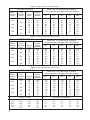
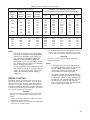
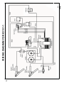
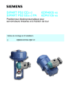
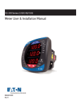
1
IM10130 Manual Wheel Charger For use with machines having Code Numbers: September, 2012 (See Below) Safety Depends on You Century charging equipment is designed and built with safety in mind. However, your overall safety can be increased by proper installation ... and thoughtful operation on your part. DO NOT INSTALL, OPERATE OR REPAIR THIS EQUIPMENT WITHOUT READING THIS MANUAL AND THE SAFETY PRECAUTIONS CONTAINED THROUGHOUT. And, most importantly, think before you act and be careful. K3151-1 (11862) 60/40/30/225, 6/12 /24V K3150-1 (11861) 60/40/2/250, 6/12V W/ TEST K3149-1 (11860) 40/20/2/200, 6/12V W/ TEST OPERATOR’S MANUAL Century Equipment 2345 Murphy Blvd. Gainesville, GA 30504 TABLE OF CONTENTS ENGLISH SAFETY SUMMARY ....................................3 SAFETY INFORMATION ........................3 SHOCK HAZARDS ............................3 EXPLOSIVE GAS HAZARDS ............3 BATTERY EXPLOSION HAZARDS ..4 FIRE HAZARDS ................................4 BATTERY ACID HAZARDS................4 MOVING PARTS HAZARDS ..............4 BURN HAZARDS ..............................4 INTRODUCTION ..........................................5 DESCRIPTION ........................................5 HOW BATTERIES CHARGE ..................5 SPARK PREVENTION ............................5 DEEPLY-DISCHARGED LEAD-CALCIUM BATTERIES ............5 ASSEMBLY ..................................................6 ASSEMBLY INSTRUCTIONS..................6 PREPARATION ............................................7 CHARGER PREPARATION ....................7 CHARGER PLACEMENT ..................7 PROVIDE REQUIRED POWER ..............7 EXTENSION CORDS ........................7 BATTERY PREPARATION ......................7 CONTROLS AND INDICATORS ..................8 CONTROL SETTING INSTRUCTIONS ..8 CHARGE VOLTAGE AND RATE SELECTION ............................8 TIMER SWITCH SETTING ................8 VOLTMETER/TEST METER TESTING ............................................8 BATTERY PERCENT OF CHARGE TEST (12 VOLT ONLY) ......................9 ALTERNATOR TEST (12 VOLT ONLY) ..............................9 PRE-CHARGE BATTERY ACTIVATION ......................................9 OPERATION ..............................................10 OPERATING INSTRUCTIONS ..............10 CONNECTING TO BATTERIES INSTALLED IN VEHICLES ..............10 CONNECTING TO BATTERIES OUTSIDE A VEHICLE ..........................10 CHARGING INSTRUCTIONS................11 READING AN AMMETER......................11 CHARGING TIME INSTRUCTIONS .12,13 2 ENGINE STARTING ..............................14 MAINTENANCE..........................................15 TROUBLESHOOTING ..........................15 WIRE DIAGRAM.S.................................16, 17 PARTS PAGES ......................P-712 SERIES SAFETY SUMMARY Congratulations on the purchase of your new battery charger. We wish to acknowledge Underwriters Laboratories (U/L) for contributing the following important safety precautions. Please read and retain these instructions for the continued safe use of your new charger. This manual contains important safety information. DO NOT OPERATE this equipment UNTIL YOU HAVE READ this safety summary! IMPORTANT SAFETY INSTRUCTIONS. SAVE THESE INSTRUCTIONS SAFETY INFORMATION The following safety information is provided as guidelines to help you operate your new battery charger under the safest possible conditions. Any equipment that uses electrical power can be potentially dangerous to use when safety or safe handling instructions are not known or not followed. The following safety information is provided to give the user the information necessary for safe use and operation. 11. ALWAYS plug in and unplug the ac power cord by grasping the power cord plug, NOT THE POWER CORD, to reduce risk of damaging power cord. 12. ALWAYS remove personal metal items such as rings, bracelets, and watches when working with a lead-acid battery. A lead-acid battery can produce a short circuit current high enough to weld a ring or any jewelry to metal causing a severe burn. 13. ALWAYS unplug the battery charger from the ac outlet before attempting any cleaning or maintenance. Turning the charger’s control(s) OFF, alone, will not remove all electricity from the charger. 14. An extension cord should not be used unless absolutely necessary. Use of an improper extension cord could result in a fire or electric shock. If an extension cord must be used, make sure that: a. the pins on the plug of the extension cord are the same number, size, and shape as those of the plug on the charger, A procedure step preceded by WARNING is an indication that the next step contains a procedure that might be injurious to a person if proper safety precautions are not heeded. b. the extension cord is properly wired and in good electrical condition, and c. the wire size is large enough for the length of cord as specified in the following chart. A procedure preceded by a CAUTION is an indication that the next step contains a procedure that might damage the equipment being used. A NOTE may be used before or after a procedure step to highlight or explain something in that step. Length in feet: 25 50 100 150 cord AWG size: 16 12 10 8 SHOCK HAZARDS EXPLOSIVE GAS HAZARDS 1. This battery charger is intended for indoor use only. Do not expose the charger to rain or snow. 2. NEVER attempt to charge a marine (boat) battery while the boat is on or near the water. A boat must be on a trailer and located indoors before attempting to charge its battery(s). The boat manufacturer’s battery charging instructions must be followed exactly. 3. NEVER set the charger, output cable or clamps, or ac power cord plug in water or on wet surfaces. 4. NEVER use this charger on a pier or dock. Charger could fall in water, creating an electric shock hazard. 5. NEVER attempt to plug in or operate the battery charger with defective or damaged wires, power cord, or power cord plug. Have any of these parts that are defective or damaged replaced by qualified personnel IMMEDIATELY. 6. NEVER attempt to plug in the charger or operate its controls with wet hands or while standing in water. 7. NEVER alter the ac power cord or power cord plug provided with the battery charger. 8. NEVER use an attachment not recommended or sold by the battery charger manufacturer for use with this specific model battery charger 9. NEVER operate this battery charger if it has received a sharp blow, been dropped, or similarly damaged, until after being inspected and/or repaired by qualified service personnel. 10. NEVER disassemble this battery charger. Take the battery charger to qualified service personnel when service or repair is needed. 3 1. 2. 3. 4. Working in the vicinity of a lead-acid battery is dangerous. Batteries generate explosive gasses during normal operations and, at an even higher level, during charging. If anything is allowed to ignite these gasses, the battery may explode, sending pieces of the battery and extremely caustic battery acid out in all directions and with extreme force. Since just the slightest spark is sufficient to ignite these gasses, it is of UTMOST IMPORTANCE that you read this manual and follow the instructions exactly, before using your battery charger each time. NEVER operate this battery charger near any fuel tanks or gas cylinders. This charger can produce sparks that could ignite gasses and cause an explosion. NEVER attempt to permanently mount this battery charger on a marine or recreational vehicle. NEVER attempt to connect this charger’s output cables directly to the battery(s) in the bilge or engine compartment of a boat. Follow the boat manufacturer’s battery charging instructions exactly. FIRE HAZARDS BATTERY EXPLOSION HAZARDS 1. 2. 3. 4. 5. 6. 7. 8. 9. 10. 11. 12. 13. 14. To reduce the risk of battery explosion, read, understand, and follow these instructions, those published by the battery manufacturer, and those of the manufacturer of any equipment you intend to use near the battery. Review cautionary markings on these products and on the engine. If unable to determine the battery manufacturer’s requirements for charging, always charge the battery with the cell caps in place. In addition, make certain that anyone else that uses this equipment, or is a bystander in the vicinity of a charging battery, understands and follows these safety instructions as well. NEVER smoke or allow a spark or flame in the vicinity of the battery or engine. NEVER operate the battery charger in a closed-in area or restrict ventilation in any way. NEVER charge a frozen battery as battery explosion can result. NEVER connect BOTH battery charger clamps DIRECTLY to the two posts of the same battery. See OPERATION INSTRUCTIONS for connection procedures. NEVER charge batteries other than a LEAD-ACID type. Especially, DO NOT use for charging dry-cell batteries that are commonly used with toys and home appliances. These batteries may burst and cause injury to persons or damage property. NEVER allow the dc output clamps to touch each other. ALWAYS be extra cautious to reduce the risk of dropping a metal object, such as a tool, onto or near the battery. Doing so could produce a spark or short circuit the battery or other electrical part that could cause an explosion. ALWAYS make sure the area around a battery is well ventilated while it is being charged. Gas can be forcefully blown away by using a piece of cardboard or other non-metallic material as a fan. ALWAYS make sure that the ac power cord is unplugged from the ac outlet or extension cord BEFORE connecting or disconnecting the battery charger clamps, to prevent arcing or burning. ALWAYS locate the battery charger as far away from the battery as the dc output cables will permit. ALWAYS twist or rock charger clamps back and forth several times on the battery post and the other point of connection at the time of initial connection. This helps keep the clamps from slipping off their points of connection which helps reduce the risk of sparking. DO NOT rock the clamp connected to the battery post AFTER the second connection (at a point away from the battery) is made or sparking may occur at the battery post. ALWAYS check the cable and wire connections at the battery(s) for tightness - BEFORE STARTING TO CHARGE. A loose connection can cause sparks or excessive heating which could cause a battery explosion. ALWAYS make sure the battery compartment is open and well ventilated before charging. 1. 2. 3. NEVER use an attachment not recommended or sold by the battery charger manufacturer for use with your specific model charger. NEVER disassemble the battery charger; take it to qualified service personnel when service or repair is needed. ALWAYS make sure that the ac power cord is unplugged from the ac outlet or extension cord, BEFORE connecting or disconnecting the battery charger clamps, to prevent arcing or burning. BATTERY ACID HAZARDS 1. 2. 3. 4. ALWAYS have someone within range of your voice and close enough to quickly come to your aid when working near a lead-acid battery. ALWAYS have plenty of fresh water and soap nearby in case battery acid contacts eyes, skin, or clothing. ALWAYS wear complete eye and clothing protection and avoid touching eyes while working with a battery. ALWAYS act QUICKLY if contact with battery acid is made. If acid contacts skin or clothing, wash IMMEDIATELY with soap and water. If acid enters the eye, IMMEDIATELY flood the eye with running cold water for at least 10 minutes. Get medical attention IMMEDIATELY. MOVING PARTS HAZARDS 1. 2. 3. NEVER connect the battery charger clamps to a vehicle when the engine is running. ALWAYS stay clear of fan blades, fan belts, pulleys and other moving engine parts when working near an engine. Moving engine parts can cause severe personal injury including dismemberment. ALWAYS make sure that the battery charger cables and clamps are positioned so they will not come in contact with any moving engine parts. BURN HAZARDS 1. 2. NEVER lean on or rest against the engine or cooling system parts when the vehicle is running. ALWAYS stay clear of the cooling system, engine, and engine manifold. These engine components get very hot and retain heat for a long time. Touching any of these components can cause severe burns. 4 INTRODUCTION DESCRIPTION This battery charger is designed to handle the majority of your charging and starting needs. NOTE: A slow bubbling sound may be heard coming from the battery during the charging process. This is a normal condition and just another indicator the battery is being charged. MULTIPLE CHARGE RATES for various battery sizes. High-AMPERAGE ENGINE START to help start vehicles when the battery is too weak to do the job alone. An AMMETER to monitor charging progress SPARK PREVENTION A TIMER switch to set the desired charge time. LARGE SAW-TOOTH CLAMPS assure good connection to top or side-mount battery terminals. WHEEL AND HANDLE KIT for easy moving around your shop. MAKE SURE no sparks or flames occur near the battery, especially during charging. It takes very little to ignite the explosive gasses produced by a lead-acid battery. Read, understand, and follow the safety information provided in the SAFETY SUMMARY section of this manual before attempting to work with or near a lead-acid battery. HEAVY-DUTY CONSTRUCTION for long, trouble-free life. To reduce the risk of battery overcharging, it is important to thoroughly read this instruction manual. For more information about batteries and battery charging, contact Battery Council International at (312) 644-6610, and request their BATTERY SERVICE MANUAL, which is available for a nominal charge. HOW BATTERIES CHARGE A charger DOES NOT FORCE current into a battery - it makes a limited amount of current available and the battery draws as much of it as it needs, up to or slightly greater than the rated output current capability of the charger. The closer a battery is to zero charge (dead battery), the more charging current it will want to draw. When charging begins, on a dead battery, the chargers ammeter will register toward the high end of the ammeter scale and move toward zero as the battery becomes more fully charged. KEEP IN MIND, the ammeter registers the amount of amperage being drawn from the charger by the battery, not what the charger is capable of delivering. One would expect a battery to draw zero amps when it reaches 100% charge. But at 100% charge, the battery will continue to draw a low level of current and convert it into heat within the battery. If left connected and charging after reaching 100% charge, the battery acid will begin to boil, resulting in overcharging and possible battery damage. 5 DEEPLY-DISCHARGED LEAD-CALCIUM BATTERIES Many newer automotive batteries are of a lead-calcium plate design. When deeply discharged, they may require an activation period before accepting a measurable charge. This activation period may take as long as 4 to 8 hours. If, at the beginning of the charging process, you notice that the ammeter (if so equipped) is at or near zero, but you have determined that the battery is very discharged (less than 25% of charge), this is a good indication that an activation period is required (see PRE-CHARGE BATTERY ACTIVATION). ASSEMBLY ASSEMBLY OF HANDLE AND CLAMP HOLDER Assemble the charger handle and clamp holder according to the following instructions and illustrations. FIGURE 3 REPLACE TOP 2 SCREWS THEN TIGHTEN ALL 4 SCREWS 1. Carefully remove the charger unit and all associated hardware from carton, note the charger is shipped with the handle partially secured, and resting in a down position on the front of the unit. 2. Unscrew the top 2 screws on either side of the charger. Remove the bottom 2 screws holding handle with the washers (washers will be discarded), as shown in Figure 1 . 5. Carefully screw the clamp holder together onto the handle as shown in Figure 4. FIGURE 1 FIGURE 4 REMOVE AND DISCARD 2 WASHERS TOP 2 SCREWS CLAMP HOLDER BOTTOM 2 SCREWS HANDLE HANDLE 3. Then replace the bottom 2 screws by screwing in part way so the handle can be move to an upright position. (See Figure 2) SCREWS FIGURE 2 REPLACE BOTT OM 2 SCREWS BY SCREWING IN PART WAY ROTATE HANDLE TO UPRIGHT POSITION 4. Align the holes of the handle with the top 2 screw holes of the charger. Replace the top 2 screws which you removed in Figure1. Tighten all 4 screws securing the handle in the upright position. (See Figure 3) 6 PREPARATION CHARGER PREPARATION CHARGER PLACEMENT WARNING Place the charger in a clean, dry, stable, well-ventilated spot as far away from the battery as the dc output cables permit. NEVER place the charger directly above the battery being charged; gasses from the battery will corrode and damage the charger. NEVER allow battery acid to drip on the charger when reading specific gravity or filling the battery. NEVER set a battery on top of the charger. NEVER attempt to permanently mount this battery charger on a marine or recreational vehicle. ALWAYS position the charger on the outside of a boat or recreational vehicle. PROVIDE REQUIRED POWER This battery charger requires a nominal 120 volt, 60 Hertz, alternating current (ac) power source. The power source must be fused at an amperage greater than or equal to the INPUT AMPS rating of this charger. DO NOT PLUG THE CHARGER INTO THE AC POWER SOURCE UNTIL TOLD TO DO SO IN THE OPERATING INSTRUCTIONS. WARNING ELECTRIC SHOCK CAN KILL! To reduce risk of electric shock, never alter ac power cord or power cord plug provided on the charger. If it will not fit the outlet, have a proper outlet installed by a qualified electrician. Never use an adapter The charger must be grounded to reduce risk of electric shock. The charger is equipped with an electric cord that has an equipment grounding plug. The plug must be plugged into an outlet that is properly installed and grounded in accordance with all local codes and ordinances. FIRE CAN KILL, INJURE, AND CAUSE PROPERTY DAMAGE! To reduce risk of electric shock and fire, never alter the ac power cord or power cord plug provided on the charger. Never alter extension cords or extension cord plugs. Make sure the extension cord is properly wired and in good electrical condition. Make sure the wire size (American Wire Gauge or AWG) of the extension cord is large enough to handle your specific charger’s amperage requirements. BATTERY PREPARATION WARNING BATTERY EXPLOSION CAN INJURE, AND CAUSE PROPERTY DAMAGE! NEVER SMOKE OR ALLOW A SPARK OR FLAME IN THE VICINITY OF THE BATTERY OR ENGINE. If it is necessary to remove the battery from the vehicle to charge it, make sure all accessories in the vehicle are off and ALWAYS remove the grounded cable from the battery FIRST. If needed, add distilled water to each cell of the battery until battery acid reaches the manufacturer’s specified level. DO NOT OVERFILL. This helps remove excessive explosive gasses from the battery. For maintenance free batteries without caps, carefully follow the battery manufacturer’s recharging instructions. WARNING EXTENSION CORDS An extension cord should not be used unless absolutely necessary. If necessary, care must be taken to select an extension cord suitable for use with your specific battery charger (see SHOCK HAZARDS in SAFETY SUMMARY). NOTE: Engine starting performance may be reduced when extension cords are used. BATTERY ACID CAN CAUSE SERIOUS INJURY AND PROPERTY DAMAGE! Always wear complete eye and clothing protection and avoid touching eyes while working near battery. Clean battery terminals. Be careful to keep corrosion from coming in contact with eyes. Study all of the battery manufacturer’s precautions, such as whether cell caps should be left in place or removed during charging, and the recommended rates of charge for the specific battery. If you are unable to determine the battery manufacturer’s requirements for charging, always charge the battery with the cell caps in place. If the battery voltage cannot be determined from the information on the battery itself, refer to the owner’s manual for the product in which the battery was installed. 7 CONTROLS AND INDICATORS CHARGE RATE SELECTOR switch is a multi position rotary switch. The available settings, for each charger are shown in Figure 5. FIGURE 5. Charge Rate Selector Switch Settings 200A 12V START 130A 12V START 40A 12V OFF 20A 12V 40A 6V 2A 12V 40 amp model 250A 12V START 185A 6V START 60A 12V OFF 40A 12V 60A 6V 2A 12V 60 amp model 30A 24V 225A 12V START 60A 12V OFF 60A 6V 160A 6V START 40A 12V OFF 24V Fleet model TIMER switch allows the selection of any charging time, up to 120 minutes. When the selected time is up, the timer automatically shuts AMMETER indicates the charging current being drawn from the charger by the battery. See READING AN AMMETER in this manual. VOLTMETER the voltmeter will indicate voltage whenever the charger is turned on, or when the clamps are connected to a battery. If connected to a battery, and the unit is turned on, it will read the combined voltage of the battery and the charger. If there is no reading when connected to a battery, check the connections and/or the battery. CONTROL SETTING INSTRUCTIONS CHARGE VOLTAGE AND RATE SELECTION ( See Figure 6 and 7) Set the RATE SELECTOR to the same voltage and charge rate that is appropriate for the size and type of battery being charged. Use the battery manufacturer’s instructions or see the guidelines below. If the battery voltage is not clearly marked on the battery, refer to the operator’s manual for the vehicle/ equipment where the battery is used / intended to be used. Do not begin charging if the battery voltage cannot be determined. The available settings are in Table 1. t Small Motorcycle type 3 Amps or less t Lawn mower/Tractor 6 Amps or less t Deep-cycle 25 Amps or less t Maintenance-free Auto or Marine Cranking 45 Amps or less t Heavy-duty Commercial 60 Amps or less Unless the information is supplied for the particular battery, always charge small 12-volt batteries at no more than 2amps. Not all of these chargers are capable of charging at 2 amps or less. If your charger is one of those, do not attempt to charge the small 12 volt batteries on that charger. Charge only standard sized 6 and 12 volt automobile batteries on those chargers. NOTE: The charger ammeter will not taper on 6 volt settings. Use charging time equations or charts only to determine the time needed to fully charge the battery. TIMER SWITCH SETTING (See Figure 6 and 7) Set the timer for the length of charging time required to bring the battery to full charge, as determined in CHARGING TIME INSTRUCTIONS. When selecting times less than 20 minutes, turn timer past the 20 - minute mark, then back to the time desired. Setting the time to charge starts the charging process. To prevent overcharging, do not set the timer for more time than it will take to bring the battery to full charge. If the timer is turned to the left , past OFF, HOLD is selected. In this position, the charger will ly. This position should be used only remain ON inde when charging at a low rate for extended periods. The battery can be damaged when being charged for extended periods, especially at higher amperages. VOLTMETER/TEST METER TESTING (See Figure 7) The VOLTMETER/TEST METER, available in some models, allows additional testing to be performed. In normal operation, without the TEST SWITCH pressed, the meter reads from 0-20 volts dc (0 and 20 are not actually seen on the meter face but are represented by the ends of the scale), on the lower scale of the meter. Using this part of the meter, during charging, the voltage should read: t t for 6 volt batteries read 6.5 to 8.5 volts for 12 volt batteries read 13.5 to 16.5 volts 8 If the voltmeter reads outside these voltages, refer to the chart below for possible battery conditions: VOLTS LOW, AMPS HIGH Probable shorted Battery — replace. VOLTS LOW, AMPS LOW Poor Connection or Frozen Battery VOLTS HIGH, AMPS LOW Battery Cold or Sulfated — Reduce charge rate and charge longer. After charging is complete, the voltmeter should read the full charge voltage of the battery. This is normally higher than the rated battery voltage. To perform testing functions, press the TEST SWITCH and read the top scale on the meter. NOTE: This type of repair work is rather specialized. It may require additional tests using other instruments for complete diagnosis. REMEMBER: The charger must be turned OFF to perform the tests. If attempting to test with the charger turned ON, the results will be meaningless. Battery percent of charge test (12 volt only) 1. 2. PRE-CHARGE BATTERY ACTIVATION Some modern batteries can cause charging problems if they have been deeply discharged. The plates in these batteries can begin sulfating quickly, forming a barrier to accepting a charge. This condition will be indicated by an extremely low (or zero) ammeter reading. A deeply discharged battery such as this may take as long as 4 to 8 hours before it will accept a charge. When charging a battery with this condition, set the RATE SELECTOR for a moderate charge rate and check on the battery every 30 minutes. When the sulfate barrier has been broken through, the battery will begin accepting a charge and the ammeter will register a higher, normal charging rate. The amount of time to charge the battery fully (determined in CHARGING TIME INSTRUCTIONS) begins when the battery begins accepting a charge. If necessary, reset the timer (if your charger is so equipped) to the length of charging time required, after the battery begins accepting a charge. FIGURE 7 CHARGE VOLTAGE AND RATE SELECTION AMMETER With the charger OFF and clamps properly connected to the battery, press the TEST SWITCH and read the battery percent of charge on the top left scale of the test meter. If the battery has been recently charged or is in a vehicle that has been run recently, there is probably a surface charge on the battery. This will give a falsely high reading on the percent of charge test. Remove the SURFACE CHARGE by turning on the vehicle headlights for TEST three or more minutes. Allow the battery to sit for one SWITCH minute. Retest the battery percent of charge. Alternator test (12 volt only) 1. 2. 3. OK Charging system is performing properly LOW Loose fan belt, or voltage regulator and/or alternator faulty HIGH Faulty voltage regulator or wiring harness DC VOLTMETER 40 AMP AMD 60 AMP MODELS With the charger OFF and clamps properly hooked to the battery, start the engine and while running at fast idle, press the TEST SWITCH. Read the alternator condition on the alternator test scale at the upper right section of the test meter. The battery should be in a good state of charge before attempting this test. The three zones of the meter indicate the following: TIMER SWITCH SETTINGS FIGURE 8 CHARGE VOLTAGE AND RATE SELECTION TIMER SWITCH SETTINGS FIGURE 6 AMMETER VOLTS 24V FLEET MODEL Voltmeter / Test Meter 9 OPERATION OPERATING INSTRUCTIONS 1) Connect the POSITIVE (red) clamp from the battery charger to the POSITIVE, ungrounded terminal of the battery. 2) Connect the NEGATIVE (black) clamp from the battery charger to a heavy gauge metal part of the vehicle chassis or engine block away from the battery. DO NOT connect the NEGATIVE (N) (black) charger clamp to the NEGATIVE battery terminal, carburetor, fuel lines, or sheet metal body parts. ATTENTION! DO NOT ATTEMPT TO OPERATE THIS BATTERY CHARGER until you have read and understood the entire SAFETY SUMMARY provided in this manual. NOTE: Go to ASSEMBLY in this manual before proceeding with the operation of your battery charger. DO NOT ATTEMPT TO OPERATE THE CHARGER UNTIL ALL REQUIRED USER-ASSEMBLY IS COMPLETED. b. Positive ground vehicles (see Figure 10) Positive to Chassis Ground CONNECTING TO BATTERIES INSTALLED IN VEHICLES ATTENTION Do not plug the charger power cord into the ac power source or set any of the charger’s controls until told to do so in the following instructions. 1. 2. 3. 4. Make sure that the ac power cord is unplugged from the ac outlet and make sure the vehicle’s engine is turned off. Position the ac power cord and dc output cables in such a manner that they cannot be damaged by moving engine parts or the vehicle’s hood or doors. Check the polarity of the battery terminals. The POSITIVE terminal should be marked: POSITIVE, POS, +, or P. The NEGATIVE terminal should be marked: NEGATIVE, NEG, –, or N. Determine whether the vehicle has a positive or negative grounded battery (positive or negative cable is connected to the vehicle’s chassis). Negative Figure 10. Positive Ground 1) Connect the NEGATIVE (black) charger clamp to the NEGATIVE, ungrounded terminal of the battery. 2) Connect the POSITIVE (red) charger clamp to a heavy gauge metal part of the vehicle chassis or engine block away from the battery. DO NOT connect the POSITIVE (red) charger clamp to the POSITIVE battery terminal, carburetor, fuel lines, or sheet metal body parts. WARNING MOVING ENGINE PARTS CAN CAUSE SERIOUS INJURY! Stay clear of fan blades, belts, pulleys, and other moving engine parts to reduce risk of serious personal injury. a. Negative ground vehicles (The most common type, see Figure 9). Negative to Chassis Ground CONNECTING TO BATTERIES OUTSIDE A VEHICLE 1. 2. Make sure that the ac power cord is unplugged from the ac power source. Check the polarity of the battery terminals (see Figure 11). The POSITIVE terminal should be marked: POSITIVE, POS, +, or P. The NEGATIVE terminal should be marked: NEGATIVE, NEG, –, or N. Booster Cable Negative (–) Charger Cable From Charger Positive (+) Charger Cable Positive Figure 11. Connecting Outside The Vehicle Figure 9. Negative Ground 10 3. Attach a battery or booster cable, AT LEAST 24 inches long that is the same (or larger) wire gauge as the charger cable, to the NEGATIVE terminal of the battery. WARNING BATTERY EXPLOSION CAN INJURE, AND CAUSE PROPERTY DAMAGE! To reduce the risk of battery explosion, NEVER CONNECT BOTH BATTERY CHARGER CLAMPS DIRECTLY TO THE TWO POSTS OF A BATTERY. 4. 5. Connect the POSITIVE (red) charger clamp to the POSITIVE battery terminal. Position yourself and the free end of the cable (attached to the NEGATIVE battery terminal) as far away from the battery as the cable will allow. Then, WHILE FACING AWAY FROM THE BATTERY, connect the NEGATIVE charger clamp to the free end of the cable. CHARGING INSTRUCTIONS 1. 2. 3. 4. Determine the length of time necessary to charge the battery in CHARGING TIME INSTRUCTIONS, but do not start the timer. Set all switches and the timer to OFF and connect the charger power cord into an appropriate ac outlet. Set charging voltage, charging rate, and any other functions according to CONTROL SETTING INSTRUCTIONS. On models so equipped, set the TIMER for the desired length of charge time. WARNING BATTERY EXPLOSION CAN INJURE, AND CAUSE PROPERTY DAMAGE! To reduce risk of battery explosion, do not overcharge a lead-acid battery. Follow disconnection procedure EXACTLY. 5. 6. When charging is complete, turn all charger controls to OFF. Then unplug the charger’s ac power cord from the ac power source. Disconnect the charger clamp NOT attached directly to the battery first and DO NOT allow the clamp to touch anything. Then, disconnect the charger clamp attached to the battery terminal. READING AN AMMETER The ammeter indicates the charging current being drawn from the charger by the battery. As the battery becomes more fully charged, the charge rate lessens and the ammeter needle moves toward the lower amp numbers on the meter. During engine starting, the ammeter will usually peg to the high-amperage end of the meter. There is no clear-cut way to read an ammeter and determine exactly when charging is complete (if the charger is so equipped, a green light on the charger indicates battery is 11 fully charged). At full charge, the ammeter will still register some current draw (approximately 50% of the charger’s output rating). In many cases, overcharging can occur if the charger is not disconnected when the battery reaches full charge - or sooner. Therefore, it is very important that you follow the CHARGING TIME INSTRUCTIONS provided in this manual. Several battery conditions can also cause the ammeter to appear to indicate a battery near full charge, when in fact, charging has only begun. Cold Battery Sulfated Battery Deeply-Discharged, Lead-Calcium Battery (many newer automotive batteries) WARNING BATTERY EXPLOSION CAN INJURE, AND CAUSE PROPERTY DAMAGE! To reduce risk of battery explosion, check to make sure a cold battery is not frozen. Battery explosion can result from attempting to charge a frozen battery. COLD BATTERIES (temperatures lower than 32° F or 0° C) will begin charging at a low rate of charge. But as the battery warms up through charging, the charge rate will increase. Then, as the battery charges up, the charge rate will decrease normally. SULFATED or DEEPLY-DISCHARGED LEAD-CALCIUM BATTERIES - require a special activation procedure. See DEEPLY DISCHARGED LEAD-CALCIUM BATTERIES in CHARGING TIME INSTRUCTIONS. SHORTED BATTERIES - When the battery being charged has a short circuit, the ammeter will peg at the high-amp end of the scale. If after 5 to 10 minutes of charging, the needle has not started to move toward lower amperages, unplug the charger and discontinue charging. If available, use a voltmeter and read the battery voltage. If the voltage is LESS THAN 12.0 volts for a 12 volt battery or LESS THAN 6.0 volts for a 6 volt battery, plug the charger back in and resume charging. If after another 15 to 20 minutes, the ammeter has failed to move toward lower amperages, repeat the voltmeter test. If the voltage has not increased, the battery needs to be serviced or replaced. CAUTION DO NOT USE AMMETER to determine when full charge is reached. Failure to comply with this caution could cause the battery to be damaged from overcharging. The battery could overheat and even explode. CHARGING TIME INSTRUCTIONS Manual battery chargers need to be disconnected from a battery when the battery has reached 100% of charge OR SOONER. If this is not done, the battery will overcharge, resulting in possible battery damage. The following instructions or the associated LENGTH OF CHARGE TIME CHARTS (60 amps down to 2 amps, one for each charging range) will allow you to determine how long it will take to bring a spec battery to full charge. If the charger is so equipped, a green light on the charger will indicate the battery has become fully charged. EXAMPLE: Battery’s Present State of Charge: 25% Percent of Charge NEEDED: 100% – 25% = 75% Expressed as a Decimal: = .75 Amp setting on Charger: 10 Amp-Hour Rating of Battery: 60 CAUTION Batteries that have 25% charge or less can easily freeze and should be charged at once, but DO NOT CHARGE A BATTERY THAT IS ALREADY FROZEN. 1. 2. 3. Determine the present level of charge in the battery with a hydrometer or electronic percent-of-charge tester. Determine the size of the battery in AMP HOURS or RESERVE CAPACITY. If these ratings are not printed on the battery, contact your local battery dealer for this information. These are the only ratings that can be used to determine length of charging time. Then either use the formula in step 3 or use Table 2 plus Table 3, through Table 9 for the charging rate capabilities of this charger. Use the battery rating, the charge level of the battery, and the amp setting to be used on the charger (see Table 2), in the formula provided below. X Model 6V HIGH 1.25 = 60 X .75 10 X 1.25 = Hours to Reach Full Charge 45 10 X 1.25 = Hours to Reach Full Charge 4.5 X 1.25 = Hours to Reach Full Charge NOTE : If the battery is rate d in RESERVE CAPACITY, use the following formula to convert reserve capacity to amp-hours. Reserve Capacity 2 + 15.5 = Amp Hour Rating Hours to Charge Table 2. Charge Amp Settings 12V LOW 12V MED . 12V HIGH K3149-1 40 Amp 2 Amp 20 Amp 40 Amp K3150-1 60 Amp 2 Amp 40 Amp 60 Amp K3151-1 60 Amp 40 Amp 60 Amp 24V HIGH 30 Amp START 200 Amp 12V 130 Amp 6V 250 Amp 12V 185 Amp 6V 225 Amp 12V 160 Amp 6V 12 Table 3. Length of Charge Time Chart 60 Amps BATTERY RATINGS Approx. Marine Cranking Amps Approx. Cold Cranking Amps 750 600 550 500 400 400 300 300 200 MINUTES TO CHARGE @ 60 AMPS for the percent-of-charge now in the battery Ampere Hours Reserve Capacity (Minutes) 0% 25% 50% 75% 100% 66 61 56 51 46 41 36 31 26 100 90 80 70 60 50 40 30 20 83 76 70 64 58 51 45 39 33 62 57 53 48 43 38 34 29 24 41 38 35 32 29 26 23 19 16 21 19 18 16 14 13 11 10 8 0.0 0.0 0.0 0.0 0.0 0.0 0.0 0.0 0.0 Table 4. Length of Charge Time Chart 40 Amps BATTERY RATINGS Approx. Marine Cranking Amps Approx. Cold Cranking Amps 750 600 550 500 400 400 300 300 200 Ampere Hours 66 61 56 51 46 41 36 31 26 Reserve Capacity (Minutes) 100 90 80 70 60 50 40 30 20 MINUTES TO CHARGE @ 40 AMPS for the percent-of-charge now in the battery 0% 25% 50% 75% 100% 124 114 105 96 86 77 68 58 49 93 86 79 72 65 58 51 44 37 62 57 53 48 43 38 34 29 24 31 29 26 24 22 19 17 15 12 0.0 0.0 0.0 0.0 0.0 0.0 0.0 0.0 0.0 Table 5. Length of Charge Time Chart 20 Amps BATTERY RATINGS Approx. Marine Cranking Amps Approx. Cold Cranking Amps 750 600 550 500 400 400 300 300 200 Ampere Hours 66 61 56 51 46 41 36 31 26 Reserve Capacity (Minutes) 100 90 80 70 60 50 40 30 20 MINUTES TO CHARGE @ 20 AMPS for the percent-of-charge now in the battery 0% 25% 50% 75% 100% 248 229 210 191 173 154 135 116 98 186 172 158 144 130 116 102 88 74 124 114 106 96 86 76 68 58 48 62 58 52 48 44 38 34 30 24 0.0 0.0 0.0 0.0 0.0 0.0 0.0 0.0 0.0 HOURS TO CHARGE DEEP CYCLE* N/A N/A N/A N/A N/A 13 N/A N/A N/A N/A N/A 135 110 100 90 80 N/A N/A N/A N/A N/A 8.4 6.9 6.2 5.6 5.0 8.4 6.9 6.3 5.6 5.1 5.6 4.5 4.1 3.7 3.3 2.8 2.3 2.1 1.9 1.7 0.0 0.0 0.0 0.0 0.0 Table 6. Length of Charge Time Chart 2 Amps BATTERY RATINGS Approx. Marine Cranking Amps Approx. Cold Cranking Amps 750 600 550 500 400 400 300 300 200 Ampere Hours 66 61 56 51 46 41 36 31 26 Reserve Capacity (Minutes) 100 90 80 70 60 50 40 30 20 HOURS TO CHARGE @ 2 AMPS for the percent-of-charge now in the battery 0% 25% 50% 75% 100% 41.3 38.1 35.0 31.9 28.8 25.6 22.5 19.4 16.3 30.9 28.6 26.3 23.9 21.6 19.2 16.9 14.5 12.2 20.6 19.1 17.5 15.9 14.4 12.8 11.3 9.7 8.1 10.3 9.5 8.8 8.0 7.2 6.4 5.6 4.8 4.1 0.0 0.0 0.0 0.0 0.0 0.0 0.0 0.0 0.0 HOURS TO CHARGE DEEP CYCLE* N/A N/A N/A N/A N/A 135 110 100 90 80 N/A N/A N/A N/A N/A N/A N/A N/A N/A N/A NOTE: The length of charge times on these charts are very accurate when using the RESERVE CAPACITY or AMPERE HOUR battery ratings. The COLD CRANKING AMPS and MARINE CRANKING AMPS ratings are approximations and vary from battery to battery. Always follow the battery manufacturer·s specific charging instructions. Do not charge deep cycle batteries with a battery charger, or setting on a charger, that has a rating of more than 25 amps. Follow the battery manufacturer·s specific charging instructions. ENGINE STARTING This battery charger can provide a high-current output to help start a vehicle with a weak battery. However, the onboard computer in some vehicles can be damaged when attempting to jump start. ALWAYS READ THE VEHICLE OPERAT25·6 MANUAL BEFORE AUXILIARY STARTING to determine if jump starting can do damage to the vehicle. If not, read and follow these instructions. 84.4 68.8 62.5 56.3 50.0 3. 63.3 51.6 46.9 42.2 37.5 42.2 34.4 31.3 28.1 25.0 21.1 17.2 15.6 14.1 12.5 0.0 0.0 0.0 0.0 0.0 Set the RATE SELECTOR to START and try to start the vehicle. If the vehicle GRHVQ·t start after 3 to 4 seconds, stop and wait 3 to 4 minutes. Repeat until engine starts. CAUTION Excessive continuous engine cranking can damage vehicle starter motors. NOTE: If the engine spins but fails to start after several starting attempts there is an engine problem not related to the starting system. Discontinue cranking the engine until the other problem is found and corrected. This battery charger has an internal thermal protector to prevent overheating and damage to the battery charger. If, after repeated starting attempts, the ammeter registers zero output, wait 3 to 4 minutes for the charger to cool. The thermal protector will automatically reset and allow you to continue. CAUTION Do not try to boost start a vehicle that does not contain a battery or you may damage electrical system in the vehicle. 1. 2. Connect the battery charger to the vehicle according to OPERATING INSTRUCTIONS. Charge the battery for 5 to 10 minutes at the appropriate charge rate for the size of battery. 14 MAINTENANCE CAUTION Make sure charger is unplugged from ac outlet before performing any cleaning or maintenance. A minimum amount of care can keep your battery charger working and looking good for years. 1. 2. 3. Clean the clamps after each use. Wipe off any battery fluid that may have come in contact with the clamps to prevent corrosion. Battery fluid may be neutralized with a solution of water and baking soda. Coil the input and output cables neatly after each use. This will help prevent damage to the cables and the charger. If needed, the case may be wiped clean with a soft cloth. TROUBLESHOOTING 1. No Ammeter Reading (Battery does not accept charge). a. Make sure charger is plugged into live ac outlet. b. After unplugging unit, check connection at battery. Make sure the clamps are making good contact with the battery terminal (or vehicle chassis). c. Check to see that the battery is capable of being charged. It may be damaged or sulfated. d. Make sure that you have selected the proper charge voltage for the battery being charged. 2. 15 e. Make sure you are allowing enough time for charging the battery. Refer to the charging time formulas earlier in this manual. Ammeter shows reading, but battery does not accept charge. 3. a. Check to see that the battery is capable of being charged. It may be damaged or sulfated. b. Make sure you are allowing enough time for charging the battery. Refer to the charging time formulas earlier in this manual. Vehicle will not start in engine start mode a. Unplug charger and check connections as described above. b. Determine if charger is charging; if meter indicates any amperage, charger is working; if no amperage is indicated, wait several minutes and recheck. Charger thermal protector may have tripped. c. If engine turns over but does not start, problem is with vehicle, not charger. Service vehicle. See LIMITED WARRANTY for further information on obtaining service. 16 WIRING DIAGRAM FOR K3149-1 G7398 A.01 17 WIRING DIAGRAM FOR K3151-1 G7400 A.01 Century Equipment 2345 Murphy Blvd. Gainesville, GA 30504