1
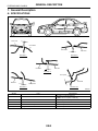
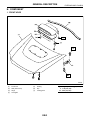
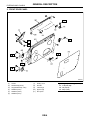
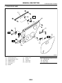
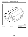
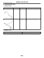
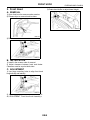
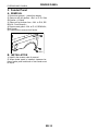
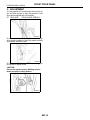
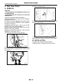
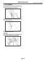
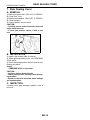
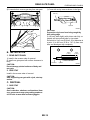
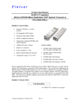
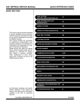
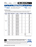
2001 IMPREZA SERVICE MANUAL
QUICK REFERENCE INDEX
BODY SECTION
This service manual has been prepared
to provide SUBARU service personnel
with the necessary information and data
for the correct maintenance and repair
of SUBARU vehicles.
This manual includes the procedures
for maintenance, disassembling, reassembling, inspection and adjustment of
components and diagnostics for guidance of experienced mechanics.
Please peruse and utilize this manual
fully to ensure complete repair work for
satisfying our customers by keeping
their vehicle in optimum condition.
When replacement of parts during
repair work is needed, be sure to use
SUBARU genuine parts.
All information, illustration and specifications contained in this manual are
based on the latest product information
available at the time of publication
approval.
FUJI HEAVY INDUSTRIES LTD.
HVAC SYSTEM
(HEATER, VENTILATOR AND A/C)
AC
HVAC SYSTEM (AUTO A/C)
(DIAGNOSTICS)
AC
AIRBAG SYSTEM
AB
AIRBAG SYSTEM (DIAGNOSTICS)
AB
SEAT BELT SYSTEM
SB
LIGHTING SYSTEM
LI
WIPER AND WASHER SYSTEMS
WW
ENTERTAINMENT
ET
COMMUNICATION SYSTEM
COM
GLASS/WINDOWS/MIRRORS
GW
BODY STRUCTURE
BS
INSTRUMENTATION/DRIVER INFO
IDI
SEATS
SE
SECURITY AND LOCKS
SL
IMMOBILIZER (DIAGNOSTICS)
IM
SUNROOF/T-TOP/CONVERTIBLE TOP
(SUNROOF)
SR
EXTERIOR/INTERIOR TRIM
EI
G1830GE6
2001 IMPREZA SERVICE MANUAL
QUICK REFERENCE INDEX
BODY SECTION
EXTERIOR BODY PANELS
EB
CRUISE CONTROL SYSTEM
CC
CRUISE CONTROL SYSTEM
(DIAGNOSTICS)
CC
G1830GE6
EXTERIOR BODY PANELS
EB
1.
2.
3.
4.
5.
6.
7.
8.
9.
Page
General Description ....................................................................................2
Front Hood ..................................................................................................9
Fender Panel.............................................................................................10
Front Door Panel.......................................................................................11
Front Sealing Cover ..................................................................................13
Rear Door Panel .......................................................................................14
Rear Sealing Cover...................................................................................16
Trunk Lid Panel .........................................................................................17
Rear Gate Panel .......................................................................................18
GENERAL DESCRIPTION
EXTERIOR BODY PANELS
1. General Description
A: SPECIFICATIONS
Front hood
Front fender
Front fender
Front door
SECTION B
SECTION A
Rear door
Front door
SECTION C
Door panel
Side sill
Rear door
Rear quarter
SECTION D
SECTION E,F
BO0260
Section
Part
A
Front hood to Front fender
B
C
D
E, F
Front fender to Front door
Front door to Rear door
Rear door to Rear quarter
Door panel to Side sill
Specification
NA: 4.0 ± 1.0 (0.16 ± 0.04 in)
TURBO: 3.7 ± 1.0 (0.15 ± 0.04 in)
4.7 ± 1.0 (0.19 ± 0.04 in)
5.1 (0.20 in)
4.6 (0.18 in)
5.9 (0.23 in)
EB-2
GENERAL DESCRIPTION
EXTERIOR BODY PANELS
B: COMPONENT
1. FRONT HOOD
BO0248
(1)
(2)
(3)
(4)
Front hood
Seal (Front hood)
Hinge
Hood grille
(5)
(6)
(7)
Packing
Clip
Locking piece
EB-3
Tightening torque: N·m (kg-m, ft-lb)
T: 7.35 (0.75, 5.4)
T1: 24.5 (2.5, 18.1)
GENERAL DESCRIPTION
EXTERIOR BODY PANELS
2. FRONT DOOR PANEL
BO0249
(1)
(2)
(3)
(4)
(5)
(6)
Gusset
Weatherstrip (Outer)
Clip (Weatherstrip, outer)
Stabilizer (Lifter)
Stabilizer (Outer)
Stabilizer (Inner)
(7)
(8)
(9)
(10)
(11)
Sealing cover
Checker
Lower hinge
Upper hinge
Door panel
EB-4
Tightening torque: N·m (kg-m, ft-lb)
T1: 7.35 (0.75, 5.4)
T2: 18 (1.8, 13)
T3: 30 (3.1, 2.2)
GENERAL DESCRIPTION
EXTERIOR BODY PANELS
3. REAR DOOR PANEL
BO0250
(1)
(2)
(3)
(4)
(5)
(6)
Weatherstrip (Outer)
Clip (Weatherstrip, outer)
Stabilizer (Outer)
Stabilizer (Inner)
Door panel
Bracket
(7)
(8)
(9)
(10)
Sealing cover
Checker
Lower hinge
Upper hinge
EB-5
Tightening torque: N·m (kg-m, ft-lb)
T1: 7.35 (0.75, 5.4)
T2: 18 (1.8, 13)
T3: 30 (3.1, 2.2)
GENERAL DESCRIPTION
EXTERIOR BODY PANELS
4. TRUNK LID PANEL
BO0251
(1)
(2)
(3)
Torsion bar
Trunk lid
Weatherstrip
(4)
(5)
Hinge ASSY
Cover
EB-6
Tightening torque: N·m (kg-m, ft-lb)
T1: 7.5 (0.76, 5.5)
T2: 14 (1.8, 13)
GENERAL DESCRIPTION
EXTERIOR BODY PANELS
5. REAR GATE PANEL
BO0252
(1)
(2)
(3)
Gas stay
Hinge
Rear gate
Tightening torque: N·m (kg-m, ft-lb)
T: 25 (2.5, 18.1)
C: CAUTION
• Exterior body panels are heavy. Do not drop and
damage the panels. During removal and installation, do not damage the panel painting surface.
• While removing mounting bolts, using assistance
devices such as a support jack will help support the
panel.
• Be careful not to lose small parts.
EB-7
GENERAL DESCRIPTION
EXTERIOR BODY PANELS
D: PREPARATION TOOL
1. SPECIAL TOOLS
ILLUSTRATION
TOOL NUMBER
925610000
DESCRIPTION
WRENCH
REMARKS
Used for removing and installing door hing.
REMOVER
Used for removing and installing trunk torsion
bar.
B5M1117
927780000
B5M1118
2. GENERAL TOOL
TOOL NAME
Support Jack
REMARKS
Used for supporting door panel.
EB-8
FRONT HOOD
EXTERIOR BODY PANELS
2. Front Hood
3) Rotate hood buffer to adjust lateral height.
A: REMOVAL
1) Open front hood to remove washer nozzles.
2) Release clips to remove hood insulator.
B5M0750
B5M1090
3) Remove bolts to disconnect hood from hinges.
B5M0747
B: INSTALLATION
1) Install in the reverse order of removal.
2) Adjust clearance between hood and fender.
Clearance must be equal at both sides.
C: ADJUSTMENT
1) Use hinge mounting holes to align front hood
longitudinally and laterally.
B5M0747
2) Adjust height at front end of hood. <Ref. to SL40, ADJUSTMENT, Front Hood Lock Assembly.>
EB-9
FENDER PANEL
EXTERIOR BODY PANELS
3. Fender Panel
A: REMOVAL
1) Disconnect ground (−) cable from battery.
2) Remove side sill spoilers. <Ref. to EI-19, Side
Sill Spoiler.> (If fitted)
3) Remove front bumper face. <Ref. to EI-8, REMOVAL, Front Bumper.>
4) Remove mud guard. <Ref. to EI-16, REMOVAL,
Mud Guard.>
5) Loosen bolts to remove front fender.
BO0153
B: INSTALLATION
1) Install in the reverse order of removal.
2) When fender panel is installed, clearance between fender panel and hood or front fender must
be equal.
EB-10
FRONT DOOR PANEL
EXTERIOR BODY PANELS
4. Front Door Panel
10) Remove door-side bolts for upper and lower
hinges to remove door.
A: REMOVAL
1) Disconnect ground cable from battery.
2) Remove front door trim. <Ref. to EI-20, REMOVAL, Front Door Trim.>
3) Remove outer mirror assembly. <Ref. to GW-46,
REMOVAL, Outer Mirror Assembly.>
4) Remove front door regulator and motor. <Ref. to
GW-31, REMOVAL, Front Regulator and Motor Assembly.>
5) Remove front door latch assembly. <Ref. to SL30, REMOVAL, Front Door Latch Assembly.>
6) Remove front outer handle. <Ref. to SL-29, REMOVAL, Front Outer Handle.>
7) Remove front pillar lower trim to disconnect connector from body harness.
G5M0385
11) Using special tool, remove body-side bolts for
upper and lower hinges, and remove door hinges.
ST 925610000
DOOR HINGE WRENCH
B5M0933A
B5M0726
8) Put wooden block on jack and place jack under
door. Support door with a support jack to protect it
from damage.
CAUTION:
• During removal and installation of doors, do
not damage body.
• Doors are heavy. Be careful not to drop and
damage them.
B: INSTALLATION
1) Install in the reverse order of removal.
2) Apply grease to sliding area of door hinges.
BO0261
9) Remove checker bolts.
S5M0183
EB-11
FRONT DOOR PANEL
EXTERIOR BODY PANELS
C: ADJUSTMENT
1) Using special tool, loosen body-side bolts of upper and lower hinges to align the position of front
door panel longitudinally and vertically.
ST 925610000
DOOR HINGE WRENCH
B5M0933A
2) Loosen door-side bolts of upper and lower hinges to align the position of front door panel vertically
and laterally at the front end.
G5M0385
3) Loosen screw (A) and tap striker (B) using plastic hammer to adjust striker.
CAUTION:
Do not use impact wrench. Welding area on
striker nut plate is easily broken.
B5M0934A
EB-12
FRONT SEALING COVER
EXTERIOR BODY PANELS
5. Front Sealing Cover
A: REMOVAL
1) Remove front door trim. <Ref. to EI-20, REMOVAL, Front Door Trim.>
2) Remove front speaker. <Ref. to ET-10, REMOVAL, Front Speaker.>
3) Using a spatula, remove sealer.
CAUTION:
• Carefully remove sealer. Excessive force will
easily break the cover.
• If cover gets broken, replace it with a new
one.
G5M0391
B: INSTALLATION
1) Install in the reverse order of removal.
2) When replacing sealing cover, use CEMEDINE
5430L sealer.
3) Press sealer-applied area firmly to prevent any
floating on surface.
Sealer:
CEMEDINE 5430L or equivalent
CAUTION:
• Apply a uniform bead of sealer.
• Attach sealing cover, keeping it from becoming wrinkled.
• Breaks in the bead will allow water leakage
and contamination.
C: INSPECTION
If sealing cover is damaged, replace it with a new
one.
EB-13
REAR DOOR PANEL
EXTERIOR BODY PANELS
6. Rear Door Panel
9) Remove checker bolts.
A: REMOVAL
CAUTION:
• During removal and installation of doors, do
not damage body.
• Doors are heavy. Be careful not to drop and
damage them.
1) Disconnect ground cable from battery.
2) Remove rear door trim. <Ref. to EI-21, REMOVAL, Rear Door Trim.>
3) Remove rear door regulator and motor assembly. <Ref. to GW-34, REMOVAL, Rear Regulator
and Motor Assembly.>
4) Remove rear door latch. <Ref. to SL-34, REMOVAL, Rear Door Latch Assembly.>
5) Remove rear outer handle. <Ref. to SL-33, REMOVAL, Rear Outer Handle.>
6) Remove center pillar lower trim. <Ref. to EI-29,
REMOVAL, Lower Inner Trim.>
7) Disconnect connector of door harness.
S5M0183
10) Remove door-side bolts for upper and lower
hinges to remove door.
G5M0385
11) Using special tool, remove body-side bolts for
upper and lower hinges, and remove door hinges.
B: INSTALLATION
1) Install in the reverse order of removal.
2) Apply grease to sliding area of door hinges.
BO0154
8) Put a wooden block on the jack and place the
jack under the door. Support the door with the jack
to protect it.
BO0261
EB-14
REAR DOOR PANEL
EXTERIOR BODY PANELS
C: ADJUSTMENT
1) Using special tool, loosen body-side bolts of upper and lower hinges to align the position of rear
door panel longitudinally and vertically.
B5M0933A
2) Loosen door-side bolts of upper and lower hinges to align the position of rear door panel vertically
and laterally at front-end.
G5M0385
3) Loosen screw (A) and tap striker (B) using plastic hammer to adjust striker.
CAUTION:
Do not use an impact wrench. The welding area
on the striker nut plate is easily broken.
B5M0934A
EB-15
REAR SEALING COVER
EXTERIOR BODY PANELS
7. Rear Sealing Cover
A: REMOVAL
1) Remove rear door trim. <Ref. to EI-21, REMOVAL, Rear Door Trim.>
2) Remove rear speaker. <Ref. to ET-12, REMOVAL, Rear Speaker.>
3) Using a spatula, remove sealer.
CAUTION:
• Carefully remove sealer. Excessive force will
easily break the cover.
• If cover gets broken, replace it with a new
one.
G5M0391
B: INSTALLATION
1) Install in the reverse order of removal.
2) When replacing sealing cover, use CEMEDINE
5430L sealer.
3) Press sealer-applied area firmly to prevent any
floating on surface.
Sealer:
CEMEDINE 5430L or equivalent
CAUTION:
• Apply an uniform bead of sealer.
• Attach sealing cover, keeping it from becoming wrinkled.
• Breaks in the bead will allow water leakage
and contamination.
C: INSPECTION
If sealing cover gets damaged, replace it with a
new one.
EB-16
TRUNK LID PANEL
EXTERIOR BODY PANELS
8. Trunk Lid Panel
B: INSTALLATION
A: REMOVAL
1. TRUNK LID
1. TRUNK LID
1) Install in the reverse order of removal.
2) Install trunk lid with uniform clearance.
1) Open trunk lid.
2) Disconnect trunk lid connector.
3) Loosen trunk lid mounting bolts to remove trunk
lid from hinges.
2. TORSION BAR
1) Install in the reverse order of removal.
2) Apply grease to rotating area of hinges and mating surface of torsion bar.
G5M0144
2. TORSION BAR
1) Open trunk lid.
2) Using special tool, remove torsion bar from
hinge link.
ST 927780000
REMOVER
CAUTION:
During removal and installation, carefully handle torsion bar. It will generate reactive force.
G5M0145
3) Remove right/left torsion bars.
CAUTION:
After the torsion bar is removed, the trunk lid
will slam shut. Be careful not to get hit by the
trunk lid.
EB-17
REAR GATE PANEL
EXTERIOR BODY PANELS
9. Rear Gate Panel
A: REMOVAL
1. REAR GATE PANEL
1) Open rear gate.
2) Remove rear gate outer handle. <Ref. to SL-36,
REMOVAL, Rear Gate Outer Handle.>
3) Remove rear gate latch assembly. <Ref. to SL37, REMOVAL, Rear Gate Latch Assembly.>
4) Remove rear gate key lock cylinders. <Ref. to
SL-43, REAR GATE, REPLACEMENT, Key Lock
Cylinders.>
5) Remove rear wiper. <Ref. to WW-21, REMOVAL, Rear Wiper Motor.>
6) Disconnect connectors of rear wiper, rear defogger, and other lighting devices.
7) Disconnect washer hose.
8) Remove rubber duct (A) connection, and pull out
harness and washer hose from rear gate.
CAUTION:
When the rear gate is released, it may hit and
damage the body. To prevent this, place a shop
cloth between body and gate.
10) Loosen rear gate bolts to remove rear gate.
BO0278
2. GAS STAY
1) Open rear gate. Using a support jack to support
the rear gate.
BO0262
B5M0733A
9) Using a support, support the rear gate while removing gas stay mounting bolts.
CAUTION:
• After gas stay is removed, rear gate cannot
stay open. Supporting the rear gate with a jack,
remove the bolts.
• Do not damage piston rods and oil seals.
• Never disassemble cylinders: They contain
gas.
BO0262
BO0155
EB-18
REAR GATE PANEL
EXTERIOR BODY PANELS
2) Loosen bolts to remove gas stay from rear gate.
1) Cover with a vinyl case as shown in the figure.
Gas stay
Vinyl sack
BO0264
CAUTION:
Prevent the vinyl case from being caught by
drill cutting edge
2) Lift body side slightly with piston rods fully extended, and secure body side on vise stand.
Drill a hole in 2 to 3 mm (0.08 to 0.12 in) diameter at
a point 10 to 200 mm (0.39 to 7.87 in) from door
side, and bleed gas stay completely.
Body side
Door side
BO0156
B: INSTALLATION
190mm
(7.48 in)
10mm
(0.39 in)
1. REAR GATE PANEL
1) Install in the reverse order of removal.
2) Install rear gate panel with uniform clearance to
body.
CAUTION:
Do not damage painted surfaces of body and
rear gate.
2. GAS STAY
Install in the reverse order of removal.
CAUTION:
After supporting rear gate with a jack, start operation.
C: DISPOSAL
1. GAS STAY
CAUTION:
Gas is colorless, odorless, and harmless. However, gas pressure may spray cutting powder or
oil. Be sure to wear dust-resistant goggles.
EB-19
Portion to be drilled
Piston rod
Cylinder
BO0263
REAR GATE PANEL
EXTERIOR BODY PANELS
EB-20