1
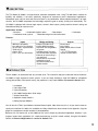
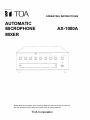
OPERATING INSTRUCTIONS
AUTOMATIC
MICROPHONE
MIXER
AX-1000A
Please follow the instructions in this manual to obtain the optimum results from this unit.
We also recommend you to keep this manual handy for future reference.
TOA Corporation
CONTENTS
Description
3
Introduction
3
Features
NOM Attenuation
900 Series Compatibility
Channel Direct Outputs
Logic Outputs
Input Channel Controls
NOM Attenuation Control
Other Features
4
4
4
4~5
6
6
1. Front View
7
2. Rear View
8
3. Installation
9
4. Input Signal Flow
Threshold Adjustment
Off-Attenuation
9
10
10
5. Input Connections
Choosing the Correct Modules
Specific Module Applications
11
15
10. Setup Procedure : Mic Input
Modules
16
11. Setup Procedure : Mic Channels
16
12. Fine-Tuning the AX-1000A
Installation
17
13. Using the AX-1000A System
Mute Bus
Configuration 1 : Internal Mute ; INT.
Priority Override
17
17
18
14. External Mute; EXT.: Using the 900
Series Module Mute Bus
Configuration 2 : Using Mute Receive
Modules
900 Series
15. Automatic Module Muting
Configuration 3 : Internal Mute
plus Automatic Module Muting
19
20
6. AX-1000A Configuration :
Quick Setup
Master Volume Control
NOM Attenuation Adjustment
11
16. Stacking (Multiple Mixing)
20~21
11
12
17. Application Ideas
21~22
7. Output Configuration
Main Output Connections
Remote Master Volume
Direct Outputs
Logic Outputs
12
12
13
13
8. Operation: Setup Checklist
General Operating Considerations
2
4
9. Setting Up Input Modules
Choosing Microphones
14~15
15
18. Block Diagram
23
19. Specifications
24
20. Appendix
Simplified Block Diagram
Setup Checklist
25
26~27
DESCRIPTION
The TOA Model AX-1000A is an eight-channel automatic microphone mixer. Using TOA 900 Series modules for
flexibility and reliability, it has been specifically designed for commercial sound reinforcement applications.
Microphone inputs may be mixed with line-level inputs in any combination. Where potential feedback is of major
concern, the AX-1000A incorporates the technology required to gate on quietly, quickly and automatically. The
AX-1000A is equipped with channel logic outputs, channel direct outputs, priority-override channel muting and
Master/Slave linking for up to ten units.
Applications include:
•Churches
• Combinable function rooms
• Conference center systems
• Boardrooms
• Courtrooms
• Teleconferencing and multi-media rooms.
Features:
Inputs
Mixing and Muting
Outputs
900 Series compatibility
Uses 900 Series input modules
Up to 8 inputs, any combination
of Mic and Line
Gate-on LEDs
Link In / Out: up to 80 channels
Adaptive Threshold circuit
Variable NOM AttenuationOutput Gain from 0 log NOM to
Direct Outputs
Logic Outputs
Master Remote Volume Control
terminal
transformerisolated, balanced output.
20 log NOM
Individual channel Threshold
and Off-Attenuation adjustment
Automatic or manual mixing is
user-configured
Internal Mute on any selected
combination of inputs
Input External Mute on any
mutable modules
INTRODUCTION
The AX-1000A is an economical and very versatile mixer. This manual will help you understand how to include the
AX-1000A in highly engineered sound systems. If you are simply installing a single AX-1000A for microphone
mixing (with perhaps a line input for music), the procedure is very simple. Basics are covered in Section 3~9:
3. Installation
4. Input Signal Flow
5. Input Connections
6. AX-1000A Configuration: Quick Setup
7. Output Connections
8. Operation: Setup Checklist
9. Setting Up Input Modules
You will also find TOA's Input Module Instruction Manual helpful. Most of the time, this is all you need to know to
specify and install the AX-1000A. An Installation and Setup Checklist has been included in the Appendix. Copy the
pages for a complete on-the-job reminder of setup operations.
Because of its rich feature set, an AX-1000A can be used in almost any commercial application. However, if you
progress beyond basic applications it is a requirement that you study this manual carefully. Using the AX-1000A's
controls in Advanced Applications is covered in Sections 7-11.
3
FEATURES
NOM Attenuation
The AX-1000A's NOM Attenuation circuitry automatically adjusts gain level according to the number of active
inputs. NOM = Number of Open Microphones. Most automatic mixers reduce output according to the formula 10
log NOM. When two mic inputs are active, the system gain is lowered 3 dB; when four are active, the output is
reduced by 6 dB; etc. TOA's NOM Attenuation circuitry allows adjustment from 0 to 20 log NOM depending on the
system specifications. Consequently, installations incorporating the AX-1000A deliver maximum acoustic gain
without feed back.
900 Series Compatibility
Each of the AX-1000A's eight input ports accepts 900 Series Mic Level, Auxiliary, Phono, 600 ohm and 10k ohm
Bridging, Signal Generator Modules and the T-02 Module for Music-on-Hold. This allows the contractor or
specifying engineer ultimate flexibility in system design.
Up to ten AX-1000A mixers may be linked together to create a system with a maximum of 80 active input
channels. When units are linked, one mixer in the chain is the Master. This is accomplished by setting the
rear-panel Master/Slave switches.
In addition to the Main Output, the AX-1000A provides Direct and Logic Outputs for each channel.
Channel Direct Outputs
Channel Direct Output uses are limited only by the application. For example, direct signals can be input to a
logging recorder to provide an account of courtroom proceedings while the mixer controls the communications
system itself. Or, the Direct Outputs from certain channels can be fed into a second mixer or mixer-amplifier.
Logic Outputs
The Logic Output is an isolated open collector circuit that will trigger external devices. Applications include video
camera control, tape recorder control, and control of distributed speaker systems.
Input Channel Controls
Each channel has an Input Volume Control.
This adjusts channel gain and allows balancing
the mixing among the eight audio sources.
Behind a front-panel security cover lie the trim
controls for each channel's Threshold and
Off-Attenuation. The Threshold control adjusts
the signal level at which the input switches from
'off' to 'on'. As automatic mixing occurs, the
AX-1000A uses this setting as the 'base line'
and changes each channel's Threshold in an
adaptive manner.
Off-Attenuation sets channel attenuation depth
when the gate is 'off'. Inactive inputs may be
attenuated from 0 dB to as much as 40 dB.
4
Variable Off-Attenuation
Adjustable Off-Attenuation allows the fine
adjustment necessary to assure smooth
channel turn on without missed syllables. When
Off-Attenuation is 0 dB, the mixer channel
functions as a normal mixer: there is no
attenuation of an inactive channel.
Variable Off-Attenuation
Note : When Off-Attenuation is set to 0 dB, the AX-1000A still utilizes the channel's active/inactive status
for its automatic mixing logic.
To change the automatic mixing function, use the NOM Attenuation control.
Example : Here's an unusual example that shows how flexible the AX-1000A can be. Imagine a game show
produced by a small organization with its own video studio where a single mixer must work in a wide
variety of situations.
Perhaps this game show is staged as part of employee training.
An AX-1000A can be configured as four channels of normal mixing (sound effects source, studio
paging mic with press-to-talk switch, BG/FG music cassette, and MC's lavalier mic) with four channels
of automatic mixing (four panelists or game contestants). The only requirement is to set the
Off-Attenuation appropriately.
In this example, the module complement would be :
Input
Module
MC*
Mic
Paging
Mic
Sound FX
Aux
BGM/FGM
Aux
Person 1
Person 2
Person 3
Person 4
Mic
Mic
Mic
Mic
Off-Attenuation
0 dB... channel always on
0 dB... channel always on
because mic is PTT.
0 dB... channel always on
0 dB... channel always on
40 dB... automatic
40 dB... automatic
40 dB... automatic
40 dB... automatic
* Threshold could be reset to moderately high level to
gate out rustling clothes.
5
NOM Attenuation Control
The NOM Attenuation Control is variable between 0 log NOM and 20 log NOM. This allows the AX-1000A to be
adjusted for virtually any multi-microphone application.
Often, each microphone in an acoustic space exhibits a particular feedback mode, different from the other
microphones. In these cases, 10 log NOM reduces the gain too much when more microphones become active;
thus operating the system with lower gain than optimum. In such situations, a setting between 0 and 10logNOM
delivers less attenuation with each doubling of active inputs, therefore eliminating unnecessary attenuation.
Feedback modes in very reverberant spaces can be additive to degree that greater attenuation than normal is
needed with more mics on. A setting between 10 log NOM and 20 log NOM provides more gain reduction than
normal as additional microphones become active, preventing feedback.
Note: NOM Attenuation affects overall system gain and is totally independent from the input attenuation
depth function.
Attenuation
20logNOM
in dB
Multiple
AX-1000A's
One
AX-1000A
Variable
Attenuation
10logNOM
(normal)
Variable
Attenuation
0dB Attn
Inputs
Active Inputs
Inputs
(NOM)
Other Features
The AX-1000A's Priority Override Mute is especially attractive in conference systems where the chairman must
override other delegates. Selection of which channels mute when the Mute Terminals are shorted is preset with a
DIP switch. Mute Terminal can be alternatively routed to the module mute bus.
A Master Remote Volume Control may be wired to the Remote Master Volume Terminals on the rear-panel to
enable control of the system's overall output from a podium, projection booth, or similar location. The
Off-Attenuation, Threshold and NOM Attenuation Controls are hidden by a security cover to prevent unauthorized
or unnecessary adjustments.
The AX-1000A includes the hardware necessary for mounting in standard 19" equipment cabinets.
6
1. Front View
1. Input Volume Control
Adjusts input gain, after any gain stage(s) in the chosen 900 Series module.
2. Gate On/Off Indicator
Illuminates when the channel gates on.
3. Master/Slave Indicator
Illuminates when unit is the Master in a combinable system. Master/Slave switch is on the rear-panel.
4. Threshold Control
Adjusts the channel gate-on sensitivity. Turning fully counter-clockwise lowers the threshold, resulting in
maximum sensitivity.
5. Off-Attenuation Adjustment
Adjusts the inactive-input attenuation depth.
6. NOM Attenuation Control
Adjusts the operation of the automatic mixing system's gain-sharing circuitry. (0 log NOM is fully counterclockwise position; 20 log NOM is fully clockwise position.)
7. Master Volume Control
Adjusts the overall sound system level.
8. Power On/Off Switch and Indicator
LED illuminates when unit is turned on.
7
2. Rear View
1. Remote Master Volume Control Terminals
Use a 10k ohm linear potentiometer (10k ohms = no gain reduction; 0 ohm = full gain reduction).
2. Direct Outputs
Individual outputs for each of the eight inputs. The signal originates at the output of the module plugged into the
port; it is not gated by the mixer.
3. Logic Outputs
To trigger external devices.
4. System Mute Terminals
5. Link In
When more than one AX-1000A is being utilized, slaves are daisy-chained using Link In/Out.
6. Link Out
7. Main Output Terminals
150/600 ohm barrier strip outputs.
8. Channel Mute DIP Switches
Chooses which channels mute in response to a short across the System Mute Terminals. As shipped the
default is 'on' (channels respond to a short across the mute terminals).
9. Mute Function Select Switch
Muting may be set for Internal Mute; INT., or for External Mute; EXT. For further details see "Using the
AX-1000A System Mute Bus".
10. Master/Slave Selector
If multiple units are incorporated in a combinable system, one AX-1000A must be the Master. The additional
units must be set up as Slaves.
11. Module Input Ports
For up to eight inputs. Each active input requires a 900 Series Module. See TOA's Input Module Instruction
Manual.
12. AC Fuse
Replace only with a fuse of the same rating. Caution: If the fuse blows, please contact TOA dealer.
8
3. Installation
Unpacking and Inspection
Upon receiving the AX-1000A, please inspect it for any shipping damage. If damage is found, notify the carrier
immediately.
Rack Mounting
The AX-1000A requires 3-unit size. Mounting
brackets are provided. Remove the four
screws securing the case at the left and right
front. Attach the rack mounting brackets. Be
certain to only use the screws that are
included on the AX-1000A unit.
Note: Allow adequate ventilation: do not block the vents in the cover. Do not locate the AX-1000A :
In unventilated areas.
Where it is exposed to direct sunlight.
In an area subject to heavy vibration.
In a dusty or extremely humid area.
In an area with a high ambient temperature,
or immediately adjacent to equipment which
generates large amounts of heat.
Caution : There are no user-serviceable parts inside. Never remove the cover, or you run the risk of a fatal
electric shock.
4. Input Signal Flow
Since the AX-1000A has eight input ports for 900 Series plug-in modules, it is completely flexible. Requirements
often vary from installation to installation, and the AX-1000A can be configured exactly to suit each one. In order to
change a given channel's function, simply specify the proper 900 Series input module. The signal flow from the
output of the module(s) is the same for every channel. See Figure 1.
This simplified 'map' of the signal flow does not represent the actual circuitry, only the stages of processing
that occur. Functions that occur after the signals reach the Mixing Bus have been omitted for clarity.
External/Internal Mute buses :
The AX-1000A has two Mute buses, External Mute Bus and the AX-1000A Internal Mute Bus. Each one
can operate independently, and each one operates at a different stage of the signal chain. Configuring
mutes is explained in detail, below.
9
Channel Signal Flow (simplified)
Input
Ch. 1
Logic Output
Direct Output
Mute
Terminals
Threshold Adjustment
The heart of an automatic mixer is the circuit that determines which inputs should gate on and which inputs should
remain off. The AX-1000A does this by comparing constantly and rapidly an individual channel's level and the
levels of all the inputs. This adaptive threshold system results in very smooth mixing.
Channel threshold determines how easily an input gates 'on'. Once the channel is 'on', the gating circuit
incorporates a preset Hold, 200 msec long, to keep the mic channel open between words as an individual speaks.
Channel threshold settings will vary from installation to installation since they depend on the acoustics of the site. If
Threshold is set too low (too sensitive), ambient noise may cause a channel's gate to flutter open and closed
randomly. If it is too high, the input will not gate open reliably when presented with a low-level signal. However,
these represent extremes. The AX-1000A's mixing circuitry works well over a range of 'middle ground' threshold
settings.
If the Threshold control is turned fully counter-clockwise, the channel remains on all the time.
Off-Attenuation
When a channel gates 'off', the output of the channel is attenuated. The factory setting is maximum attenuation, 40
dB. This is considered 'completely inaudible' for all practical purposes.
There may be applications in which an absence of ambient noise in the mix would be objectionable, or
where switching to full-attenuation would sound overly disruptive. Therefore, the Off-Attenuation may be set
at a lower level, such as 10 to 15 dB.
You may have other applications where less-than-full channel attenuation is desirable.
10
5. Input Connections
Choosing the Correct Modules
Select the combination of Mic and Line inputs to suit the application. All of the input ports are the same, so arrange
the inputs according to the logic the operator will use at the site. Most of the time, Standard Mic Modules and
Standard AUX Modules will be the proper, economical choice.
Reminder: Remove Jumper on any "M" module when used with dynamic or battery-powered condenser mics. This
defeats the module's built-in phantom power, reducing the possibility of noises from faulty cables or connectors.
Specific Module Applications
There may be specific situations which call for a special input module. There may be applications where
Compression or Remote Volume would be useful.
When a 600 ohm balanced line input is required, use a line matching input module.
When a 10k ohm bridging input is required, a bridging input module should be used.
If a signal must be split between the AX-1000A and an input elsewhere, employ an aux input/line output
module.
Make sure the AC power is off before inserting or
removing modules. Plug each module into its input port
by sliding it between the guide rails. Secure each
module with two screws. Cover unused ports with
blank panels.
6. AX-1000A Configuration : Quick Setup
The AX-1000A has been designed for quick, efficient configuration, installation, and operation. In most situations,
just fill the ports with Standard Mic Modules. When the specified mics are not phantom-powered, remove a Jumper
on the Standard Mic Module before inserting it into the port.
If a high-impedance mic is used in the system, use a High Z mic module.
If a line input is specified, use the Standard Aux Module.
Do not change the setting of the NOM Attenuation Control from its factory-set 10 log NOM position. Do not change
the Off-Attenuation Control on each channel from its factory preset.
Master Volume Control
The Master Volume Control allows sensitive adjustments to the overall system output. Ordinarily, after the Master
Volume Control is set, system gain is held constant by the automatic mixing circuitry. However, in complex
combinable systems with many inputs it may be necessary to boost or attenuate the overall gain as different
rooms are combined.
11
NOM Attenuation Adjustment
The typical automatic mixer reduces its output gain according to the formula 10 log NOM, where NOM refers to the
"Number of Open Microphones" --that is, the number of microphones which are active at any given instant. If two
channels are gated "on", the mixer's overall output gain is reduced 3 dB; if four are "on", the master gain is
reduced 6 dB; and so on.
In some cases it might be important to adjust attenuation differently. For example, if microphones are set up in
very close proximity to loudspeakers, or if the acoustic space is extraordinarily reverberant, the master gain should
be attenuated by a factor greater than 10 log NOM. This gives better feedback protection as more channels gate
"on". On the other hand, if the AX-1000A is located in an extremely dead acoustic space, attenuation at less than
10 log NOM will result in smoother automatic mixing.
The AX-1000A can be operated as a conventional manual mixer with the NOM Attenuation set to 0 log NOM.
7. Output Configuration
Main Output Connections
Connect the power amplifier(s) to the output terminals.
To choose 150 ohm output:
To choose 600 ohm output:
Remote Master Volume
If remote control of the master volume is required, utilize a 10k ohm linear potentiometer across these terminals.
The 10k ohm setting yields full volume, and the 0 ohm setting results in no output. Note that the Remote Master
attenuates from the level set by the Master Volume Control. It does not boost the volume.
Remote Master is useful for overall volume control when a security cover prevents access to Master Volume
Control.
If remote control of only one or two discrete volume setting is desired, use a toggle switch or a rotary switch with
fixed resistors to present the appropriate resistance across the Remote Volume Terminals.
For example, there may be a switch on the podium for "System Off" in one position, "Lecture/Discussion" in one
position, and "Movie/A-V" in a third position. This simplifies operation by untrained personnel.
Here, "System Off" would silence the AX-1000A by shorting the terminals; "Lecture/Discussion" would set the
volume to a middle value; and "Movie/A-V" would permit full volume.
12
Direct Outputs
The Direct Output from each channel appears
at a 1/4" mono phone jack. Each direct output is
an individually buffered tap of the signal
immediately after it has been processed by the
module. The state of the AX-1000A mixing
INPUT
CH.1
system has no effect on the direct signal. For
example, a Compressor Mic Module's direct
Direct Output
output will be compressed by the amount set on
the module itself; however, the direct signal is
not affected when the Internal Mute is invoked;
and it will not gate on and off as the AX-1000A's
automatic mixing circuitry operates.
Each direct output has a 680 ohm series resistor. Recommended load impedance is 5k ohms or greater. Direct
outputs can be tied together and passively mixed. Because each Direct Output is individually buffered, this type of
hard wire mixing does not cause additional crosstalk between channels. However, the level of each channel goes
down in a hard wired Direct Output mix as more channels are added to such a mix.
For example, if Direct Out 1 and 2 are placed in parallel, the signals will mix with a 6 dB drop in channel direct
level. An additional 6 dB drop occurs each time the number of parallel outputs is doubled.
Logic Outputs
Each channel's logic output is an isolated open-collector circuit. When a channel has gated open, the E and C
terminals present a short. Hook up according to standard open-collector procedures.
Note: Positive DC voltage should never be applied to the E terminal. AC voltage should never be hooked
up across these terminals.
The load on logic outputs should be equal to or
greater than 800 ohms. Maximum rating for logic
output is 30 mA at 24 V DC.
C
E
13
8. Operation: Setup Checklist
Insert the modules. Connect the output of the AX-1000A to the system power amplifier input. Connect the input
sources according to the following checklist. For more specific instructions, see Sections 9~12. Look in the
Appendix for a checklist which can be copied for use at the job site.
1. Insert each Mic input module.
(1) Choose Mic to use.
(2) Defeat phantom power if appropriate.
(3) Insert module.
(4) Connect input source.
(5) Repeat on each input.
2. Adjust Mic Module.
(1) Power-up mixer, raise Master Volume and one channel's Input Volume.
(2) Adjust module gain, low-cut filter and any other functions on module.
(3) Turn Input Volume off.
(4) Repeat on each input.
3. Set up Maximum Gain on Mic Channel(s).
(1) Set Channel Volumes and Master Volume 'off'.
(2) Confirm that NOM Attenuation is in the center detent.
(3) Confirm that all Off-Attenuation Adjustments are fully counter-clockwise (-40 dB).
(4) Adjust the Master Volume to the desired nominal operating level.
Maximum signal to noise is achieved with input volumes set between one o'clock and four o'clock. Set
Master Volume so that as many input volumes as possible can be set at optimum, keeping in mind desired
overall acoustic level.
(5)
(6)
(7)
(8)
Adjust input volume to a level just below feedback; log or mark setting.
If a channel gates on due to ambient noise, raise the Threshold (use Gate LEDs as a guide.).
Lower Input Volume to zero.
Repeat on each input.
4. Insert and Set Up Line Input Modules.
(1) Connect input, adjust module gain.
(2) Adjust Input Channel Volume.
(3) Repeat for each line input.
5. Insert and Set Up Special-Function modules.
(1) Connect input, adjust module gain, other function(s).
(2) Adjust Input Channel Volume.
(3) Repeat for each special-function module.
14
6. Final Adjustments
(1) Reset master volume to off.
(2) Reset all input channel volume to settings previously logged or marked.
(3) Set master volume for desired acoustic level. (Do not exceed setting arrived at in 3.(4) above.)
(4) Mixer is ready for use.
General Operating Considerations
The AX-1000A is only one component in a complex acoustic environment which includes the room itself, the
speakers throughout the space, the microphones and cables, the number of mics being used, the power
amplifier(s) and equalizers. In the long run, the sound system's performance depends more on day-to-day
consistency than on any other single factor.
For best results, plan a system so that the inputs to the AX-1000A are consistent. By the same token, make sure
that the system components coming after the AX-1000A are operated in a consistent fashion:
Use the same mics in the same inputs all the time.
Set portable mics in the same spots whenever possible.
Use the same Master Volume setting and system EQ curve all the time.
If the speakers are portable, set them up in the same spots all the time.
Use the same power amplifier setting all the time.
If there will be several people connecting up the mics at different events, make sure they have the base line
settings on hand to begin a session from the same setup every time.
9. Setting Up Input Modules
Choosing Microphones
Any microphone will work with the AX-1000A, but better-quality microphones yield higher gain before feedback.
Omnidirectional microphones are not recommended if feedback is a major concern. The exception: when lavalier
mics are required.
For best results, follow these guidelines:
Use only one model of cardioid (hypercardioid) mic throughout the system, such as TOA Dynamic Mics or
Condenser Mics.
If using only one model of mic is impossible, use the same model of mic in the same channel consistently.
In other words, if different brands of mics are constantly plugged into different inputs, the automatic mixing will not
work as well as it will when each mic is assigned to its own input.
After all, you set each channel's gain to the maximum before feedback with a certain microphone. Because
different mics differ in output level and frequency response, the module Gain and Input Channel Volume settings
will differ. If mics get swapped from input to input without channel volume readjustment, some mics could wind up
with too much gain and feedback can occur. Other channels will not have enough gain (at the module input itself),
and will fail to gate-on consistently.
In addition, matching specific mics to specific inputs means that phantom power can be disabled on channels
using dynamic or battery-powered condenser mics. This increases system reliability by preventing noises which
can occur due to faulty cables or connectors.
15
10. Setup Procedure : Mic Input Modules
Begin with Input 1. Make sure all Channel Volume controls are off. Set the Master Volume at approximately one
o'clock. Maximum signal to noise is achieved with input volumes set between one o'clock and four o'clock. Set
Master Volume so that as many input volumes as possible can be set at optimum, keeping in mind desired overall
acoustic level.
Raise the volume on the channel a moderate amount, and change the Master Volume as necessary until you can
hear the signal. If necessary, change the module's Gain.
Because each individual channel senses input level in order to operate automatically, use the Low Cut filters on
M-Series modules. Low Cut filtering eliminates stray low frequency energy. Quality microphones pick up this
energy, which has noting to do with intelligibility. The AX-1000A has circuitry which reduces triggering via low
frequencies, yet Low-Cut filters on modules can further reduce false gating.
Turn the Channel Volume on Input 1 off. Continue setting the input modules for all channels.
11. Setup Procedure : Mic Channels
Now you will set the channel volume controls to the maximum gain before feedback on all microphone inputs.
Begin with all channel volume controls off. First:
Make sure that the NOM Attenuation control is set to the detent (10logNOM).
Make sure that no muting functions are engaged.
Make sure that the Off-Attenuation control is set to maximum attenuation on each channel.
Make sure that the Threshold Control is at maximum sensitivity, (full counter-clockwise)
Have someone talk into the first microphone in the same manner in which it will be utilized. Slowly increase the
gain with the Channel Volume control until feedback is heard. Decrease the gain slightly until the ringing
disappears. Log or mark this setting and turn the channel volume off.
Repeat this procedure with every other microphone. You may log or mark the maximum positions; each channel's
gain should not be increased beyond this maximum point, and the Master Volume should not be increased either.
Always mix by decreasing these level to balance the volume of individual inputs.
After volume has been adjusted, raise each channel's threshold so it will gate on reliably, yet not be false-triggered
by typical ambient noise.
16
12. Fine-Tuning the AX-1000A Installation
In certain situations, more control over channel Off-Attenuation and system NOM Attenuation is desired.
First, set up the input modules. Then choose the specific inputs which need less than 40 dB of Off-Attenuation and
adjust the controls accordingly.
Finally, select NOM attenuation from 0 to 20 log NOM as required. Set Master Volume appropriate for one
channel. In typical operational circumstances, determine proper NOM setting when many mics are gated "on". If
feedback does not occur in such a situation, turn NOM control slightly toward 0 logNOM, retest, and readjust if
necessary. Similarly, if feedback does occur when many mics gate "on", turn NOM control slightly toward the 20
log NOM position and retest.
13. Using the AX-1000A System Mute Bus
Definitions:
AX-1000A System Mute Bus refers to the Mute Terminals and associated internal circuitry.
Internal Mute; INT.
Refers to an internal AX-1000A mute bus setup which allows certain channels to be shut off in response to a short
across the Mute Terminals.
External Mute; EXT.
Refers to the external muting (900 Series module mute) scheme.
Automatic Module Mute
Refers to a second, independent muting scheme which can be designed into an AX-1000A by choosing the proper
modules.
Internal "Internal Mute; INT" muting occurs at the output of each channel after the direct output and before the
signal reaches the mixing bus. When the terminals on the rear-panel are shorted, any channel which has been set
to mute via the Channel Mute Switches will do so. See the following Configuration 1.
However, the Direct Outputs will not be muted. If the Direct Outputs must be muted, select 900 Series 'mute
receive' modules. See Configuration 2 on page 19.
Configuration 1 : Internal Mute; INT.
A typical application is for a chairman's switch to silence all the delegates in a large meeting room.
Internal Mute occurs with in the mixer, after the signal has left the input module itself. Thus, any channel can be
muted. The module does not have to be a 900 Series 'muting module', its channel simply must be chosen on the
rear-panel DIP Channel Mute Switches. Furthermore, the Direct Output of the channel will not be affected by the
muting.
As shipped, the default is 'on' (channels respond to a short across the mute terminals). To configure Internal Mute;
INT., locate the Channel Mute DIP switch on the rear-panel of the unit. Set the switch corresponding to the
channel(s) which must mute.
17
Priority Override
– Does not affect the Direct Output.
Configuration 1:
Internal Mute;
INT.
Signal Output Chart
DIP switch controls which channels mute. All channels respond to Mute command.
When System Mute contact closure is received:
Output ?
DIP
SWITCH
MODULES:
1
Mic
2
Mic
3
4
Mic, mute to 'on' *
Mic, mute to 'off **
5
Aux with Mute
6
Aux with Variable Mute *"
7
Aux
Line Matching
8
POSITION:
TO MIX BUS
* Configured to turn 'on' in response to Module Bus mute command
** Configured normally, turns 'off in response to Module Bus mute command
*" Variable mute module with fade; set to attenuate 20db
18
DIRECT OUT
LOGIC OUT
14. External Mute; EXT. : Using the 900 Series Module Mute Bus
Configuration 2 : Using Mute Receive Modules
The Muting Mode Select on the rear-panel allows a choice of Internal Mute; INT. or External Mute; EXT. When set
for External Mute; EXT., only 900 Series Mute Receive modules respond to the contact closure. Other modules
continue to function normally.
This is because the AX-1000A rear-panel Mute Terminals have been connected to module bus 2, the 900 Series
mute bus. For example, a Mute Aux Module will drop the line input signal 60 dB below its normal level.
900 Series
Modules with an "11" in their number are Mute Receive modules. Note that in this case, the Direct Output mutes
also.
Normally, this confers no advantage over the Internal Mute; INT. However, the Mute or Mute Mic Module can be
configured to turn on in the presence of the mute command. There are some installations where certain mic
input(s) must be turned on, and others turned off, in response to a contact closure across the a Mute Terminals.
Configuration 2:
External Mute;
EXT.
Signal Output Chart
DIP Switch has no effect. Modules respond to Mute command if and only if they are "Mute Receive".
When System Mute contact closure is received:
Output ?
DIP
SWITCH
MODULES:
1
Mic
2
Mic
3
Mic, mute to 'on' *
Mic, mute to 'off **
4
5
6
7
8
POSITION:
TO MIX BUS
DIRECT OUT
LOGIC OUT
Aux with Mute
Aux with Variable Mute ***
Aux
Line Matching
* Configured to turn 'on' in response to Module Bus mute command
** Configured normally, turns 'off' in response to Module Bus mute command
*** Variable mute module with fade; set to attenuate 20dB.
19
15. Automatic Module Muting
Configuration 3 : Internal Mute plus Automatic Module Muting
By using 900 Series Mute Send and Mute Receive modules, two simultaneous yet independent muting schemes
are possible. Internal Mute is set to Internal Mute; INT. At least one Mute Send Module (Input) is installed, and at
least one of the following input modules are installed: Mute or Mute Mic Module; Mute AUX Module; Bridging
Module with mute; Line Matching Transformer Module with mute.
These are 'mute receive' modules. Their output is attenuated in response to Ground on the 900 Series mute bus.
(The Line Matching Transformer Module (Input) is a 'mute send' module which closes the mute bus to ground in
the presence of a line-level input signal.)
In this configuration, Module Muting is automated. If functions independently of the AX-1000A Internal Mute
system. Using the Mute Send Line Matching Transformer Module and Mute Receive "11" modules, when a signal
appears at the Line Matching Transformer's input, any "11" series module responds to the mute command sent on
module bus 2.
Thus, one collection of modules can be set to respond to a mute command originating with Line Matching
Transformer Module(s). A second collection can be set to respond to the Internal Mute, that is, a short on the
System Mute Terminals.
16. Stacking (Multiple Mixing)
AX-1000A's can be linked for up to 80 input channels (10 units). The linking cable is available separately. If you
are installing "N" number of mixers, order "N-1" linking cables (1 for 2 mixers, 2 for 3, etc.).
Decide on a Master mixer. This should normally be the one at the top or the bottom of the stack. Slide the
Master/Slave switches on all other mixers to the Slave position. The Master/Slave LED will illuminate on the
Master unit, but not on the slave units. (The position of the Master/Slave switch has no effect on an AX-1000A
operating by itself.)
Daisy-chain the Link Out on the last Slave in the series to the Link In on the next Slave. Continue linking Slaves
until all have been linked. Connect from the final Slave to the Link In on the Master. Do not connect anything to the
Master's Link Out.
Take the Main Output from the Master and route it to the power amplifiers.
Adjust each input channel on each mixer using its Volume, Threshold, and Off-Attenuation Controls.
Adjust the NOM Attenuation Control on each mixer.
To set the overall system output, use the Master Unit's Master Volume.
For Remote Volume Control of the entire system, connect a 10k ohm linear potentiometer across the
Remote Volume Terminals on the Master unit only. If remote control of only one or two discrete volume
settings is desired, use a toggle switch or a rotary switch with fixed resistors to present the appropriate
resistance across the Remote Volume Terminals. This simplifies operation by untrained personnel.
20
To enable the System Mute, Select which channels should mute using the DIP switches on each AX-1000A.
Then connect all mute terminals in parallel. Connect all "left-side" System Mute terminals together and all
"right-side" terminals together. Do not cross.
Example: Here four AX-1000A's are linked. The
mute terminals are connected in parallel,
and a Remote Master Volume control is
connected to the Master unit.
17. Application Ideas
Churches
Most church sound systems have a moderate number of microphones. It is often the case that only one
microphone, perhaps two, are in use at any given time. To complicate matters, many churches have several
services each Sabbath and various classes, meetings and functions during the week. Typically a different person
will set up the sound for each event.
The AX-1000A is valuable in these applications, since it allocates all the system gain to the one microphone in
operation until more than one mic is on; it shuts the others off even though their channel volume controls are set at
operating level; and it refuses to let the mic in operating go into feedback. If two or more microphones are in use
simultaneously, the system gain is shared among them for maximum acoustical output.
Deeper NOM Attenuation inhibits feedback in very reverberant churches.
The AX-1000A performs these gating and mixing functions accurately and unobtrusively.
Conference Rooms
Company meeting room systems, boardroom systems, courtroom systems and sound systems for legislative
bodies are all variations on one basic installation. Multiple microphones with some sort of System Mute are usually
in place. Up to ten AX-1000A's may be combined, with up to 80 inputs. The primary advantage of the AX-1000A in
a conference room system is freedom from feedback when large numbers of open mics must be controlled.
In highly engineered systems the channel logic outputs offer automatic control for many kinds or audio and video
equipment.
21
With thirty, forty or fifty microphones, the margin of SPL before feedback can vanish in a conventional system.
Each open mic steals gain from the total available to the sound system. However, the AX-1000A switches unused
mics 'off' and shares the maximum possible system gain among all the active mics. This effectively puts a flexible
and unobtrusive 'ceiling, on the system's maximum output regardless of the number of mics in use. If the system
has been properly adjusted, feedback should not occur.
Good Ideas
TOA has done everything possible to make the AX-1000A as foolproof as possible, but as with any complex
equipment, overall system set-up can affect the unit's performance in the field.
In any application, it's a good idea to fasten a log of the Input Volume and Master Volume settings near the mixer.
Sometimes when a number of operators have access to a system, it's more efficient to mark the front-panel with
the base line settings. Use small stick-on dots available at any art-supply store.
In the same way, channels can be marked for a specific model of mic, or marked with the mic location.
Finally, in difficult acoustic environments, it is important that the microphones must be placed consistently in the
same spots. So it may be a good idea to 'spike' the locations of movable microphones on the floor with bits of
colored tape, and post a chart showing which mic(s) correspond to which colors.
22
18. Block Diagram
23
19. Specifications
Frequency response :
Total Harmonic Distortion :
20 to 20,000 Hz ±1 dB
Signal to Noise Ratio :
Better than 90 dB, with ail Vol. Min.
Less than 0.1 %, at 1 kHz signal input
Better than 77 dB, with Band Pass 20-20,000 Hz, Input Vol. Min.,
Master Vol. Max.
Inputs :
8 x Input port for TOA 900 Series modules
1 x Link In (stacking)
Input Sensitivity
Input ports; 100 mV,
and Impedance :
Outputs :
Link In; 100mV,
1 x Main output;
8 x Direct output;
Audio Signal
, balanced, transformer isolated
; Nominal -20 dBV (100 mV); Maximum +6 dBV (6.3V)
1 x Link out; 100mV,
8 x Logic out; isolated open collector (30 mA, 24V DC max.)
Controls :
8 x Input Volume
1 x Master Volume
8 x Threshold Control
1 x NOM Attenuation Control
8 x Off Attenuation Control
1 x Master/Slave Switch
1 x Set of 8 Channel Mute DIP Switches
1 x INT/EXT Mute Function Select Switch
Number of Max. Stacking :
Max. Attenuation Level :
20 dB per AX-1000A
Attenuation System :
10 log NOM (Number of Mic) typical
10 units (80 channels)
(Continuous adjustable from 0 dB to 20 logNOM dB )
Line Voltage :
Fuse :
120V AC, 60 Hz
0.5 A, 250 V, fast blow
Internal fuses not user accessible; see service manual.
Dimensions (W x H x D) :
420 x 133 x 280 mm (6.5" x 5.2" x 11.0")
19" EIA standard rack mountable (3-unit size)
Weight :
7.0kg(15.5lb.)
* Specifications are subject to change without notice.
24
20. Appendix
Simplified Block Diagram
Automatic Mixing Circuits omitted for clarity
Simplified Block Diagram
Automatic Mixing Circuits
omitted for clarity
Input
Ch. 1
Ch. 1 Logic Output
Ch. 1 Direct Output
Link Out
Main
Output
Mute
Terminals
25
Setup Checklist
Installed by:
AX-1000A Installation:
Mixer No.:
Input:
1.Source
Module:
2.
3.
4.
5.
6.
7.
8.
Notes:
1. Configure each Mic Input Module
a.
b.
c.
d.
*
Choose Mic to use.
Defeat phantom power if appropriate.
Insert module.
Connect input source.
Repeat on each input.
2. Adjust Mic Module
a. Power-up Mixer, raise Master Volume and
one channel's Input Volume.
b. Raise Input Volume, adjust module gain,
low-cut filter and any other functions on
module.
c. Turn Input Volume off.
* Repeat on each input.
26
3. Set up Maximum Gain on Mic Channels
a. Set Channel Volumes and Master Volume
'off'.
b. Confirm that NOM Attenuation is in the
center detent.
c. Confirm that all Off-Attenuation adjustments
are fully counter-clockwise (-40 dB).
d. Adjust the Master Volume to the desired
nominal operating level.
e. Adjust input volume to a level just below
4. Insert and Set Up Line Input Modules
feedback; log or mark setting.
f. If a channel gates on due to ambient noise,
raise the Threshold.(use Gate LEDs as a
guide).
g. Lower Input Volume to zero.
* Repeat on each input.
a. Connect input, adjust module gain,
b. Adjust Input Channel Volume.
* Repeat for each line input.
5. Insert and Set Up Special-Function Modules
a. connect input, adjust module gain, other
function(s).
b. Adjust Input Channel Volume.
*
Repeat for each special-function module.
6. Final Adjustments
a. Reset master volume to off.
b. Reset all input channel volume to settings
previously logged or marked.
c. Set master volume for desired acoustic level
(Do not exceed setting arrived at in 3. d.
above).
* Mixer is ready for use.
27
TOA Corporation
Printed in Japan
133-12-157-10