1
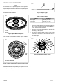
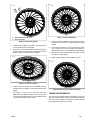
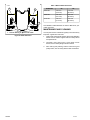
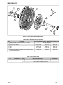
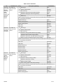
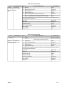
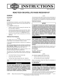
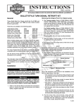
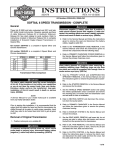
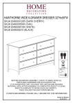
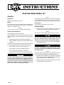
-J04243
REV. 2007-04-19
80-SPOKE REAR WHEEL KIT
GENERAL
NOTE
Kit Number
42962-08, 42959-08 and 40750-08
Models
This instruction sheet references Service Manual information.
A Service Manual for your model motorcycle is required for
this installation and is available from a Harley-Davidson Dealer.
Kit Contents
For model fitment information, please see the P&A Retail Catalog or the Parts and Accessories section of www.harleydavidson.com (English only).
NOTE
See the Service Parts section for kit contents.
INSTALLATION
1.
Accessory hub caps are not compatible with this wheel.
Additional Parts Required
This kit includes the custom wheel only.
Proper installation of this kit requires the separate purchase
of the following parts which are available at a Harley-Davidson
dealer:
•
Wheel Bearing Remover and Installer (HD-44060)
•
Wheel Installation Kit (See Service Parts Tables for part
number)
Remove existing rear wheel assembly. Save axle, axle
nut, brake disc and wheel spacers for kit installation.
NOTE
Remove the rear brake caliper before removing the wheel.
Do not re-use sprocket mounting screws. Re-using
sprocket mounting screws can result in torque loss and
damage to the sprocket and/or belt assembly. (00480b)
2.
Install the tube and tire on wheel. Refer to REAR WHEEL
in the Service manual.
The following Harley-Davidson Genuine Motor Accessories
are recommended for proper maintenance and cleaning:
•
Harley® Bright™ Chrome Cleaner (94683-99)
•
Harley® Glaze™ Polish and Sealant (99701-84)
•
Harley® Wheel and Spoke Brush (43078-99)
•
Harley-Davidson® Wheel and Tire Cleaner (94658-98)
The rider's safety depends upon the correct installation
of this kit. Use the appropriate service manual procedures.
If the procedure is not within your capabilities or you do
not have the correct tools, have a Harley-Davidson dealer
perform the installation. Improper installation of this kit
could result in death or serious injury. (00333a)
-J04243
Do not re-use brake disc screws. Re-using disc screws
can result in torque loss and damage to rotor and/or brake
assembly. (00319b)
NOTES
Install the primary bearing first using appropriate Service
Manual and WHEEL BEARING REMOVER/INSTALLER.
3.
Assemble wheel installation kit components and brake
disc(s) to wheel, using the appropriate service parts table.
Refer to REAR WHEEL in Service Manual.
4.
Install rear wheel (1), stock axle and stock axle nut. Refer
to REAR WHEEL in Service Manual.
1 of 7
WHEEL LACING PROCEDURE
is02693
A
NOTE
If only the rim is to be replaced, tape the spokes together to
hold the position on hub and remove spokes from rim. Install
taped hub/spoke assembly to the new rim and tighten spokes.
Then remove the tape and true wheels.
The nipple fitting of the spoke uses a standard T-30 TORX®
bit for removal and installation.
Figure 3. Spoke length
is02615
Table 1. Spoke Lengths
Spoke
1
2
1. Hub
2. Rim
Figure 1. Spoke Wheel Components
The 80-spoke wheel uses two lengths of spokes, installed in
the inner and outer rows on the hub. See Figure 2.
Length (A)
Outer spoke
5.19 inch (132 mm)
Inner spoke
5.59 inch (142 mm)
1.
See Figure 4. Place the hub on table with machined groove
side up. Insert a spoke in each hole of the outer row as
shown. Angle the spokes clockwise.
2.
Center the rim over the hub assembly with the valve stem
hole facing up. See Figure 5.
3.
See Figure 4. Using any outer row spoke, insert the first
spoke into the rim hole to the left of the valve stem hole
on the upper half of the rim centerline. Loosely assemble
the spoke nipple.
is02618
is02617
1
2
3
Figure 4. Install Outer Spokes on Hub
1. Inner spoke row
2. Outer spoke row
3. Machined directional groove
Figure 2. Spoke and Directional Groove Location on Hub
See Figure 3 and Table 1. Measure distance "A" (outer) to
determine outer and inner spoke lengths. Separate outer and
inner spokes in preparation for installation to hub and rim.
-J04243
2 of 7
is02619
2
is02621
1
Figure 7. Install Outer Spokes
1. Outer spoke location on rim
2. Valve stem hole
Figure 5. Install Outer Spokes
4.
5.
Install the rest of outer row spokes in every fourth hole.
Loosely assemble the spoke nipples.
See Figure 6. Insert the first inner row spoke into the hub.
Angle the spoke counterclockwise crossing four outer row
spokes. Loosely assemble the spoke nipples.
is02622
8.
Insert the remaining outer row spokes, angled counterclockwise, into hub and rim. Loosely assemble the spoke
nipples.
9.
Insert inner row spoke into hub and angle spoke clockwise, crossing over 4 outer row spokes. Place spoke into
appropriate rim hole. Loosely assemble the spoke nipples.
10. See Figure 8. Install remaining inner row spokes. Loosely
assemble the spoke nipples.
11. Tighten spoke nipples to 19-35 in-lbs (2.2-4 Nm).
is02623
Figure 6. Install Inner Spokes
6.
7.
Install the inner row spokes into every fourth remaining
hole above the rim centerline. Loosely assemble the spoke
nipples.
See Figure 7. Turn rim over so brake disc side faces
down. Place any outer row spoke into hub. Angle spoke
counterclockwise and insert into rim hole angled to accept
it. Loosely assemble the spoke nipple.
-J04243
Figure 8. Remaining Inner Spoke Installation
TRUING LACED WHEELS
The rim must be trued both laterally and radially. If new bearings were installed, wheels may be trued with only the bearings
and center spacer installed. See Figure 9 and Table 2 for the
proper offset dimensions for your wheel.
3 of 7
IS02624
Table 2. Wheel Offset Dimensions
A
Kit Number
B
"A"
"B"
42959-08
1.29 inch
(33.6 mm)
1.13 inch
(28.6 mm)
42962-08
1.41 inch
(35.7 mm)
1.05 inch
(26.6 mm)
40750-08
1.86 inch
(47.3 mm)
1.05 inch
(26.6 mm)
1
See TRUING LACED WHEELS the Service Manual for your
model motorcycle.
MAINTENANCE AND CLEANING
1. Cast-in marking or groove side of hub.
Figure 9. Offset Dimension
-J04243
Chrome parts must be maintained regularly to ensure that they
keep their original shine and luster.
1.
Clean heavily-soiled wheel surfaces using Harley-Davidson
Wheel and Tire Cleaner applied with the Harley Wheel
and Spoke Brush.
2.
Thoroughly clean chrome with a good quality chrome
cleaner, such as Harley Bright Chrome Cleaner.
3.
After cleaning and polishing, seal the finish with a good
quality sealer, such as Harley Glaze Polish and Sealant.
4 of 7
SERVICE PARTS
is04588
D
1
F
5
C
A
B
G
A
H
Figure 10. Service Parts: 80-Spoke Rear Wheel
Table 3. Wheel Assembly Service Parts Table
Item
Description
Part No. 42959-08 Part No. 42962-08 Part No. 40750-08
1
Wheel assembly (consists of items 2, 3, 4 and 5)
Not Sold Separately
2
Rim strip (not shown)
3
Rim
4
Hub
5
Spoke and nipple kit (contains 20 inner spokes, 20 outer
spokes and 40 nipples)
41899-05
43147-40
43147-40
43147-40
43087-04
43087-04
43087-04
41137-04A
41137-04A
40752-08
41899-05
41899-05
Table 4. Service Parts Table
Kit
42959-08
Installation Kit
Item
1
Description (Quantity)
Wheel
Part Number
Not sold separately
Items requiring separate purchase:
-J04243
5 of 7
Table 4. Service Parts Table
Kit
Installation Kit
2000-2005 Kit 43854-08
Dyna, 2000- 16x3 inch Rear
2004 XL,
Wheel
2000-2002
Softail
(except
FXSTD) and
2000-2001
Touring
Models
2002-2007
Touring and
2005-2007
XL Models
Kit 43861-08
16x3 inch Rear
Wheel
Item
Description (Quantity)
Part Number
A
Bearing (2)
9267
B
Sleeve, bearing spacer
43608-00
C
Disc screw (5)
43567-92
D
Sprocket screw (5) (Dyna and Softail models)
3737A
Sprocket screw (5) (XL and Touring models)
3899
Washer (5)
6516HW
F
NOTE: Discard the following components which are provided with this installation kit, but
are not required for this fitment.
Sprocket screw (5)
3109
Sleeve, bearing spacer
43618-06
Sleeve, bearing spacer
43618-07
Valve stem
43206-01
Valve stem
43157-83A
A
Bearing (2)
9247
B
Sleeve, bearing spacer
43517-00
C
Disc screw (5)
43567-92
D
Sprocket screw (5) (2004-2006 Touring models)
3737A
Sprocket screw (5) (2007 Touring models)
3109
Sprocket screw (5) (XL and 2002-2003 Touring models)
3899
Washer (5) (XL and 2006 and earlier Touring models)
6516HW
F
NOTE: Discard the following components which are provided with this installation kit, but
are not required for this fitment.
2008 and
Kit 43878-08
later Touring 16x3 inch Rear
(without
Wheel
ABS) and
2008 and
later XL
Models
Valve stem
43157-83A
Valve stem
43206-01
Sprocket washer (5)
7039
Sprocket bolt (5)
4552
Sprocket bolt (5)
40439-01
Sprocket screw (5)
3873
Sleeve, bearing spacer
43704-01
A
Bearing (2)
9276
B
Sleeve, bearing spacer
41900-08
C
Disc screw (5)
43567-92
D
Sprocket screw (5) (Touring models)
3814
Sprocket screw (5) (XL models)
3899
F
Washer (5) (XL models)
6516HW
G
Shim, bearing (install under primary bearing)
43904-08
NOTE: Discard the following components which are provided with this installation kit, but
are not required for this fitment.
-J04243
Valve stem
43157-83A
Valve stem
43206-01
Sprocket screw (5)
3109
Sleeve, bearing spacer
41696-08
6 of 7
Table 4. Service Parts Table
Kit
Installation Kit
2008 and
Kit 41453-08
later Touring 16x3 inch Rear
Models with Wheel
ABS
Item
Description (Quantity)
Part Number
A
Bearing
9276
B
Sleeve, bearing spacer
41900-08
C
Disc screw (5)
43567-92
D
Sprocket screw (5)
3814
G
Shim, bearing (install under primary bearing)
43904-08
H
Bearing, ABS (Red side of bearing must face inward)
9252
NOTE: Discard the following components which are provided with this installation kit, but
are not required for this fitment.
Valve stem
43157-83A
Valve stem
43206-01
Sprocket screw (5)
7039
Sleeve, bearing spacer
43704-08
Shim, bearing
41447-08
Screw,
TORX®
4552
Table 5. Service Parts Table
Kit
Installation Kit
40750-08
Item
1
Description (Quantity)
Wheel
Part Number
Not sold separately
Items requiring separate purchase:
2008 and
Kit 43878-08
later FLSTN 16x3 inch Rear
and FLSTC Wheel
A
Bearing (2)
9267
B
Sleeve, bearing spacer
41696-08
C
Disc screw (5)
43567-92
D
Sprocket screw (5)
3109
NOTE: Discard the following components which are provided with this installation kit, but
are not required for this fitment.
-J04243
Valve stem
43157-83A
Valve stem
43206-01
Sprocket screw (5)
3899
Sprocket screw (5)
3814
Sleeve, bearing spacer
41900-08
Shim, bearing
43904-08
Washer (5)
6516HW
7 of 7