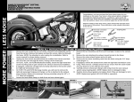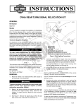
1
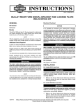
INSTRUCTIONS
REV. 4-23-04
-J02371
®
Kit Numbers 69063-03, 69147-03, 69153-03, 69337-03, 69338-03, and 69339-03
BULLET-STYLE TURN SIGNAL RETROFIT KIT
General
Removing the Original Front Turn Signal Lamps
2. For Touring models: Refer to TURN SIGNAL LAMPS:
FRONT TURN SIGNAL LAMP: REMOVAL in the appropriate Service Manual to access the AMP MULTILOCK
front turn signal connector [31] and disassemble the
turn signals from the vehicle.
These Bullet-Style Turn Signal retrofit kits fit all 1994 and
later Touring models, and 1996 and later Softail models
FLSTC/I and FLSTN.
These kits are available in the following styles:
Amber Lens, Clear Bulb
Clear Lens, Amber Bulb
Smoked Lens, Amber Bulb
HDI
HDI
HDI
PART NO.
69063-03
69147-03
69153-03
Rosto
ck
The other Bullet-Style Turn Signal retrofit kits are not
compatible with the Auxiliary Brake Light/ Turn Signal Kit.
See the Service Parts illustration on the last page of these
instructions for kit contents.
NOTE
This instruction sheet references Service Manual information.
A Service Manual for your model motorcycle is required for
this installation and is available from your Harley-Davidson
Dealer.
w
w
1WARNING
For Softail models: Refer to TURN SIGNALS/ RUNNING LIGHTS: LAMP REPLACEMENT in the appropriate Service Manual to access the AMP MULTILOCK
front turn signal connector [31] and disassemble the
turn signals from the vehicle.
erman
G
.
e
.
y
n
69337-03
69338-03
69339-03
When installing Amber Lens Turn Signal Retrofit Kit 6906303 on a vehicle that also has an Auxiliary Brake Light/ Turn
Signal Kit (Part Number 91699-99A) installed, Red Bullet
Turn Signal Trim Ring Kit (Part Number 69736-02) must be
installed in place of the Amber rear lenses. This kit is
available separately from your Harley-Davidson dealer.
Installation
.
w.
For all models: Save all lamp mounting hardware.
3. Note the location of all tie straps, so the new wiring can
be attached in the same locations.
4. Pull apart the pin and socket halves of the front turn signal connector [31].
NOTE
Record the color of each wire, its origin (left or right lamp) and
which cavity it was in before removing the terminals from the
socket (lamp-side) half of the connector.
o p. d e
FOR:
Domestic
Domestic
Domestic
5. See Figure 1. Remove the wires and terminals from the
socket housing [31B]. Attach a length of strong, flexible
mechanic’s wire to each terminal.
i05196
sh
LENS/ BULB TYPE:
Amber Lens, Clear Bulb
Clear Lens, Amber Bulb
Smoked Lens, Amber Bulb
Mechanic’s wire
h d o nli
To prevent accidental vehicle start-up, which could
cause death or serious injury, disconnect battery cables
(negative cable first) before proceeding. (00048A)
1WARNING
Disconnect negative (-) battery cable first. If positive (+)
cable should contact ground with negative (-) cable connected, the resulting sparks can cause a battery explosion,
which could result in death or serious injury. (00049A)
1. Refer to the Service Manual and follow the instructions
given to remove the seat and disconnect the battery
cables, negative cable first.
n
e
Socket terminal
Lamp wire
Figure 1. Mechanic’s Wire
NOTE
Use of the mechanic’s wires will aid in the installation of the
new turn signal lamps. Some tips:
• The mechanic’s wire should be strong enough to pull
the terminals and lamp wires through the conduit without breaking.
• The wires should be long enough to ensure that the
free ends are not lost in the conduit.
• See Figure 1. Feed each mechanic’s wire through the
opening in a socket terminal, then loop back, twisting
the end until tightly wound around the longer strand.
• Pull the lamp wires from one lamp at a time through
the conduit.
• Once the lamp wires and attached terminals are free
of the conduit, unfasten the mechanic’s wires from the
terminals before discarding the lamps.
6. Pull the lamp wires and terminals, along with the
mechanic’s wires, through the conduit to free the original lamps from the motorcycle. Leave the mechanic’s
wires in the conduit. Discard the lamps.
1 of 3
Installing the New Front Turn Signal Lamps
Installing the New Rear Turn Signal Lamps
1. Attach a mechanic’s wire to each terminal on the new
bullet-style front turn signal lamps.
2. Pull the mechanic’s wires, along with the terminals and
lamp wires from one lamp at a time back through the
conduit. Mark the wires to identify their origin (left or right
lamp) after they’ve been pulled all the way through the
conduit.
NOTE
If it becomes too difficult to insert the new lamp wires through
the conduit, the wires can be routed alongside the conduit,
then bound securely with tie straps from the kit.
3. Obtain the new socket housing from the kit. Insert each
terminal from the new lamps into the numbered cavity of
the new connector to match the original lamp connections.
2. Re-attach the wiring to the motorcycle with tie straps
from the kit, if originally installed.
1WARNING
Connect positive (+) battery cable first. If positive (+) cable
should contact ground with negative (-) cable connected,
the resulting sparks can cause a battery explosion, which
could result in death or serious injury. (00068)
For Softail models: Refer to TURN SIGNALS/ RUNNING LIGHTS: LAMP REPLACEMENT in the appropriate Service Manual to assemble the new front turn signals to the vehicle.
Removing the Original Rear Turn Signal Lamps
1. For Touring models: Refer to TURN SIGNAL LAMPS:
REAR TURN SIGNAL LAMP: REMOVAL in the appropriate Service Manual to disconnect the left [18] and
right [19] rear turn signal connectors, and disassemble
the turn signals from the vehicle.
w
w
For Softail models: Refer to TURN SIGNALS/ RUNNING LIGHTS: LAMP REPLACEMENT in the appropriate Service Manual to disconnect the left [18] and right
[19] rear turn signal connectors, and disassemble the
turn signals from the vehicle.
w.
4. Refer to the Service Manual, and follow instructions to
install the seat.
1WARNING
After installing seat, pull upward on front of seat to be
sure it is in locked position. While riding, a loose seat
can shift causing loss of control, which could result in
death or serious injury. (00070)
o p. d e
6. For Touring models: Refer to TURN SIGNAL LAMPS:
FRONT TURN SIGNAL LAMP: INSTALLATION in the
appropriate Service Manual to assemble the new front
turn signals to the vehicle.
3. Connect the battery cables, positive cable first.
1WARNING
Be sure that all lights and switches operate properly
before operating motorcycle. Low visibility of rider can
result in death or serious injury. (00316a)
5. Start the motorcycle and make sure that all four turn signals
function properly.
h d o nli
sh
5. Re-attach the wiring to the motorcycle with tie straps
from the kit.
Rosto
ck
For Softail models: Refer to TURN SIGNALS/ RUNNING LIGHTS: LAMP REPLACEMENT in the appropriate
Service Manual to assemble the new turn signals to the
vehicle, and re-connect the rear turn signal connectors.
erman
G
.
e
.
y
n
4. Connect the new socket housing to the front turn signal
connector pin housing [31A].
.
1. For Touring models: Refer to TURN SIGNAL LAMPS:
REAR TURN SIGNAL LAMP: INSTALLATION in the
appropriate Service Manual to assemble the new turn
signals to the vehicle, and re-connect the rear turn signal
connectors.
n
e
For all models: Save all lamp mounting hardware.
2. Note the location of any tie straps, so the new wiring
can be attached in the same locations.
-J02371
2 of 3
®
Service Parts
Part No. 69063-03 & others
Date 4/04
Bullet-Style Turn Signal Kit
i05197
5
6
4
NOTE For Kit 69063-03:
When Auxiliary Brake
Light/ Turn Signal Kit
(Part Number 91699-99A)
is also installed, the
Amber rear turn signal
lenses MUST be replaced
with Red Bullet Turn
Signal Trim Ring Kit
(Part Number 69736-02).
9
10
Rosto
ck
11
erman
G
.
e
.
y
n
8
3
o p. d e
Turn Signal Kit 69063-03 (Amber Lens, Domestic)
Item
Description
Part No.
1
Turn signal assembly, front (2)
69165-03
2
Lens assembly, Amber
69002-03
3
Bulb (Clear), S-8,
dual contact, bayonet base
68168-89
4
Turn signal assembly, rear (2)
69168-03
5
Lens assembly, Amber
69002-03
6
Bulb (Clear), S-8,
single contact, bayonet base
68572-64B
2
1
Turn Signal Kit 69338-03 (Clear Lens, HDI)
Item
Description
1
Turn signal assembly, front (2)
2
Lens assembly, Clear
3
Bulb (Amber), S-8, (E-approved)
single contact, bayonet base
4
Turn signal assembly, rear (2)
5
Lens assembly, Clear
6
Bulb (Amber), S-8, (E-approved)
single contact, bayonet base
Turn Signal Kit 69153-03 (Smoked Lens, Domestic)
Item
Description
Part No.
1
Turn signal assembly, front (2)
69203-03
2
Lens assembly, Smoked
69021-03
3
Bulb (Amber), S-8,
dual contact, bayonet base
69331-02
4
Turn signal assembly, rear (2)
69204-03
5
Lens assembly, Smoked
69021-03
6
Bulb (Amber), S-8,
single contact, bayonet base
69330-02
Turn Signal Kit 69339-03 (Smoked Lens, HDI)
Item
Description
Part No.
1
Turn signal assembly, front (2)
69344-03
2
Lens assembly, Smoked
69021-03
3
Bulb (Amber), S-8, (E-approved)
single contact, bayonet base
69348-03
4
Turn signal assembly, rear (2)
69345-03
5
Lens assembly, Smoked
69021-03
6
Bulb (Amber), S-8, (E-approved)
single contact, bayonet base
69348-03
Turn Signal Kit 69337-03 (Amber Lens, HDI)
Item
Description
Part No.
1
Turn signal assembly, front (2)
69340-03
2
Lens assembly, Amber
69002-03
3
Bulb (clear), S-8, (E-approved)
single contact, bayonet base
68163-84
4
Turn signal assembly, rear (2)
69341-03
5
Lens assembly, Amber
69002-03
3
Bulb (clear), S-8, (E-approved)
single contact, bayonet base
68163-84
Common Parts for All Kits
w
w
-J02371
w.
sh
Turn Signal Kit 69147-03 (Clear Lens, Domestic)
Item
Description
Part No.
1
Turn signal assembly, front (2)
69201-03
2
Lens assembly, Clear
69004-03
3
Bulb (Amber), S-8,
dual contact, bayonet base
69331-02
4
Turn signal assembly, rear (2)
69202-03
5
Lens assembly, Clear
69004-03
6
Bulb (Amber), S-8,
single contact, bayonet base
69330-02
h d o nli
Item
7
8
9
10
11
n
e
Description
Turn signal wiring kit
Housing, socket (6-way)
Strap, cable (8)
Tube, heat shrink (10)
Connector (10)
Part No.
69342-03
69004-03
69348-03
69343-03
69004-03
69348-03
Part No.
69207-03
73156-96BK
10065
67113-83
70581-73
3 of 3