1
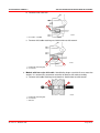
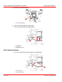
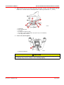
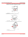
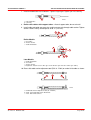
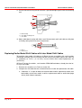
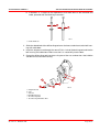
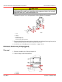
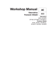
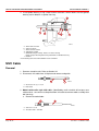
SERVICE MANUAL NUMBER 11
SERVICE PROCEDURES REQUIRING MINOR DISASSEMBLY
4. Install gimbal bearing, using a lead hammer and tools shown. Make sure that gimbal
bearing carrier bottoms in gimbal housing.
e
a
c
b
d
f
22118
abcde-
*Drive Rod 91-37323
*Plate 91-29310
*Drive Head 91-32325
*Mandrel 91-30366
Gimbal Bearing Assembly - Notches in Carrier Facing
Engine Coupler Bearing Carrier Beyond Chamfer in Gimbal Housing
f - Chamfer
* From Bearing Removal and Installation Tool 91-31229A7.
Shift Cable
Removal
1. Remove sterndrive unit. Refer to Section 2A.
2. Disconnect shift cable from shift plate and remove end guide.
b
a
22183
a - Anchor Screws (2) - Loosen
b - End Guide
3. Models with earlier style shift cable - (identified by small nut which will not pass over
cable anchor - core wire must be pulled from shift cable to remove cable assembly from
bell housing).
a. Remove threaded tube.
a
b
22183
a - Jam Nut - Loosen
b - Threaded Tube - Turn Out
Page 4A-20
90-17431--4 MARCH 1998
SERVICE MANUAL NUMBER 11
SERVICE PROCEDURES REQUIRING MINOR DISASSEMBLY
b. Remove inner core wire.
a
50327
a - Core Wire - Pull Out
c. Remove shift cable retaining nut. Hold inside nut with wrench.
a
22121
b
a - Shift Cable Retaining Nut
b - Inside Nut
4. Models with later style shift cable - identified by larger nut which fits over core wire
anchor; it is unnecessary to remove core wire to remove shift cable assembly.
a. Remove shift cable retaining nut and washer. Hold inside nut with wrench.
c
a
b
50323
a - Shift Cable Retaining Nut
b - Inside Nut
c - Washer
90-17431--4 MARCH 1998
Page 4A-21
SERVICE MANUAL NUMBER 11
SERVICE PROCEDURES REQUIRING MINOR DISASSEMBLY
5. Remove shift cable wrapping.
a
22030
a - Shift Cable Wrapping
6. Loosen shift cable bellows crimp clamp.
7. Pull shift cable through shift cable bellows.
a
b
c
50458
a - Crimp Clamp
b - Shift Cable
c - Shift Cable Bellows
Shift Cable Installation
1. Insert shift cable end into and through shift cable bellows.
a
b
50458
a - Shift Cable End
b - Shift Cable Bellows
Page 4A-22
90-17431--4 MARCH 1998
SERVICE MANUAL NUMBER 11
SERVICE PROCEDURES REQUIRING MINOR DISASSEMBLY
2. Apply Perfect Seal to shift cable retaining nut threads. Secure shift cable to bell housing.
Hold inner nut with wrench and torque outer retaining nut to 65 lb. in. (7 N·m).
f
d
a
e
abcdef-
50327
c
b
Shift Cable
Outer Retaining Nut
Inner Nut
Seal Washer (Hidden by Nut)
Core Wire is in Later Model Cable, only (at this step of reinstallation)
Later Style Cable - Washer
3. Install shift cable wrapping.
a
22030
a - Shift Cable Wrapping
CAUTION
Check that bellows end is not flattened out when crimping in the followIng step. Water leakage may result if clamp is not installed properly.
90-17431--4 MARCH 1998
Page 4A-23
SERVICE MANUAL NUMBER 11
SERVICE PROCEDURES REQUIRING MINOR DISASSEMBLY
4. Install and compress shift cable bellows crimp clamp, maintaining a 1/2 in. diameter
round O.D. Be sure that clamp is crimped evenly so that a good seal is maintained between bellows and shift cable. (Do not allow bellows to flatten.)
a
22117
a - Crimp Clamp
5. Models with earlier shift cable - install inner core wire.
a
50327
a - Inner Core Wire
6. Install core wire locating tool (P/N 91-17263) on face of bell housing.
a
b
50327
a - Bell Housing
b - Core Wire Locating Tool (P/N 91-17262A1)
Page 4A-24
90-17431--4 MARCH 1998
SERVICE MANUAL NUMBER 11
SERVICE PROCEDURES REQUIRING MINOR DISASSEMBLY
7. Install threaded tube until it bottoms. Tighten finger tight. Tighten jam nut securely.
a
b
22183
a - Threaded Tube
b - Jam Nut
8. Earlier shift cables with support tubes - discard support tube; do not reinstall.
9. Install cable end guide over core wire, and insert core wire through cable anchor. Tighten
anchor screws evenly and torque to 20 lb. in. (2.3 N·m).
c
b
a
b
Earlier Models
a - Core Wire
b - Anchor Screws
c - Cable End Guide
a
d
c
b d
c
Later Models
abcd-
Cable End Guide
Core Wire
Anchor Screws
Sight Port - bottom-out core wire (present on all later style and some earlier style cables)
10. Place shift cable anchor adjustment tool (P/N 91-17262) on end of shift cable as shown.
c
a
b
22120
a - Shift Cable Anchor Adjustment Tool (91-17262A1)
b - Stud - Placed through Hole in End Guide
c - Hole - Barrel Placed Here
90-17431--4 MARCH 1998
Page 4A-25
SERVICE MANUAL NUMBER 11
SERVICE PROCEDURES REQUIRING MINOR DISASSEMBLY
11. Ensure that bell housing end of core wire is positioned tight against core wire locating
tool.
a
c
b
22121
a - Bell Housing
b - Core Wire Locating Tool
c - Core Wire
12. Adjust cable barrel to align with hole in tool. Remove tools and install cable on shift plate
assembly, being careful not to lose adjustment.
a
b
22120
a - Barrel
b - Hole in Tool
Replacing Earlier Model Shift Cables with Later Model Shift Cables
To install the later model shift cable on all Brave transom assemblies with serial number
OD542204 and lower you must enlarge the bell housing shift cable retainer hole from 3/8
in. (9.525mm) to 7/16 in. (11.113 mm). Use the Bravo Shift Cable Replacement Kit
(815471A3).
All Bravo Transom Assemblies, serial number OD542205 and above, already have the latest style shift cable.
1. Remove the sterndrive unit. Refer to section 2A.
2. Compare the shift cable that was removed from the unit with the replacement shift cable.
a. If diameter “a” is equal on both the removed cable and the replacement cable, then
both cables are the later model. Install the replacement cable as outlined on page
4A-22 (Shift Cable Installation).
Page 4A-26
90-17431--4 MARCH 1998
SERVICE MANUAL NUMBER 11
SERVICE PROCEDURES REQUIRING MINOR DISASSEMBLY
b. If diameter “a” is larger on the replacement shift cable than on the removed shift
cable, proceed with the following instructions.
a
a
70377
a - Cable Diameter
3. Slide the slotted hole of the drill bushing tool over the lowest stud closest to the bell housing shift cable bore.
4. Install the alignment rod through the round 7/16 in. hole of the bushing tool and into the
bell housing shift cable bore. Make sure that it is seated fully into the bore.
5. Clamp the drill bushing tool into place using one of the nuts and washers that hold the
sterndrive unit to the bell housing.
f
a
e
d
b
c
70376
abcdef-
90-17431--4 MARCH 1998
Alignment Rod
Nut
Washer
Drill Bushing Tool
Bell Housing Stud
Bell Housing Shift Cable Bore
Page 4A-27
SERVICE MANUAL NUMBER 11
SERVICE PROCEDURES REQUIRING MINOR DISASSEMBLY
CAUTION
Using the wrong drill may create a rough surface in the shift cable bore, allowing
water leakage that could cause premature shift component failure. Use a sharp,
straight drill with a 118_ point and without nicks.
6. Drill through the 7/16 in. hole in the drill bushing tool and through the bell housing shift
cable bore. Use the 7/16 in. drill provided in Service Tool Kit 91-818836A-1.
f
a
e
d
b
abcdef-
c
70378
Drill
Nut
Washer
Drill Bushing Tool
Bell Housing Stud
Bell Housing Shift Cable Bore
7. Remove the drill bushing tool and clean the debris out of the bell housing. Grease the
newly drilled hole with 2-4-C Marine Lubricant with Teflon.
8. Install the new shift cable per the instructions on page 4A-22.
Exhaust Bellows (If Equipped)
Removal
1. Remove sterndrive unit. Refer to Section 2A.
2. Loosen clamps and remove bellows.
a
a
b
22116
a - Clamps
b - Bellows
Page 4A-28
90-17431--4 MARCH 1998