1
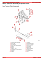
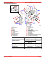
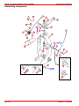
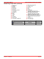
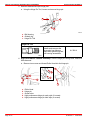
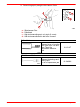
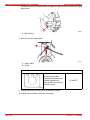
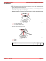
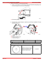
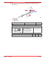
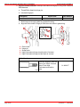
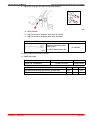
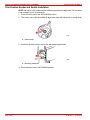
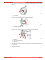
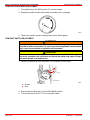
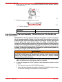
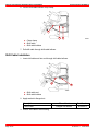
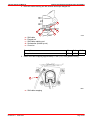
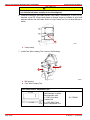
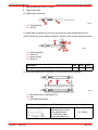
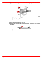
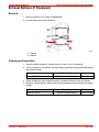
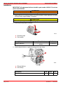
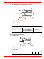
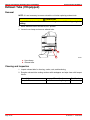
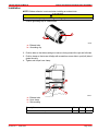
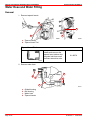
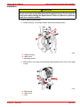
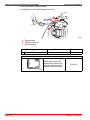
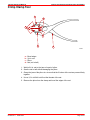
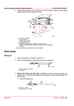
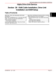
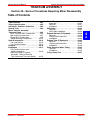
SERVICE PROCEDURES REQUIRING MINOR DIASSEMBLY
SERVICE MANUAL NUMBER 28
TRANSOM ASSEMBLY
Section 4A - Service Procedures Requiring Minor Disassembly
Table of Contents
Bravo Transom Assembly
Specifications . . . . . . . . . . . . . . . . . . . . . . . 4A-2
Torque Specifications . . . . . . . . . . . . . . . . 4A-2
Lubricants / Sealants / Adhesives . . . . . 4A-2
Special Tools . . . . . . . . . . . . . . . . . . . . . . . . 4A-3
Bravo Transom Assembly
Exploded Views . . . . . . . . . . . . . . . . . . . . . 4A-6
Inner Transom Plate Components . . . . 4A-6
Bell Housing Components . . . . . . . . . . . 4A-7
Gimbal Ring Components . . . . . . . . . . . . 4A-8
Gimbal Housing Components . . . . . . . 4A-10
Special Information . . . . . . . . . . . . . . . . . 4A-12
Trim Limit Switch . . . . . . . . . . . . . . . . . . 4A-12
Trim Position Sender . . . . . . . . . . . . . . . 4A-12
Removal . . . . . . . . . . . . . . . . . . . . . . . . . . . . 4A-12
Installation . . . . . . . . . . . . . . . . . . . . . . . . . 4A-17
Trim Position Sender and
Switch Installation . . . . . . . . . . . . . . . . . 4A-22
High Performance Transom
Assembly - Without Electrical
Trim Sender and Trim Limit Switch . . 4A-25
90-863160--1 JUNE 2003
Gimbal Bearing . . . . . . . . . . . . . . . . . . . . .
Inspection . . . . . . . . . . . . . . . . . . . . . . . .
Removal . . . . . . . . . . . . . . . . . . . . . . . . . .
Installation . . . . . . . . . . . . . . . . . . . . . . . .
Shift Cable . . . . . . . . . . . . . . . . . . . . . . . . . .
Removal . . . . . . . . . . . . . . . . . . . . . . . . . .
Shift Cable Installation . . . . . . . . . . . . . .
Exhaust Bellows (If Equipped) . . . . . . .
Removal . . . . . . . . . . . . . . . . . . . . . . . . . .
Cleaning and Inspection . . . . . . . . . . . .
Installation . . . . . . . . . . . . . . . . . . . . . . . .
Exhaust Tube (If Equipped) . . . . . . . . . .
Removal . . . . . . . . . . . . . . . . . . . . . . . . . .
Cleaning and Inspection . . . . . . . . . . . .
Installation . . . . . . . . . . . . . . . . . . . . . . . .
Water Hose and Water Fitting . . . . . . . .
Removal . . . . . . . . . . . . . . . . . . . . . . . . . .
Installation . . . . . . . . . . . . . . . . . . . . . . . .
Crimp Clamp Tool . . . . . . . . . . . . . . . . . . .
4A-26
4A-27
4A-27
4A-29
4A-33
4A-33
4A-34
4A-39
4A-39
4A-39
4A-40
4A-42
4A-42
4A-42
4A-43
4A-44
4A-44
4A-45
4A-47
Page 4A-1
4
A
SERVICE PROCEDURES REQUIRING MINOR DISASSEMBLY
SERVICE MANUAL NUMBER 28
Bravo Transom Assembly Specifications
Torque Specifications
NOTE: Securely tighten all fasteners not listed below.
Description
Nm
lb-in.
Shift cable core wire anchor screws
2.3
20
4
35
Exhaust bellows hose clamps
Hinge pins
203
Flanged nut
7
65
Trim wire retainer screw
11
95
lb-ft
150
Lubricants / Sealants / Adhesives
Description
Where Used
Part Number
U-joint bellows
Exhaust bellows
Bellows Adhesive
Bell housing side gear lube
valve O-ring
92-86166Q1
Shift cable bellows
Mounting surfaces on inside of
bellows
2 4 C with Teflon
2-4-C
Threads of tapered insert
Gimbal ring clamp screw
92 802859A1
92-802859A1
Flanged nut threads
Perfect Seal
Bayonet fitting
92-34227-1
Water bypass plug
Bell housing threads
Loctite 271 Threadlocker
Studs
92 809819
92-809819
Swivel shaft seal
Hinge pin washer inner surface
High Performance Gear Lube
Gear lube valve O-rings
92-802854A1
Sealer Kit, Two Part Epoxy
Bushings
92-65150-1
U-Joint and Gimbal Bearing
Grease
Gimbal bearing
92-802870A1
Super Glue
Soapy water or engine cleaner
Special Lubricant 101
Loctite 242 Threadlocker
Lacquer Thinner
Page 4A-2
Gimbal housing seal
Obtain locally
Exhaust passage seal
Sleeve outside diameter
Obtain locally
Hinge pin
92-802865Q 1
Threads Of Screw
Obtain locally
Exhaust Mounting Bellows
Obtain locally
90-863160--1 JUNE 2003
SERVICE PROCEDURES REQUIRING MINOR DIASSEMBLY
SERVICE MANUAL NUMBER 28
Special Tools
Retention Sleeve Removal Tool
78063
Use to remove the U-joint
bellows retention sleeve on
all the Bravo 2000 transom
assemblies.
Used also to remove the
aluminum sleeve from the
U-joint bellows of all Bravo
sterndrive units, Serial
Number 0L99999 and below.
91-862546
Installs and removes the
hinge pins from most all
Mercury MerCruiser
Transom units.
91-78310
Installs the aluminum sleeve
in the U-joint bellows of all
the Bravo sterndrive units.
91-818162
Installs and removes the
tapered insert retainer into
the water inlet hose on all
the Bravo transom units.
91-43579
Hinge Pin Tool
73443
Sleeve Installation Tool
73485
Tapered Insert Tool
73456
90-863160--1 JUNE 2003
Page 4A-3
SERVICE PROCEDURES REQUIRING MINOR DISASSEMBLY
SERVICE MANUAL NUMBER 28
Special Tools (continued)
Bellows Expander Tool
73430
Installs the exhaust bellows
on the Bravo One, Bravo
Two, and Bravo Three
Transom units.
91-45497A1
Removes the bearings and
bearing cups.
91-34570 Replacement Jaw
91-34569A1
Slide Hammer Puller
73655
Clamp Plate
Holds a preload while
checking the backlash and
bearing preload on all
Mercury MerCruiser Bravo
sterndrive units.
91-43559T
73433
Shift Cable Anchor Adjustment Tool
91-17262
91-17263
Page 4A-4
73478
Used when installing a new
Shift Cable Core wire in all
Bravo Transoms.
91-17263 Core Wire
Locating Tool
91-17262 Shift Cable
Anchor Adjustment Tool
91-17262A1
90-863160--1 JUNE 2003
SERVICE PROCEDURES REQUIRING MINOR DIASSEMBLY
SERVICE MANUAL NUMBER 28
Special Tools (continued)
Bearing Removal and Installation Tool Assembly
70615
90-863160--1 JUNE 2003
Installs and removes the
bearings on all Alpha and
Bravo sterndrive gear cases.
91-31229A7 tool assembly
includes the following
components:
11-24156 Hex Nut
91-15755T Bearing Carrier
91-29310 Plate
91-29610 Pilot Plate
91-30366T1 Mandrel
91-31229 Puller Shaft
91-32325T Driver Head
91-32336 Driver Needle
Bearing
12-34961 Washer
91-36379 Puller / Head Gear
91-36569T Driver Head
91-36571T Pilot Washer
91-37292 Roller Bearing
91-37311 Driver Head
91-37312 Driver Head
91-37323 Driver Head Rod
91-37324 Pilot Washer
91-38628T Puller / Driver
Head
91-52393 Driver Needle
Bearing
91-52394 Head Pull Rod
91-31229A7
Page 4A-5
SERVICE PROCEDURES REQUIRING MINOR DISASSEMBLY
SERVICE MANUAL NUMBER 28
Bravo Transom Assembly Exploded Views
Inner Transom Plate Components
4
1
5
6
7
8
9
3
2
10 11
3
2
14
13
15
16
17
12
19
20
1 - Transom plate assembly
2 - Pivot bolts
3 - Tab washers
4 - Rear engine mounting bolt
5 - Washer
6 - Spacer
7 - Washer - fiber
8 - Lockwasher - double wound
9 - Locknut
10 - Washer
Page 4A-6
76857
18
11 - Locknut
12 - Shift cable casing
13 - Core wire anchor
14 - Set screws (2)
15 - End guide
16 - Nylon tube
17 - Nylon wrapping
18 - Core wire
19 - Sealing washer
20 - Nut
90-863160--1 JUNE 2003
SERVICE PROCEDURES REQUIRING MINOR DIASSEMBLY
SERVICE MANUAL NUMBER 28
Bell Housing Components
16
20
10
17
D
9
A
18
A
1
75258
13
2
3
4
12
11
11
6
11
14
8
7
C
B
5
19
13
E
15
A
76627
1 - Bell housing
2 - Stud
3 - Washer
4 - Locknut
5 - O-ring
6 - Gear lube valve
7 - O-rings
8 - Hinge pin washer
9 - Bellows clamp
10 - U-joint bellows
Description
11 - Grounding clip
12 - Sleeve
13 - Bellows clamp
14 - Exhaust bellows
15 - Exhaust tube (some models)
16 - Lube monitor hose
17 - Hose clamp
18 - Bayonet fitting
19 - Bushing (High Performance transom)
20 - Indentations in bell housing
Where Used
Part Number
U-joint bellows
A Bellows Adhesive
B Loctite 271 Threadlocker
C High Performance Gear Lube
D Perfect Seal
E Sealer Kit, Two Part Epoxy
90-863160--1 JUNE 2003
Exhaust bellows
Bell housing side gear lube
valve O-ring
92-86166Q1
HIng pin washer inner surface
92-809819
Gear lube valve O-rings
92-802854A1
Bayonet fitting
92-34227-1
Bushing
92-65150-1
Page 4A-7
SERVICE PROCEDURES REQUIRING MINOR DISASSEMBLY
SERVICE MANUAL NUMBER 28
Gimbal Ring Components
21
19
20
26
15
10
17
8
9
27
7
B
18
10
16
1
11
12
3
A
5
13
4
8
14
6
2
9
7
22
75252
A
25
24
75272
23
76618
Page 4A-8
90-863160--1 JUNE 2003
SERVICE MANUAL NUMBER 28
SERVICE PROCEDURES REQUIRING MINOR DIASSEMBLY
Gimbal Ring Components (continued)
1 - Gimbal ring
2 - Bushing
3 - Bushing
4 - Flat washer
5 - Hinge pin
6 - Trim position sender
7 - Flat washer
8 - Lockwasher
9 - Screw
10 - Clip
11 - U-Bolt
12 - Plate
13 - Locknuts
14 - Swivel shaft
15 - Flat washer (smaller ID)
Description
A Sealer Kit, Two Part Epoxy
B 2-4-C with Teflon
90-863160--1 JUNE 2003
16 - Flat washer (larger ID)
17 - Clamp screw
18 - Locknut
19 - Nut
20 - Screw
21 - Clamp plate
22 - High Performance hinge pin
assembly (early style) (2 screws)
23 - High Performance hinge pin
assembly (later style) (4 screws)
24 - Magnum and High Performance
gimbal ring identification (filled area)
25 - Standard gimbal ring identification
(2 ribs)
26 - Steering lever
27 - Trim limit switch
Where Used
Part Number
Bushings
92-65150-1
Gimbal ring clamp screw
92-802859A1
Page 4A-9
SERVICE PROCEDURES REQUIRING MINOR DISASSEMBLY
SERVICE MANUAL NUMBER 28
Gimbal Housing Components
37 38
36
8
6
10
35
6
7
9
3
5
E
A
7
2
11 12
13
D
4
33
1
C
15
34
32
14
31
16
29
28
19
A
29
D
30
23
B
22
20
17
Page 4A-10
18
21
25
26
24
27
76642
90-863160--1 JUNE 2003
SERVICE PROCEDURES REQUIRING MINOR DIASSEMBLY
SERVICE MANUAL NUMBER 28
Gimbal Housing Components (continued)
1 - Gimbal housing
2 - Stud
3 - Swivel shaft bushing (lower)
4 - Swivel shaft seal
5 - Swivel shaft bushing (upper)
6 - Clamp
7 - Lube monitor hose
8 - Quick disconnect fitting
9 - E-Clip
10 - Gear lube fitting
11 - Water bypass plug
12 - Flat washer
13 - Locknut
14 - Seal
15 - Gimbal bearing
16 - Tolerance ring
17 - Crimp clamp
18 - Shift cable bellows
19 - Bellows clamp
Description
A Loctite 271 Threadlocker
B Bellows Adhesive
C
U-joint and Gimbal Bearing
Grease
D Super Glue
E Perfect Seal
90-863160--1 JUNE 2003
20 - Washer
21 - Lower swivel pin
22 - Cotter pin
23 - Stud
24 - Gasket
25 - Hydraulic manifold
26 - Washer
27 - Locknut
28 - Exhaust passage seal
29 - Water hose insert
30 - Water hose
31 - Water fitting gasket
32 - Water fitting
33 - Lockwasher
34 - Screw
35 - Gimbal housing seal
36 - Large O-rings
37 - Snap ring groove
38 - Small O-ring
Where Used
Studs
Swivel shaft seal
Part Number
92 809819
92-809819
Shift cable bellows
92-86166Q1
Gimbal bearing
92-802870A1
Gimbal housing seal
Exhaust passage seal
Water bypass plug
Obtain locally
92-34227-1
Page 4A-11
SERVICE PROCEDURES REQUIRING MINOR DISASSEMBLY
SERVICE MANUAL NUMBER 28
Special Information
Trim Limit Switch
The trim limit switch has a sealing system for improved water resistance and durability. The
trim limit switch leads are connected internally to help ensure good electrical integrity.
71415
Trim limit switch - port
Trim Position Sender
The trim position sender has a sealing system for improved water resistance and durability.
The trim limit leads are connected internally to help ensure good electrical integrity.
71414
Trim position sender - starboard
Removal
WARNING
Disconnect both battery cables before installing new trim limit switch or trim
sender.
1. Remove sterndrive unit. Refer to Section 2A.
2. Remove trim limit switch.
a
71221
Page 4A-12
90-863160--1 JUNE 2003
SERVICE PROCEDURES REQUIRING MINOR DIASSEMBLY
SERVICE MANUAL NUMBER 28
a - Attaching hardware
3. Remove trim position sender.
a
71220
a - Attaching hardware
4. Spray engine cleaner around edge of bellows sleeve and remove with Retention Sleeve
Removal Tool.
c
a
b
b
71527
a - Sleeve
b - Retention Sleeve Removal Tool
c - Bell housing
Retention Sleeve Removal Tool
78063
90-863160--1 JUNE 2003
Use to remove the U-joint
bellows retention sleeve on
all the Bravo 2000 transom
assemblies.
Used also to remove the
aluminum sleeve from the
U-joint bellows of all Bravo
sterndrive units, Serial
Number 0L99999 and below.
91-862546
Page 4A-13
SERVICE PROCEDURES REQUIRING MINOR DISASSEMBLY
SERVICE MANUAL NUMBER 28
5. Remove starboard and port hinge pins.
a. Using the Hinge Pin Tool, loosen and remove hinge pin.
a
c
b
22113
a - Bell housing
b - Gimbal ring
c - Hinge Pin Tool
Hinge Pin Tool
Installs and removes the
hinge pins from Mercury
MerCruiser gimbal ring and
bell housing assemblies.
91-78310
73443
6. High Performance Transom Assembly: Remove hinge pins using Puller Head and
Slide Hammer.
a. Remove torx screws and thread Puller Head into the hinge pin.
b
d
c
b
c
a
b
c
d
e
Page 4A-14
e
a
- Puller Head
- Hinge pin
- Screw holes
- High performance hinge pin early style (2 screws)
- High performance hinge pin later style (4 screws)
90-863160--1 JUNE 2003
SERVICE PROCEDURES REQUIRING MINOR DIASSEMBLY
SERVICE MANUAL NUMBER 28
b. Remove hinge pin by using the Slide Hammer Puller.
b
c
d
a
71826
a
b
c
d
- Slide Hammer Puller
- Puller Head
- High Performance hinge pin early style (2 screws)
- High Performance hinge pin later style (4 screws)
Puller Head
73428
Removes hinge pin from the
Bravo One, Bravo Two and
Bravo Three High
Performance sterndrive
units.
91-63616T
Removes the bearings and
bearing cups.
91-34570 Replacement jaw
91-34569A1
Slide Hammer Puller
73655
90-863160--1 JUNE 2003
Page 4A-15
SERVICE PROCEDURES REQUIRING MINOR DISASSEMBLY
SERVICE MANUAL NUMBER 28
7. Pull back on bell housing and rotate it 90 degrees to gain access to the trim wire clamp
plate screw.
a
23363
a - Bell housing
8. Remove trim wire clamp plate.
a
b
70197
a - Clamp Plate
b - Screw
Clamp Plate
Holds a preload while
checking the backlash and
bearing preload on all
Mercury MerCruiser Bravo
sterndrive units.
91-43559T
73433
9. Unplug trim position sender wires from engine harness.
10. Unplug trim limit switch wires from trim pump.
Page 4A-16
90-863160--1 JUNE 2003
SERVICE PROCEDURES REQUIRING MINOR DIASSEMBLY
SERVICE MANUAL NUMBER 28
Installation
NOTE: Old harness may be used to pilot new harnesses through hole in gimbal housing.
1. Route new sender wires through hole.
2. Bring together the two grommet halves and ensure that they are seated lightly in the hole
with the flat mating edges vertically aligned.
3. Maintain light tension on the wires from inside the boat to hold the grommets in the hole.
b
a
70198
a - Trim limit switch wires
b - Trim position sender wires
4. Reinstall retainer and torque screw.
a
b
70197
a - Clamp
b - Screw
90-863160--1 JUNE 2003
Description
Nm
lb-in.
Shift cable core wire retainer screw
11
95
lb-ft
Page 4A-17
SERVICE PROCEDURES REQUIRING MINOR DISASSEMBLY
SERVICE MANUAL NUMBER 28
5. Install U-joint bellows on bell housing as follows:
a. Position U-joint bellows on bell housing. Ensure that the bell housing flange rests
in the second groove from the end of the bellows.
a
22116
a - Bell housing flange
b. Lubricate sleeve outside diameter. Install sleeve with Sleeve Installation Tool and
a suitable driving rod.
a
b
A
c
76670
76671
a - Sleeve
b - Sleeve Installation Tool
c - Suitable driving rod
Description
A Soapy water or engine cleaner
Where Used
Part Number
Sleeve outside diameter
Obtain locally
Sleeve Installation Tool
Installs the aluminum sleeve
in the U-joint bellows of all
the Bravo transom units.
91-818162
73485
Page 4A-18
90-863160--1 JUNE 2003
SERVICE PROCEDURES REQUIRING MINOR DIASSEMBLY
SERVICE MANUAL NUMBER 28
6. Apply sealant to bell housing threads and install port and starboard hinge pins.
7. Torque hinge pins.
a
c
A
b
76619
a - Bell housing
b - Gimbal ring
c - Hinge Pin Tool
Description
A Loctite 271 Threadlocker
Where Used
Part Number
Bell housing threads
92-809819
Hinge Pin Tool
Installs and removes the
hinge pins from Mercury
MerCruiser gimbal ring and
bell housing assemblies.
91-78310
73443
90-863160--1 JUNE 2003
Description
Nm
Hinge pins
203
lb-in.
lb-ft
150
Page 4A-19
SERVICE PROCEDURES REQUIRING MINOR DISASSEMBLY
SERVICE MANUAL NUMBER 28
8. High Performance Models: Install port and starboard hinge pins using Puller Head and
Slide Hammer.
a. Thread Puller Head into hinge pin.
b. Lubricate hinge pin.
Description
Where Used
Part Number
Hinge pin
92-802865Q 1
Special Lubricant 101
c. Slide hinge pin through gimbal ring and bell housing.
d. Align the screw holes in hinge pin with the screw holes in gimbal ring.
c
b
d
e
a
a
b
c
d
e
c
79264
- Puller Head
- Hinge pin
- Screw holes
- High Performance hinge pin early style (2 screws)
- High Performance hinge pin later style (4 screws)
Puller Head
73428
Page 4A-20
Removes hinge pin from the
Bravo One, Bravo Two and
Bravo Three High
Performance sterndrive
units.
91-63616T
90-863160--1 JUNE 2003
SERVICE PROCEDURES REQUIRING MINOR DIASSEMBLY
SERVICE MANUAL NUMBER 28
9. Lightly tap hinge pin into place using Slide Hammer.
b
c
a
71826
a - Slide Hammer
b - High Performance hinge pin early style (2 screws)
c - High Performance hinge pin later style (4 screws)
Slide Hammer Puller
73655
Removes the bearings and
bearing cups.
91-34570 Replacement Jaw
91-34569A1
10. Apply sealant to threads of screws.
11. Install and torque.
Description
Loctite 242 Threadlocker
90-863160--1 JUNE 2003
Where Used
Part Number
Threads Of Screw
Obtain locally
Description
Nm
High performance hinge pin screws (2) early style
203
High performance hinge pin screws (4) later style
3
lb-in.
lb-ft
150
27
Page 4A-21
SERVICE PROCEDURES REQUIRING MINOR DISASSEMBLY
SERVICE MANUAL NUMBER 28
Trim Position Sender and Switch Installation
NOTE: 496 cid (8.1 liter) models require a different procedure for adjustment This procedure
is not available at time of publication.
1. Place sterndrive unit in the full DOWN/IN position.
2. Turn center rotor of trim limit switch to align index mark with index mark on sender body.
a
71218
a - Index marks
3. Install trim position sender and secure with attaching hardware.
a
71220
a - Attaching hardware
4. Place sterndrive unit in full DOWN/IN position.
Page 4A-22
90-863160--1 JUNE 2003
SERVICE PROCEDURES REQUIRING MINOR DIASSEMBLY
SERVICE MANUAL NUMBER 28
5. Turn center rotor of trim position sender to align index mark with index mark on sender
body.
a
71218
a - Index marks
6. Install trim limit switch and secure with attaching hardware.
a
71221
a - Attaching hardware
7. Secure the trim limit switch harness to the water hose with the plastic clip.
b
a
c
71184
a - Plastic clip
b - Trim limit switch harness
c - Water hose
8. Reconnect trim position sender wires to engine harness and the trim limit leads to trim
pump harness.
9. Reinstall battery cables.
90-863160--1 JUNE 2003
Page 4A-23
SERVICE PROCEDURES REQUIRING MINOR DISASSEMBLY
SERVICE MANUAL NUMBER 28
TRIM POSITION SENDER ADJUSTMENT
1. Turn ignition key to the RUN position. Do not start engine.
2. Rotate trim position sender until needle is at bottom of arc on gauge.
22175
3. Tighten trim position sender retaining screws and recheck gauge.
TRIM LIMIT SWITCH ADJUSTMENT
WARNING
When adjusting trim limit switch, use extreme care that engine is not started and
keep clear of area near propeller. Use care to prevent placing hands in an area where
injury could occur because of sterndrive unit movement.
CAUTION
Trim limit switch must be adjusted exactly as outlined. If switch is adjusted
incorrectly, sterndrive unit could move out beyond the gimbal ring support flanges
and cause damage to sterndrive unit.
1. Loosen screws and turn trim limit switch CLOCKWISE to end of slots.
a
b
71221
a - Screws
b - Slots
2. Ensure that sterndrive unit is in the full DOWN/IN position.
3. Trim sterndrive unit UP/OUT. Do not use trailer switch.
Page 4A-24
90-863160--1 JUNE 2003
SERVICE PROCEDURES REQUIRING MINOR DIASSEMBLY
SERVICE MANUAL NUMBER 28
4. Slowly turn trim limit switch COUNTERCLOCKWISE until trim cylinders extend to
correct dimension.
71221
5. Retighten screws when adjustment is correct.
a
50464
a - Trim limit dimension
Description
Trim limit dimension
552 mm (21-3/4 in.)
High Performance Transom Assembly - Without Electrical Trim Sender and
Trim Limit Switch
IMPORTANT: The electrical trim limit switch and trim position sender are not present
on this transom assembly. Without a trim limit switch, the sterndrive unit can be
trimmed UP/OUT beyond the position where the sterndrive unit has side support
from the gimbal ring at any throttle setting. It is highly recommended that a
mechanical (cable actuated) trim position indicator be installed to provide important
sterndrive unit trim angle information to the operator and that the trim indicator be
marked to clearly indicate the maximum UP/OUT position where side support is still
provided. The sterndrive unit should not be trimmed to a position beyond gimbal ring
side support at engine speeds above 1200 rpm.
WARNING
Avoid personal injury or damage to sterndrive unit. Do not trim sterndrive unit to
an UP/OUT position where the sterndrive unit receives no side support from the
gimbal ring at engine speeds above 1200 rpm. Refer to a properly marked
mechanical trim position indicator.
1. Install WARNING DECAL (contained in the transom assembly box) at the operator
station in a place where it will be clearly visible to the operator.
2. To mark the maximum trim UP/OUT position on the mechanical trim indicator, proceed
as follows:
a. Trim sterndrive units to the FULL DOWN/IN position.
b. Ensure that the mechanical trim indicator indicates FULL DOWN/IN position. Adjust
the indicator following the manufacturers recommendations.
90-863160--1 JUNE 2003
Page 4A-25
SERVICE PROCEDURES REQUIRING MINOR DISASSEMBLY
SERVICE MANUAL NUMBER 28
c. Slowly raise the sterndrive units until the trim limit point is reached. The trim limit
point can be determined by measuring the amount of trim cylinder extension. The
dimension for the Bravo sterndrive units is measured from front anchor point to rear
anchor point centerlines as shown following.
a
50464
a - Trim limit dimension
Description
Trim limit dimension
552 mm (21-3/4 in.)
3. With the trim cylinders at this position, place a mark on the mechanical trim indicator in
console.
a. Raise and lower sterndrive units several times to ensure that the trim limit point is
properly marked.
Gimbal Bearing
IMPORTANT: Gimbal bearing and carrier are a matched set and must be replaced as
an assembly. Tolerance ring must be replaced any time gimbal bearing is removed.
NOTE: The gimbal bearing inner race thickness has changed to accommodate the larger
U-joint used in the X, XZ, and XR Bravo sterndrive units. If an X, XZ, or XR sterndrive unit
is installed on a transom with the thicker gimbal bearing, interference will occur between the
U-joint and the bearing. Either one or both components will fail. The new gimbal bearing can
be identified by a red dot.
d
b
a
c
76666
New
a
b
c
d
Old
- 9.47 cm (3.73 in.)
- 2.05 cm (0.81 in.)
- 9.37 cm (3.69 in.)
- 2.54 cm (1.00 in.)
a
79222
a - Red dot
Page 4A-26
90-863160--1 JUNE 2003
SERVICE PROCEDURES REQUIRING MINOR DIASSEMBLY
SERVICE MANUAL NUMBER 28
Inspection
1. Remove sterndrive unit.
2. Reach through bell housing. Rotate gimbal bearing and check for rough spots. Pull and
push on inner race to check for side wear. Any excessive movement or roughness is
cause for replacement.
Removal
CAUTION
Do not remove gimbal bearing unless replacement is necessary, as damage to
bearing may result during removal.
1. Remove gimbal bearing assembly.
d
b
a
c
a
b
c
d
e
f
g
e
f
g
76658
- Puller shaft
- Nut
- Washer
- Plates (3)
- Slide Hammer Puller
- Gimbal bearing inner race
- Gimbal bearing carrier
NOTE: Plate Puller included in Bearing Removal and Installation Tool Assembly part
number 91-31339A7.
90-863160--1 JUNE 2003
Page 4A-27
SERVICE PROCEDURES REQUIRING MINOR DISASSEMBLY
SERVICE MANUAL NUMBER 28
Bearing Removal and Installation Tool Assembly
70615
Installs and removes the
bearings on all Alpha and
Bravo sterndrive gear cases.
91-31229A7 tool assembly
includes the following
components:
11-24156 Hex Nut
91-15755T Bearing Carrier
91-29310 Plate
91-29610 Pilot Plate
91-30366T1 Mandrel
91-31229 Puller Shaft
91-32325T Driver Head
91-32336 Driver Needle
Bearing
12-34961 Washer
91-36379 Puller / Head Gear
91-36569T Driver Head
91-36571T Pilot Washer
91-37292 Roller Bearing
91-37311 Driver Head
91-37312 Driver Head
91-37323 Driver Head Rod
91-37324 Pilot Washer
91-38628T Puller / Driver
Head
91-52393 Driver Needle
Bearing
91-52394 Head Pull Rod
91-31229A7
Removes the bearings and
bearing cups.
91-34570 Replacement Jaw
91-34569A1
Slide Hammer Puller
73655
Page 4A-28
90-863160--1 JUNE 2003
SERVICE PROCEDURES REQUIRING MINOR DIASSEMBLY
SERVICE MANUAL NUMBER 28
2. Remove grease seal using a Slide Hammer Puller.
a
b
22171
a - Gimbal housing
b - Grease seal
Slide Hammer Puller
73655
Removes the bearings and
bearing cups.
91-34570 Replacement Jaw
91-34569A1
Installation
1. Install grease seal using a suitable mandrel.
NOTE: The seal should be installed with the open face of the seal towards the gimbal
bearing.
a
b
22171
a - Gimbal housing
b - Grease seal
90-863160--1 JUNE 2003
Page 4A-29
SERVICE PROCEDURES REQUIRING MINOR DISASSEMBLY
SERVICE MANUAL NUMBER 28
2. Install and position new tolerance ring.
a
b
d
c
22159
a
b
c
d
- Carrier
- Carrier grease hole
- Tolerance ring
- Opening in tolerance ring
3. Align opening in tolerance ring with grease hole in gimbal bearing cartridge.
IMPORTANT: Red dot on gimbal bearing must be positioned at 10 o’clock portside.
IMPORTANT: Ensure that notched edge of bearing carrier faces inward in bore.
4. Align gimbal bearing carrier grease hole and tolerance ring opening with grease cavity
hole in gimbal housing.
a
c
b
76559
a - Gimbal bearing carrier grease hole
b - Tolerance ring opening
c - Bearing carrier notch
Page 4A-30
90-863160--1 JUNE 2003
SERVICE PROCEDURES REQUIRING MINOR DIASSEMBLY
SERVICE MANUAL NUMBER 28
5. Install gimbal bearing with the red dot facing out toward the drive end using a brass
hammer and tools shown. Ensure that the gimbal bearing carrier contacts gimbal
housing.
e
a
b
c
d
f
22118
a
b
c
d
e
f
90-863160--1 JUNE 2003
- Drive Rod
- Plate
- Puller / Driver Head
- Mandrel
- Gimbal bearing assembly (red dot facing out)
- Chamfer
Page 4A-31
SERVICE PROCEDURES REQUIRING MINOR DISASSEMBLY
SERVICE MANUAL NUMBER 28
Bearing Removal and Installation Tool Assembly
70615
Page 4A-32
Installs and removes the
bearings on all Alpha and
Bravo sterndrive gear cases.
91-31229A7 tool assembly
includes the following
components:
11-24156 Hex Nut
91-15755T Bearing Carrier
91-29310 Plate
91-29610 Pilot Plate
91-30366T1 Mandrel
91-31229 Puller Shaft
91-32325T Driver Head
91-32336 Driver Needle
Bearing
12-34961 Washer
91-36379 Puller / Head Gear
91-36569T Driver Head
91-36571T Pilot Washer
91-37292 Roller Bearing
91-37311 Driver Head
91-37312 Driver Head
91-37323 Driver Head Rod
91-37324 Pilot Washer
91-38628T Puller / Driver
Head
91-52393 Driver Needle
Bearing
91-52394 Head Pull Rod
91-31229A7
90-863160--1 JUNE 2003
SERVICE PROCEDURES REQUIRING MINOR DIASSEMBLY
SERVICE MANUAL NUMBER 28
Shift Cable
Removal
1. Remove sterndrive unit. Refer to Section 2A.
2. Disconnect shift cable from shift plate and remove end guide.
b
a
22183
a - Anchor screws (2) - loosen
b - End guide
3. Hold shift cable retaining nut with wrench.
4. Remove flanged nut.
c
b
a
76673
a - Shift cable retaining nut
b - Seal washer
c - Flanged nut
5. Remove shift cable wrapping.
a
76639
a - Shift cable wrapping
90-863160--1 JUNE 2003
Page 4A-33
SERVICE PROCEDURES REQUIRING MINOR DISASSEMBLY
SERVICE MANUAL NUMBER 28
6. Loosen shift cable bellows crimp clamp.
b
a
c
50458
a - Crimp clamp
b - Shift cable
c - Shift cable bellows
7. Pull shift cable through shift cable bellows.
Shift Cable Installation
1. Insert shift cable end into and through shift cable bellows.
a
b
76620
a - Shift cable end
b - Shift cable bellows
2. Apply sealant to flanged nut.
Description
Where Used
Part Number
Perfect Seal
Flanged nut threads
92-34227-1
3. Secure shift cable to bell housing.
Page 4A-34
90-863160--1 JUNE 2003
SERVICE PROCEDURES REQUIRING MINOR DIASSEMBLY
SERVICE MANUAL NUMBER 28
4. Hold shift cable retaining nut with wrench and torque flanged nut.
d
a
e
b
a
b
c
d
e
c
50327
- Shift cable
- Flanged nut
- Shift cable retaining nut
- Seal washer (hidden by nut)
- Core wire
Description
Nm
lb-in.
Flanged nut
7
65
lb-ft
5. Install shift cable wrapping approximately 51 mm (2 in.) from gimbal housing.
a
76639
a - Shift cable wrapping
90-863160--1 JUNE 2003
Page 4A-35
SERVICE PROCEDURES REQUIRING MINOR DISASSEMBLY
SERVICE MANUAL NUMBER 28
CAUTION
Water leakage may result if clamp is not installed properly. Ensure that bellows end
is not flattened out when crimping in the followIng step.
6. Install and compress shift cable bellows crimp clamp, maintaining a 13 mm (1/2 in.)
diameter round OD. Ensure that clamp is crimped evenly to maintain a good seal
between bellows and shift cable. Refer to Crimp Clamp Tool. Do not allow bellows to
flatten.
a
22117
a - Crimp clamp
7. Install Core Wire Locating Tool on face of bell housing.
a
b
50327
a - Bell housing
b - Core Wire Locating Tool
Shift Cable Anchor Adjustment Tool
91-17262
91-17263
Page 4A-36
73478
Installs and removes shift
shaft bushings on all the
Bravo transom units.
91-17263 Core Wire
Locating Tool
91-17262 Shift Cable
Anchor Adjustment Tool
91-17262A1
90-863160--1 JUNE 2003
SERVICE PROCEDURES REQUIRING MINOR DIASSEMBLY
SERVICE MANUAL NUMBER 28
8. Install threaded tube until it contacts.
9. Tighten finger-tight.
10. Tighten jam nut securely.
a
b
22183
a - Threaded tube
b - Jam nut
11. Install cable end guide over core wire and insert core wire through cable anchor.
12. Ensure that core wire is visible in sight port. Tighten anchor screws evenly and torque.
a
d
c
a
b
c
d
c
79263
b d
- Cable end guide
- Core wire
- Anchor screws
- Sight port
Description
Nm
lb-in.
Steering cable anchor screws
2.3
20
lb-ft
13. Place Shift Cable Anchor Adjustment Tool on the end of the shift cable.
c
a
b
22120
a - Shift Cable Anchor Adjustment Tool
b - Stud
c - Hole barrel placed here
Shift Cable Anchor Adjustment Tool
91-17262
91-17263
90-863160--1 JUNE 2003
73478
Installs and removes shift
shaft bushings on all the
Bravo transom units.
91-17262 Shift Cable
Anchor Adjustment Tool
91-17262A1
Page 4A-37
SERVICE PROCEDURES REQUIRING MINOR DISASSEMBLY
SERVICE MANUAL NUMBER 28
14. Ensure that bell housing end of core wire is positioned tight against Core Wire Locating
Tool.
a
c
b
22121
a - Bell housing
b - Core Wire Locating Tool
c - Core wire
15. Adjust cable barrel to align with hole in tool.
16. Remove tools and install cable on shift plate assembly, being careful not to move the
adjustment.
a
b
22120
a - Barrel
b - Hole in tool
Page 4A-38
90-863160--1 JUNE 2003
SERVICE PROCEDURES REQUIRING MINOR DIASSEMBLY
SERVICE MANUAL NUMBER 28
Exhaust Bellows (If Equipped)
Removal
1. Remove sterndrive unit. Refer to Section 2A.
2. Loosen clamps and remove bellows.
a
a
b
22116
a - Clamps
b - Bellows
Cleaning and Inspection
1. Inspect exhaust bellows for internal charring, cracks, cuts, or hardening.
2. Clean old adhesive from bellows mounting flange on gimbal housing and on bell housing
with lacquer thinner.
Description
Lacquer Thinner
Where Used
Part Number
Bellows mounting flange
Obtain Locally
3. Clean old adhesive from mounting surface of exhaust bellows if using old bellows.
4. Roughen exhaust bellows mating surfaces with sandpaper and wipe clean with lacquer
thinner.
Description
Lacquer Thinner
90-863160--1 JUNE 2003
Where Used
Part Number
Bellows mounting flange
Obtain Locally
Page 4A-39
SERVICE PROCEDURES REQUIRING MINOR DISASSEMBLY
SERVICE MANUAL NUMBER 28
Installation
IMPORTANT: All replacement bellows should be part number 18654A1. Do not use
earlier model bellows.
WARNING
Be sure to follow label directions when using Bellows Adhesive.
1. Apply adhesive to mounting surfaces on inside of bellows. Allow adhesive to dry until
no longer tacky (approximately 10 minutes).
CAUTION
Bellows clamps may corrode if grounding clips are not installed.
2. Position grounding clips on bellows.
a
b
22079
a - Grounding clips
b - Part number
Description
Bellows Adhesive
Where Used
Part Number
Mounting surfaces on inside of
bellows
92-86166Q1
3. Install exhaust bellows on gimbal housing and torque clamp.
b
a
76660
a - Exhaust bellows
b - Hose clamp
Description
Exhaust bellows hose clamp
Page 4A-40
Nm
lb-in.
4
35
lb-ft
90-863160--1 JUNE 2003
SERVICE PROCEDURES REQUIRING MINOR DIASSEMBLY
SERVICE MANUAL NUMBER 28
4. Place hose clamp over bellows end.
5. Place Bellows Expander Tool into first bellows convolution.
6. Pull tool until tool touches the flange on bell housing (bellows starts to slip onto flange)
and then release tool.
a
c
d
b
a
b
c
d
22116
- Bellows Expander Tool
- Bell housing flange
- Exhaust bellows
- Hose clamp
Bellows Expander Tool
Installs the exhaust bellows
on the Bravo One, and
Bravo Two sterndrive units.
91-45497A1
73430
7. Reposition tool into the third bellows convolution.
8. Pull bellows onto bell housing flange.
9. Torque hose clamp.
b
c
a
22116
a - Exhaust bellows
b - Bell housing flange
c - Hose clamp
Description
Exhaust bellows hose clamp
90-863160--1 JUNE 2003
Nm
lb-in.
4
35
lb-ft
Page 4A-41
SERVICE PROCEDURES REQUIRING MINOR DISASSEMBLY
SERVICE MANUAL NUMBER 28
Exhaust Tube (If Equipped)
Removal
NOTE: It is not necessary to remove sterndrive unit when replacing exhaust tube.
CAUTION
Support aft end of sterndrive unit when working between bell housing and gimbal
housing.
1. Raise sterndrive unit to the full UP/OUT position.
2. Loosen hose clamp and remove exhaust tube.
a
b
22184
a - Hose clamp
b - Exhaust tube
Cleaning and Inspection
1. Inspect exhaust tube for charring, cracks, cuts, and hardening.
2. Roughen exhaust tube mating surfaces with sandpaper and wipe clean with lacquer
thinner.
Description
Lacquer Thinner
Page 4A-42
Where Used
Part Number
Bellows mounting flange
Obtain Locally
90-863160--1 JUNE 2003
SERVICE PROCEDURES REQUIRING MINOR DIASSEMBLY
SERVICE MANUAL NUMBER 28
Installation
NOTE: Bellows adhesive is not used when installing an exhaust tube.
CAUTION
Exhaust tube clamp may corrode if grounding clip is not installed.
1. Position grounding clip on exhaust tube.
b
a
22184
a - Exhaust tube
b - Grounding clip
2. Position tube so that side markings on tube are facing toward the right and left sides.
3. Position clamp so that screw will align with screwdriver access hole in port (left) side of
gimbal housing.
4. Tighten and torque hose clamp.
b
c
a
22184
a - Exhaust tube
b - Hose clamp
c - Side marking
Description
Exhaust tube hose clamp
90-863160--1 JUNE 2003
Nm
lb-in.
4
35
lb-ft
Page 4A-43
SERVICE PROCEDURES REQUIRING MINOR DISASSEMBLY
SERVICE MANUAL NUMBER 28
Water Hose and Water Fitting
Removal
1. Remove tapered inserts.
a
a
b
b
22080
50322
a - Tapered inserts
b - Tapered Insert Tool
Tapered Insert Tool
Installs and removes the
tapered insert retainer into
the water inlet hose on all
the Bravo sterndrive units.
91-43579
73456
2. Remove water hose.
d
b
a
d
c
22101
a
b
c
d
Page 4A-44
- Gimbal housing
- Bell housing
- Water hose
- Tapered inserts
90-863160--1 JUNE 2003
SERVICE PROCEDURES REQUIRING MINOR DIASSEMBLY
SERVICE MANUAL NUMBER 28
Installation
CAUTION
The water hose in the following step is a preformed hose and must be installed with
the short end of the molded hose going into the gimbal housing. The hose must be
held in place while installing the tapered inserts. Failure to hold hose in place can
result in an overheat condition.
1. Position water hose as follows:
a. Gimbal Housing - hose edge must be flush with mounting surface.
c
b
a
22080
a - Gimbal housing
b - Water hose
c - Mounting surface
b. Bell Housing - hose edge should protrude approximately 3 mm (1/8 in.) from edge
of hole.
b
a
c
50322
a - Bell housing
b - Water hose
c - Hole
90-863160--1 JUNE 2003
Page 4A-45
SERVICE PROCEDURES REQUIRING MINOR DISASSEMBLY
SERVICE MANUAL NUMBER 28
2. Lubricate threads of tapered inserts.
3. Install tapered inserts with Tapered Insert Tool.
b
A
c
a
75962
a - Tapered insert
b - Tapered Insert Tool
c - Gimbal housing
Description
A 2-4-C with Teflon
Where Used
Part Number
Threads of tapered insert
92-802859A1
Tapered Insert Tool
Installs and removes the
tapered insert retainer into
the water inlet hose on all
the Bravo sterndrive units.
91-43579
73456
Page 4A-46
90-863160--1 JUNE 2003
SERVICE PROCEDURES REQUIRING MINOR DIASSEMBLY
SERVICE MANUAL NUMBER 28
Crimp Clamp Tool
b
a
a
d
d
a
b
c
74148
a
b
c
d
- Bevel edges
- 3/4 in. nut
- Pliers
- Nut (cut in half)
1. Weld a 3/4 in. nut to the jaws of a pair of pliers.
2. Saw the nut in half without damaging the pliers.
3. Clamp the jaws of the pliers in a vice so that the 2 halves of the nut are pressed firmly
together.
4. Use a 1/2 in. drill bit to drill out the threads of the nut.
5. Remove the pliers from the clamp and bevel the edges of the nut.
90-863160--1 JUNE 2003
Page 4A-47
SERVICE PROCEDURES REQUIRING MINOR DISASSEMBLY
SERVICE MANUAL NUMBER 28
NOTES:
Page 4A-48
90-863160--1 JUNE 2003