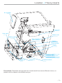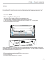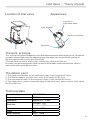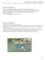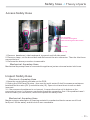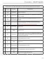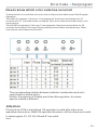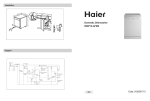
1
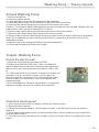
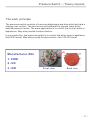
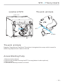
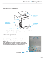
Technical Service Manual
Dishwasher
Contents
Specification
Function Description
2
3-4
Water circuit
3-4
Theory of parts
5-23
Location
5
PCB
6-7
Inlet valve
8-10
Drain pump
11-12
Heater
13-14
Washing pump
15-16
Pressure switch
17
NTC
18-19
Flowmeter
20-21
Safety Hose
22-23
Test program
24-28
Procedure
25
Error code
26-28
Inspection
Troubleshooting
29-32
33-37
SAFETY NOTICE
This documentation is only intended for qualified technicians
who are aware of the respective safety regulations.
- 1-
Specifications
Models:WQP12-B9251B WQP8-B9252B
Electrical supply
220-240V, 50Hz
Supply water pressure
0.04MPa-1.0MPa
Supply water temperature below 60℃
For the basic operation instructions, please refer to the
instruction manual attached with each unit.
- 2-
inlet valve
inlet hose
air breaker
washing pump
regeneration valve
softener
lower spray arm
tube
upper spray arm
top spray
Water circuit scheme
drain pumb
over flow switch
pressure switch
drain hose
Drain water route
Cycle water route
Regeneration water route
Inlet water route
Water Circuit -> Function Description
- 3-
Water Circuit -> Function Description
Process of water inlet (indicated by magenta route)
In this process, regeneration water route is cut off, main water route is open. The water in the main water
route is softened when pass through the softener, and then enter in the tub. During this phase, some of inlet
water will be stored in the air breaker to be regenerating water.
Process of cycle washing (indicated by blue route)
Cycle washing action is driven by washing pump motor. Water can obtain the power during it passing through
the working washing pump, then be pumped into spray arm, pass from spray arm nozzles, over the dishes,
into sump ,where connect to washing pump, and to get in the next water cycle.
Process of regeneration (indicated by green route)
Regeneration valve is open, the regenerating water dissolve salt in the salt chamber of softener, and then
enter in the resin tank to reactivate the resin.
- 4-
Location -> Theory of parts
Air breaker
Dispenser
Inlet valve
Water inlet
Washing pump
Over Heat Proof
Micro-switch
Heater
Filter system
Sump
Pressure switch (140/120)
Pressure switch (83/63)
(only for models whose water filling
be controlled by pressure switch)
Capacity
Softener
Overflow switch
Please Note: Exploded view and part list of each model have some different visions, so
please refer to newest vision Midea sent you.
- 5-
PCB -> Theory of parts
PCB
Printed Circuit Board is the control center of dishwasher, which receive and process signal
from components, send order to components and deal with the feedback information, etc.
Access PCB
Removing the control panel
The control panel can be removed from dishwasher door.
1. Remove the six screws securing the control panel to the door.
2. The control panel will drop down and be free of the door. But, the wiring will
still connected to the control panel.
on
Off
1
2
08
S
Note: For the majority of models, the PCB is located behind the control panel. The minority
of models locate the PCB on the side of strengthening muscle. You can judge the location by
the newest exploded view Midea sent you.
3. Disconnect the connector form PCB.
4. Remove the screws securing the PCB to control panel.
5. Remove the PCB.
6. Reverse the above procedure to install.
- 6-
PCB -> Theory of parts
Map of PCB
Note: This map is applies to 9378A model.
Description
Mark
HEAT
ACL
ACN
IS
EV1-L
RE
ML
PS
D/ED
EV1
EV2
EV3
ISS
ISB
IAQS
FM
FAN
PO
Function
Output for Heating Element
Input of live wire
Input of bull line
Input of Door Switch
Firewire input of inlet valve
Thermister
Washing Pump
Drain Pump
Dispenser
Inlet valve
Softener
Halfload Valve
Salt detect
Rinse detect
Overflow detect
Flowmeter
Fan
Pressure Switch(83/63)
There is small pole’s location difference
between different models.
But the marks on PCB have the same meaning
described on the left side .
- 7-
Inlet Valve -> Theory of parts
Location of inlet valve
Appearance
connect to
inlet water hose
to air breaker
electric coil inside
terminals
The work principle
The inlet valve is electromagnetic valve that decide whether water enter or not. Valves are
normally closed. Each time the appliance requires water, the controller will convey an
electric signal to the coils to open the valves.
The inlet valve consist of electric coil, valve body, valve pole, filter etc.
In a word, the electromagnetic valve can act to allow water enter into machine, when it
receive the order given by controller.
The defeat point
1. The valve coil is broken, so the valve can’t open. It will cause the E1 error.
2. The filter is jammed, so water can’t enter. It will cause the E1 error.
3. The connector is loose, so the valve can’t open. It will cause the E1 error.
4. The valve pole is rusted or locked by dreg, so the valve can’t open or close. It will cause
the E1 or E4 error.
Technical data
Nominal voltage
Frequency
Resistance
Work duty
Flux
Power
Work Pressure
220-240VAC
50/60Hz
Approx:3.4-4.3kΩ
100%ED T25
3min/5min T60
4L/min 15%
6W
0.04-1MPa
- 8-
Inlet Valve -> Theory of parts
Access inlet valve
1. Disconnect power.
2. Remove the water inlet hose. (Note : Be careful of remain water drop.)
3. Remove the baseboard, left baseboard, top panel, left side panel and middle rear
crosspiece.
3. Top panel
4. Left side panel
5. Middle rear
crosspiece
4. Disconnect the 2 terminal lugs
from the inlet valve.
5. Push the valve from the lower
rear crosspiece to take it off.
6. Remove the clamp and
disconnect the inlet hose (to air
breaker) from the water valve.
7. Reverse the above procedure
to install.
1. Baseboard
2. Left baseboard
Inlet valve
Attention: Build in models have no Baseboard and
left and right baseboard, but adjustable baseboard.
Inspect inlet valve
Check electric part
1.Open the control panel and take out the PCB;
2.Unplug the CON3 and P4 wires , then use the multimeter Ω shelf to measure resistance between the blue
wire (EV1) and white wire (IS), the normal resistance is
about 3.4K Ω to 4.3K Ω .
3. I f the measured resistance is not correct, it means the
valve coil is broken or the connector is loose. In this
case, we should check the connection first. If the
problem hasn’t been solved by re-connection, we should
replace the valve..
4.If the resistance is OK, we need to inspect the valve
body.
unplug
IS
EV1
- 9-
Inlet Valve -> Theory of parts
Check machine part
1. If the electric part is OK, we need to check the machine part.
2. Remove the baseboard, left baseboard, top panel, left side panel and middle rear
crosspiece.
3. Check the valve filter. if the valve filter is blocked, we need clear the residues.
4. If the valve filter is clear and the valve can’t inlet water, check whether valve can act or
not. If it isn’t , we need replace the valve.
5. If the water is continue entering, we need replace the valve.
- 10 -
Drain Pump -> Theory of parts
Location of Drain Pump
The work principle
B ottom View
Drain pump integrated into sump
connect to washing pump
terminals
to drain hose
motor
The work principle
Drain pump consists of electrical motor, impeller, inlet and outlet.
Drain pump is a kind of pump driven by permanent magnet synchronous motor. The rotor is
made with permanent magnet material, the running inertia of rotor is very small, the stator
consist of silicon steel stack and coil. When the drain pump is on power, the rotor will be
very easy to start.
The defeat point
1. The motor coil is broken, so the drain pump can’t work. It will cause the E2 , E4 or E1 error
.
2. The magnetism of motor rotor is weak, so drain pump cannot work. It will cause the E2, E4
or E1 error .
3. The connector is loose, so the drain pump can’t work. It will cause the E2, E4 or E1 error .
4. The rotor is locked by residues, so the drain can’t work . It will cause the E2, E4 or E1
error .
5.The drain pump assembly rack is loose, it will cause noise.
6.The non-return valve is bad, the remain water is too much.
Explanatory notes: failure of drain pump may cause E1, becaus
Technical data
Nominal voltage
Frequency
Resistance
Delivery height
Delivery performance
220-240VAC
50Hz
150-220Ω
1M
≥17l/min(230VAC)
- 11 -
Drain Pump -> Theory of parts
Access drain pump
1. Drain off the water in the dishwasher, and
disconnect the power supply。
(Note : Make sure to remove remained water in
the dishwasher. If not, wet the floor.)
2. Remove four screws on bottom, and then
remove bottom board.
3. Label and disconnect the two terminal lugs
from the drain pump.
4. Remove screws securing the drain pump to
sump, then remove drain pump.
5. Reverse the above procedure to install.
Inspect drain pump
Check the electric part
1.Open the control panel and take out the PCB;
2.Unplug the CON4 and P4 wires, then use the multimeter Ω shelf to measure the red wire (PS) and white wire
(IS), the normal resistance is about 150 Ω to 220 Ω .
3. If the measured resistance is not correct, it means the
pump coil is broken or connector is loose. In this case, we
should check the connection first. If the problem hasn’t
been solved by re-connection, we should replace the
drain pump.
4.If the resistance is OK, but it also can’t work, maybe the
magnetism is too weak, so we need to replace the drain
pump.
PS
IS
Check the machine part
1. If the electric part is OK, we need to check the machine part.
2. Remove bottom board.
3. If the non-return valve is wrongly assembled, the tub will remain much water. We need to
re-assemble the non-return valve.
4. If the drain pump is working, but no water drain out or just a little. We should check the
drain hose or drain body.
- 12 -
Heater -> Theory of parts
Location of Heater
The work principle
B ottom View
pressure switch
Technical data
Nominal voltage
Rating power
Resistance
Thermastat1
Thermastat2
230VAC
1800W
29.265 1.463Ω
98℃
229 ℃
The defeat point
1. The heater coil is broken, so the heater cannot work. It will cause the E3 error.
2. The thermostat is active, so the heater cannot work. It will cause the E3 error.
3. The connector is loose, so the heater cannot work. It will cause the E3 error.
- 13 -
Heater -> Theory of parts
B ottom View
Clamps
Ground terminal
Terminals
(measure heater resistance)
Access heater
1. Drain off the water in the dishwasher, and disconnect the power supply.
(Note : Make sure to remove remained water in the dishwasher. If not, wet the floor)
2. Remove bottom board.
3. Label and disconnect the terminals to and ground wire.
4. Remove the 2 clamps from the Heating element.
Caution: The clamp is easily damaged during removal and can’t be reused. Replace the old
clamp with a new universal clamp .
5. Reverse the above procedure to install.
Inspect heater
1. Remove bottom board.
2. Use the multi-meter Ω shelf to measure resistance
between the two terminals shown in right picture, the
resistance is about 29 Ω to 31 Ω .
3. If the measured resistance is not correct, it means the
heater coil or the thermostat is broken, we should replace
the heating element or the thermostat.
terminals
- 14 -
Washing Pump -> Theory of parts
Location of Washing Pump
The work principle
B ottom View
BLUE
BLUE
M
RED
A
150℃
BLACK
M-main coil
A-assistant coil
Washing pump is a kind of asynchronism
motor with capacitor. The stator consist of
silicon steel stack and two coils, main coil and
assistant coil .
The defeat point
1. The motor coil is broken, so the wash pump can’t work. It will cause E3 error.
2. The motor rotor capacitor is weaken, so washing pump can’t start. In this case, it will send
out the electromagnetism noise. If it is continue electrifying motor, the thermal protector will
work. It will cause E3 error.
3. The connector is loose, the wash pump can’t work. It will cause E3 error.
4. The rotor is locked by residues, so the wash pump can’t work . It will cause the E3 error.
5.The drain pump assembly bracket is loose, it will cause noise.
6.If the machine hasn’t been used for long time, there is a possibility the wash pump can’t
starting.
Technical data
Models
YXW65-2B
Items
Nominal voltage 220-240VAC
Frequency
50Hz
Main coil: 84.8 7%Ω
Resistance
Assistant coil:78.6 7%Ω
Delivery height 0.8m
Delivery
≥50l/min(230VAC)
performance
Lock rotor
≤1.50A
current
Operating
0.65A 10%
current
Capacitor
5μF
YXW50-2
220-240VAC
50Hz
Main coil:93.10 7%Ω
Assistant:95.99 7%Ω
1m(230VAC)
≥50l/min(230VAC)
1.0 10%(230VAC)
0.47 10%(230VAC)
3μF
- 15 -
Washing Pump -> Theory of parts
Access Washing Pump
1. Disconnect power.
2. Remove bottom board.
3. Label and disconnect the 2 terminals to the capacitor.
4. Label and disconnect the 2 terminals to the motor wire connector.
5. Remove the clamp fastening the interconnect hose to the sump.
Caution: The clamp is easily damaged during removal and can’t be reused. Replace the old
clamp with a new universal clamp (Dia-31.0mm)
6. Remove the clamp fastening interconnect hose to the lower nozzle .
7. Remove the clamp fastening interconnect hose to heater.
8. Remove the screw and disconnect the ground wire from the wash pump motor assembly.
Note: Do not attempt to remove the bolt and locknut connecting the motor mount to the
dishwasher frame.
9. Remove the motor pump assembly from the dishwasher.
10. Reverse the above procedure to install.
Inspect Washing Pump
Check the electric part
1.Open the control panel and take out PCB;
2.Unplug the CON4 and P4 wires, then use the multimeter Ω shelf to test resistance between two white wire
(ML and IS), the normal resistance is about 78 Ω to 100
Ω.
3. I f the resistance is not correct, it means the pump coil
is broken or the connector is loose, In this case, we
should check the connection first. If the problem hasn’t
been solved by re-connection, we would replace the
washing pump.
4.If the resistance is OK but it cannot work, it maybe the
capacitor weakly, we need to replace the capacitor.
ML
IS
Check the machine part
1. If the electric part is OK, we need to check the machine part.
2. Remove bottom board.
3. Check the pump assembly, if the bracket is loose, it will bring the noise, we need to
tighten it.
4. If the wash pump cannot start and the machine hasn’t been used too long, maybe the
seal element is bond.
5. If the drain pump is working, but no water out or just a little. We should check the vane
wheel.
- 16 -
Pressure Switch -> Theory of parts
The work principle
The pressure switch consists of a moving diaphragm and disc which activate a
change over contact. The contact can be calibrated to trip and reset at the
desired pressure levels, The main application is to control the level of water in
appliances. May also provide flood protection.
In our production, the pressure switch is to control the water level in appliance,
like 83/63 serial. May also provide flood protection, like 140/120 serial.
Manufacturer : Elbi
2
1
3
1- COM
2 - NC
3 - NO
Front view
Back view
- 17 -
NTC -> Theory of parts
Location of NTC
The work principle
B ottom View
NTC
screws
The work principle
Negative Temperature Coefficient Thermistor is integrated into sump, which is used for
measuring temperature of water in the tub.
Access Washing Pump
1. Remove bottom board.
2. Remove two screws securing the NTC to sump(shown in above picture).
3. Take out NTC.
4. Reverse the above procedure to install.
- 18 -
NTC -> Theory of parts
Inspect NTC
1.Open the control panel and take out PCB;
2.Unplug the RE connector(shown in below picture), then use the multi-meter Ω shelf to test
resistance between two blue wire , the normal resistance is shown in below table.
3. I f the resistance is not correct, it means NTC circuit has a problem. In this case, we
should check the connection first. If the problem hasn’t been solved by re-connection, we
would replace the NTC.
unplug
NTC resistance table
NTC
15℃
20℃
25℃
30℃
40℃
50℃
60℃
70℃
80℃
85℃
17.48KΩ
12.12KΩ
10KΩ
8.299KΩ
5.807KΩ
4.144KΩ
3.011KΩ
2.224KΩ
1.667KΩ
1.451KΩ
- 19 -
Flowmeter -> Theory of parts
Location of Flowmeter
Top Panel
Side panel
Baseboard
Left Baseboard
Attention: Build in models have no Baseboard and left and
right baseboard, but adjustable baseboard.
The work principle
Flowmeter is integrated into Air Breaker. Function of
Flowmwter is measure how much water has entered in
appliance. it consists of impeller, tongue tube and
terminal, etc.
When water pass through the flowmeter, moving water
can rotate magnetic impeller, the tongue tube can sense
the impeller’s magnetic and send electronic pulses.
Flowmeter
- 20 -
Flowmeter -> Theory of parts
Access Flowmeter
1. Remove the baseboard, life baseboard, top panel and life side panel.
2. Remove the plastic nut inside tub, which secures the air breaker to tub.(Because
flowmeter is integrated into air breaker, replace air breaker if flowmeter has failure. )
3. Disconnect the wire and remove clamp fastening hose to air breaker.
4. Take out air breaker.
5. Reverse the above procedure to install.
Inspect Flowmeter
1.Open the control panel and take out PCB;
2.Unplug the CON27 wire(shown in below picture), then use the multi-meter Diode shelf to
test whether electrical pulse is sent out from two black wires while water is passing through
flowmeter, or not.
3. If there is continual electrical pulse, the multi-meter will send out sound “de” continually.
4.if there is no electrical pulse, the multi-meter will not send sound. In this case, it means
something wrong with flowmeter circuit. We should check the connection first. If the
problem hasn’t been solved by re-connection, we should replace the air breaker..
FM
- 21 -
Safety hose -> Theory of parts
Location of Safety Hose
Electronic Aquastop Hose
Note: The assembly mode of
mechanical Aquastop hose is the same
as that of universal.
The work principle
Mechanical Aquastop Hose
Electronic Aquastop Hose
There are two types of Safety Hose, mechanical Aquastop hose and electronic Aquastop
hose, which have different principles and assembly modes.
Mechanical Aquastop safety hose has two layers. If water leak and fill the air space
between two layers, the foaming material will expand and lock the hose. In this situation,
the machine might set off E1 alarm.
Electronic Aquastop safety hose also has two layers. But the difference from
mechanical is that if the water leak and flow on the bottom tray, the flooding pressure switch
on the tray will act, the electromagnetic valve on the hose will cut off the water road and the
machine will set off E4 alarm.
- 22 -
Safety hose -> Theory of parts
Access Safety Hose
clamp
wire co nnecter
( no nee d to di stinguish
positive and ne gative elec trode)
bound be lt
clamp r ing
1. Remove baseboard, side baseboard, top panel and left side panel.
2. Remove clamp, cut the bound belt and disconnect the wire connector. Then the Inlet hose
cane pulled out.
3. Reverse the above procedure to assemble.
Mechanical Aquastop Hose
Mechanical Aquastop hose is connected to appliance just as universal water inlet hose.
Inspect Safety Hose
Electronic Aquastop Hose
1.Open the control panel and take out the PCB;
2.Unplug the CON3 and P4 wires , then use the multi-meter Ω shelf to measure resistance
between the blue wire (EV1) and white wire (IS). Open circuit and short circuit are both
incorrect.
3. I f the measured resistance is not correct, it means the valve coil is broken or the
connector is loose. In this case, we should check the connection first. If the problem hasn’t
been solved by re-connection, we should replace the safety hose.
Mechanical Aquastop Hose
Maybe moisture absorption of foaming material in mechanical device cause a self-lock
fault(can’t fill the water) and this lock is non-resettable.
- 23 -
Test Program
Test Program
In order to check the operation of components of appliance and find out the malfunction, we
designed this program for technician.
How to activate Test Program
Test Program Operation
B9251B B9252B
How to activate With door opened,
Test Program
Start Test
Program
Jump into next
step
Program + Power
Close the door
Program
E1
E1
E2
/
E3
E3
E4
E4
E6
E6
E7
E7
To activate test program, with the door opened and machine off, hold down the
Program button and press the POWER button until the machine enter into Test
Program. The appliance will pause and stand by(as step 00). Then close the
door to start the Test Program.
During test program running , you can press Program button to jump into
next step ( except inlet valve step ).
Note: The way to activate test program is slightly different between different models.
- 24 -
Procedure -> Test Program
Procedure of Test Program (for models controlling water filling by flowmeter)
No.
Dis play on
t he s c reen
Description
Process
0
8:88
Initialization
Power on, stand by
1
0A
Inlet Valve
Open inlet valve and feed with 3.6L water(45cm models feed
with 3.0L water).
2
09
3
Washing Pump Dispenser will act once and washing pump will run for 60s in
and Dispenser this step.
Run washing pump and heating element until the water
08/TemperHeating Element temperature reaches 57℃. Then the machine will pause.
ature value
Press Program button to jump into the next step.
4
07
Drain Pump
Drain for 30s.
5
06
Pause
Pause for 10s.
6
05
7
04
8
03
9
02
10
01
11
F*
Inlet Valve
Open inlet valve and feed with 3.6L water(45cm models feed
with 3.0L water). If model is equipped with fan, the fan would
be working during this step.
Washing Pump Run washing pump for 2 mins.
Pause
Pause for 5s.
Washing pump Run washing pump for 1 mins.
Drain Pump and
Regeneration Open regeneration valve and drain for 30s.
Valve
finish
Buzz one sound, stop, and stand by.
- 25 -
Error Code -> Test program
How to know which error code has occurred
To know which error code has occurred, refer to the previous table named Test Program
Operation.
Take 9348 for example, If the error 1 has happened, the buzzer would alarm for 30
seconds and “E1” would be shown on display. Other error alarms would be shown in the
same manner.
Take 9239D for example, if the error 7 has happened, the buzzer would alarm for 30
seconds and the Main, Rinse and Drying indicators would flash simultaneously. Other
error alarms can be deduced from this.
The corresponding relation between indicator combination and error
code shown in above figure.
Notice: the majority of models are follow this regulation, but some
special models is different.
Attention
Priority level of E4 is the highest. E4 operation is valid after other error
operations have done. When E4 operation has done, all the others are invalid.
In test program, E1, E3, E4, E6 and E7 are valid.
Note:
- 26 -
Error Code -> Test program
How does the appliance react when error code occurred
E1 Water filling exceed pre-set time
For the models controlling water filling by flow meter.
If the inlet valve has been opened for 4 minutes but the water quantity hasn’t reached the
desired value(measure by pluses), E1 would occur.
When E1 occurs, the drain pump will run until flowmeter keep motionless for 2 minutes
and all the other components will be stopped immediately. At the same time, the buzzer
will alarm for 30 seconds and error 1 will be shown.
For the models controlling water filling by pressure switch.
If the inlet valve has been opened for 4 minutes but the pressure switch hasn’t act, E1
would occur.
When E1 occurs, the appliance will active drain pump and stop all the other components
immediately. At the same time, the buzzer will alarm for 30 seconds and error 1 will be
shown. Then, drain pump will run till the pressure switch reset and continue draining for
60 seconds.
E3 Heating exceed pre-set time
If the heating element has been working for 60 minutes but the water temperature
detected by NTC hasn’t reached desired value. E3 would occur.
When E3 occurs, the drain pump will run until flowmeter keep motionless for 2 minutes ( if
the model with the pressure switch (83/63),drain pump would run till the pressure switch reset and continue
draining for 60 seconds. ) and all the other components will be stopped immediately. At the
same time, the buzzer will alarm for 30 seconds and the error 3 will be shown.
E4 Overflow
At any time, if overflow micro-switch act and keep for longer than 2 seconds, the E4 would
occur. When E4 occurs, the drain pump will run until flowmeter keep motionless for 2
minutes ( if the model with the pressure switch (83/63),drain pump would run till the pressure switch reset
and continue draining for 60 seconds. ) and all the other components will be stopped immediately.
At the same time, the buzzer will alarm for 30 seconds and error 4 will be shown.
Note: Priority level of E4 is the highest. E4 operation is valid after other error operations
have done. When E4 operation has done, all the others are invalid.
- 27 -
Error Code -> Test program
E6 Open-circuit failure of thermistor
In test program, once open-circuit failure of thermistor is detected by controller, the E6
would occur. When E6 occurs, the drain pump will run until flowmeter keep motionless for 2
minutes ( if the model with the pressure switch (83/63),drain pump would run till the pressure switch reset
and continue draining for 60 seconds. ) and all the other components will be stopped immediately.
At the same time, the buzzer will alarm for 30 seconds and error 6 will be shown.
E7 Short-circuit failure of thermistor
In test program, once short-circuit failure of thermistor is detected by controller, the E7
would occur. When E7 occurs, the drain pump will run until flowmeter keep motionless for 2
minutes ( if the model with the pressure switch (83/63),drain pump would run till the pressure switch reset
and continue draining for 60 seconds. ) and all the other components will be stopped immediately.
At the same time, the buzzer will alarm for 30 seconds and error 7 will be shown.
- 28 -
E1 tree -> Inspection
E1 code
Longer inlet time
Is there any
water in the Tub?
No water
Make a check of inlet
hose of AQUASTOP,
(only for the dishwasher
with AQUASTOP device)
Failure
Replace it to solve
the problem
Little water
Make a check of Tap
Not open Open it to solve the
problem
Opened
Make a check of Inlet
Hose
Failure
Inlet Hose is blocked or
kinked
Failure
solve the problem
OK
Check whether the Inlet
Valve circuit is correct or
not. (mentioned in section
4)
Not
OK
Reconnect the wire of
Inlet Valve circuit and
check again
solve the problem
Correct
Still wrong
Model with Flowmwter
Model with Pressure
Switch(83/63)
Check whether the
Pressure Switch(83/63)
circuit is correct or not.
Not
Reconnect the wire of
Pressure Switch circuit
and check again
OK
solve the problem
Still wrong
Check whether the
Flowmeter circuit is correct
or not. (mentioned in
section 4)
Not
Reconnect the wire of
Flowmeter circuit and
check again
Lower
Give advice to
consumer
OK
Make a check of
Drain Hose
Wrong
Hang correctly to
solve the problem
Replace the
Pressure switch to
solve problem
OK
Still wrong
Make a check of the
Hydraulic pressure.
(0.04-1.0MPa is ok)
Replace the Inlet
Valve to solve
problem
solve the problem
Replace the
Flowmeter to solve
problem
If the problem has not been solved through all
the inspection mentioned above, maybe the
PCB has a malfunction. So, replace PCB and
test again.
- 29 -
E3 tree -> Inspection
E3
Longer heating time
Check water
temperature in the tub
Low
Make a check of over heat
proof heating Micro-switch.
Failure
Replace Switch to
solve the problem
OK
High
Jammed
Check whether the filter is
jammed severely or not
Clear or replace filter
to solve the problem
OK
Make a check of Heater.
(mentioned in section 4)
Failure
Reconnect the wire of
Heater circuit and check
again
OK
solve the problem
Still wrong
OK
Check whether the
Washing Pump circuit is
correct or not. (mentioned
in section 4)
Not
Reconnect the wire of
Washing Pump circuit
and check again
OK
Still wrong
Check whether the
NTC circuit is correct
or not.(mentioned in
section 4)
Not
Reconnect the wire of
NTC circuit and check
again
Replace the Inlet
Valve to solve
problem
solve the problem
Replace the
Washing Pump to
solve problem
OK
solve the problem
Still wrong
Replace the NTC to
solve problem
- 30 -
E4 tree -> Inspection
E4
Overflow
Is there any water on
the bottom board?
No water
Make a check of
Flooding Switch
circuit(normally closed)
Failure
Reconnect the wire of
Flooding Switch circuit
and check again
OK
solve the problem
Still wrong
Some
water
Make sure consumer use
the proper detergent and
rinse
Check whether Flooding
Switch is blocked or not
Blocked
Repair or Replace it
to solve problem
Improper
Give advice
OK
Make a check of
Drain Hose
Model with Pressure
Switch(83/63)
Failure
Drain Hose is kinked
or blocked
Failure
Not
Reconnect the wire of
Flowmeter circuit and
check again
OK
Correct
Solve the problem
OK
Model with
Flowmeter
Check whether the
Flowmeter circuit is correct
or not. (mentioned in
section 4)
solve the problem
Still wrong
Check whether the
Pressure Switch(83/63)
circuit is correct or not.
Correct
Not
Reconnect the wire of
Pressure Switch circuit
and check again
Replace the
Flowmeter to solve
problem
OK
Still wrong
solve the problem
Replace the
Pressure Switch to
solve problem
Maybe there is a real
leakage
Do as follows
Remove two side panels
Remove the water from the bottom board and make sure there is no water at the bottom board.
Restart the dishwasher with a strong or standard wash program as a leakage could easily repeat at a higher temperature and after a long period
of running time.
Observe the bottom tray every twenty minutes.
If any water appears, you will found out which areas, such as motor, drain pump, sump, softener, and hoses between them, and also clips at the
end of each hose, besides the weld seam at the bottom of the tub.
If hours passed, but no water comes out, you should stop the dishwasher with sufficient water in the inner tub, and observe it again after leaving
it alone for one to two hours.
- 31 -
E6&E7 tree -> Inspection
E6
Open-circuit failure of
thermistor
Check whether the NTC
circuit is correct or not.
(mentioned in section 4)
Not
Reconnect the wire of
Flowmeter circuit and
check again
OK
solve the problem
Still wrong
Replace the NTC to
solve problem
E7
Short-circuit failure of
thermistor
Check whether the NTC
circuit is correct or not.
(mentioned in section 4)
Not
Reconnect the wire of
Flowmeter circuit and
check again
Still wrong
OK
solve the problem
Replace the NTC to
solve problem
If the problem has not been solved through all the inspection mentioned above, maybe the
PCB has a malfunction. So, replace PCB and test again.
Caution:
Because the real situation is unpredictable, inspection trees mentioned in this manual are
for reference only.
- 32 -
Troubleshooting
- 33 -
Troubleshooting
- 34 -
Troubleshooting
- 35 -
Troubleshooting
- 36 -
Troubleshooting
- 37 -