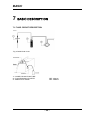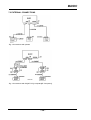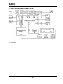
1
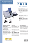
BASIC
Service manual
Ref. 0NVBAT
Manual version: 1.18
SYSTEME QUALITE CERTIFIE
SECOMAM, a NOVA ANANLYTICS Company,
91, Avenue des Pins d’Alep
30319 ALES FRANCE
Tel: +33 4 66 54 35 60
Fax: +33 4 66 54 35 69
E-mail: [email protected]
URL: www.secomam.fr
BASIC
SUMMARY
1 REMARKS ......................................................................................................................................................... 5
2 WARRANTY...................................................................................................................................................... 7
3 INFORMATION ................................................................................................................................................ 9
4 PRECAUTIONS OF USE ............................................................................................................................... 11
5 HOW TO USE THIS GUIDE ......................................................................................................................... 13
6 TROUBLESHOOTING................................................................................................................................... 15
6.1 PRECAUTIONS BEFORE INVESTIGATIONS ........................................................................................ 15
6.2 TROUBLES, EXPLANATIONS AND SOLUTIONS ................................................................................ 17
7 BASIC DESCRIPTION................................................................................................................................... 25
7.1 FLUID CIRCUIT DESCRIPTION .............................................................................................................. 25
7.2 EXTERNAL CONNECTIONS ................................................................................................................... 26
7.3 ELECTRIC INTERNAL CONNECTIONS................................................................................................. 27
7.4 SPARE PARTS DESCRIPTION................................................................................................................. 28
8 SPARE PARTS AND EPROM ....................................................................................................................... 31
8.1 SPARE PARTS ........................................................................................................................................... 31
8.2 EPROM EVOLUTION................................................................................................................................ 32
9 REPAIRING..................................................................................................................................................... 33
9.1 LIST OF TOOLS AND CONTROL STANDARDS.................................................................................... 33
9.2 BASIC OPENING ....................................................................................................................................... 34
9.3 PUMP PERISTALTIC HEAD REPLACING ............................................................................................. 37
9.4 BATTERY REPLACING ........................................................................................................................... 38
9.5 LAMP REPLACING ................................................................................................................................... 39
9.5.1 WARNING ............................................................................................................................................ 39
9.5.2 CHECKING THE LAMP ...................................................................................................................... 39
9.5.3 REPLACING THE HALOGEN LAMP ................................................................................................. 39
9.6 MICROPROCESSOR BOARD AND POWER SUPPLY BOARD REPLACING ..................................... 41
9.6.1 MICROPROCESSOR BOARD REPLACING ....................................................................................... 41
9.6.2 POWER SUPPLY REPLACING ........................................................................................................... 42
9.7 EPROM AND MICROPROCESSOR BOARD BATTERY REPLACING................................................. 45
9.7.1 REPLACING THE EPROM.................................................................................................................. 45
9.7.2 BATTERY OF MICROPROCESSOR BOARD REPLACING ............................................................... 46
9.8 FAN REPLACING ...................................................................................................................................... 47
9.9 PERISTALTIC PUMP MOTOR REPLACING .......................................................................................... 48
9.10 TEMPERATURE SENSOR AND PELTIER EFFECT REPLACING...................................................... 50
9.10.1 TEMPERATURE SENSOR REPLACING........................................................................................... 51
9.10.2 PELTIER EFFECT REPLACING....................................................................................................... 52
9.10.3 FILTERS REPLACING....................................................................................................................... 53
9.10.3.1 Previous BASIC analyzer version..................................................................................................................54
9.10.3.2 New BASIC analyzer version ........................................................................................................................56
9.11 FRONT PANEL SPARE PARTS REPLACING ....................................................................................... 57
9.11.1 VIAL POSITION OPTICAL DETECTOR REPLACING .................................................................... 57
9.11.2 DISPLAY REPLACING ...................................................................................................................... 58
9.11.3 KEYBOARD REPLACING ................................................................................................................. 58
9.11.4 INTERFACE BOARD REPLACING................................................................................................... 58
-3-
BASIC
10 ADJUSTMENTS AND CONTROLS ...........................................................................................................59
10.1 HOW TO ENTER IN TEST PROGRAM ..................................................................................................59
10.2 OPTICAL ALIGNMENT ..........................................................................................................................61
10.3 WAVELENGTH CONTROL AND ADJUSTMENT................................................................................63
10.4 ABSORBANCE CHECKING ...................................................................................................................65
10.5 BACKGROUND NOISE CHECKING......................................................................................................66
10.6 STRAYLIGHT CHECKING .....................................................................................................................67
10.7 TEMPERATURE CHECKING .................................................................................................................68
10.7.1 TEMPERATURE CYCLE EXPLANATION ........................................................................................68
10.7.2 TEMPERATURE CHECKING............................................................................................................69
10.8 ASPIRATION ADJUSTMENT.................................................................................................................70
10.9 CONTAMINATION CONTROL ..............................................................................................................72
10.10 FLOW-THROUGH CUVETTE HEIGHT ADJUSTMENT ....................................................................73
11 DRAWING......................................................................................................................................................75
12 RS 232C OUTPUT .........................................................................................................................................89
12.1 CONNECTOR ................................................................................................................................................89
12.2 PRINTER...................................................................................................................................................89
12.3 DATA SIZE ...............................................................................................................................................89
12.4 DATA TRANSMISSION RATE ...............................................................................................................89
13 PARALLEL CENTRONICS OUTPUT .......................................................................................................91
13.1 CONNECTOR ...........................................................................................................................................91
13.2 PRINTERS.................................................................................................................................................91
14 GLOSSARY....................................................................................................................................................93
-4-
BASIC
1 REMARKS
The Automatic aspiration system kit is manufactured by SECOMAM.
The information contained in this document may be the object of patents or patent applications by
SECOMAM. The possession of this document does not confer any license to such patents.
The following names are SECOMAM’s registered trademarks throughout the world.
SECOMAM
BASIC
This manual is updated periodically. The updates are included in the new editions.
All information supplied in this edition of the manual may be amended before the products described
herein are available.
All reproduction rights reserved.
Reference
0NVBAT
Date of last
modification
Version
Date of document.
Writer
07/12/05
1.18
01/10/00
WJ
-5-
Controller
Approving
BASIC
2 WARRANTY
The new equipment and material sold by SECOMAM is guaranteed against any manufacturing defects
for one year (unless otherwise stated by SECOMAM) with effect:
− From the technical acceptance of the equipment in the factory by the buyer or his designee,
− or failing this :
* For Metropolitan France: from the date on the delivery note.
* For other destinations: from the date of factory shipment certified by air waybill,
consignment note or bill of lading.
The SECOMAM company guarantee applies exclusively to defectiveness arising from a design fault or
from a concealed defect. It is strictly limited to the free dispatching of replacement parts (except for
consumable items) or to the repairing of the equipment in our workshops within a deadline of 10
working days (shipping delay not included).
By express agreement, the following are strictly excluded from our guarantee:
− All damages, notably for staff costs, loss of earnings, business trouble, etc
− Any breakdown due to an incorrect use of the equipment (non adapted mains, fall, attempt at
transformation, etc) or to a lack of maintenance by the user or to poor storage conditions.
− Any breakdown due to the use of parts not supplied by SECOMAM, on SECOMAM equipment
− Any breakdown due to the transporting of the equipment in packaging which is not its original
packaging
− The lamps, the cells and generally any item which appears in the "accessories" section on the
price list.
Our customers are kindly asked to apply for our consent before returning any instrument for repair. No
return of materials may be accepted without the prior written consent of our Sales Management which
will precise the terms of such return.
If the above consent is given, articles shall be returned in their original packaging on a prepaid basis to
the following address:
SECOMAM - 91 avenue des Pins d’Alep – 30100 ALES FRANCE
We reserve the right to reship all instruments received collect failing such consent.
Whatever method and conditions of transport are chosen for the shipment of the equipment to be
repaired under guarantee, in the original packaging, the corresponding costs and the insurance costs
will be payable by the customer.
Any damage connected to the return transport of the equipment falls within the framework of the
guarantee on the express condition that the customer has sent his complaint within forty-eight hours
by registered letter with acknowledgement of receipt to the carrier. A copy of the letter should be sent
to SECOMAM.
For equipment with a guaranty card, this is only applicable if the card delivered with the equipment is
returned to SECOMAM duly completed.
-7-
BASIC
SOFTWARE GUARANTEE
The software is guaranteed by the designer or the distributor of the software under the conditions
specified in the literature accompanying the aforementioned software packages.
Under no circumstances whatsoever will SECOMAM supply any type of guarantee for software
packages.
By express agreement, all damages, notably for staff costs, lost of earnings; business trouble, etc are
strictly excluded from our guarantee.
The customer is informed that the software cannot be guaranteed exempt from defects or bugs.
TRADE SECRET AND PROPERTY RIGHTS
This document is protected by a SECOMAM copyright (c) 2003 and the copying rights are explicitly
reserved. The software supplied with the equipment or referenced contains trade secrets and
confidential information which are SECOMAM's property. It is legally protected by the international
copyright (c) laws.
SECOMAM grants a license to use its software to the user. This may not be disclosed, used or
duplicated with the intention to save it, without SECOMAM's written permission. The beneficiary must
attach a copy of this document to all authorized partial or total reproductions.
-8-
BASIC
3 INFORMATION
The SECOMAM equipment has been designed, manufactured, tested and inspected according to the
ISO 9001 standards.
If the unit is not immediately installed, it should be stored in a dry and clean area. The storage
temperature should be between 10 and 35°C.
SECOMAM equipment is carefully inspected before it is packed. As soon as you receive your
equipment, check the condition of the packaging and if you notice any problems, notify your carrier
within 48 hours. Then consult the packing list and check that everything is in order. Finally, if you
discover that something is missing, or if the goods are damaged immediately notify SECOMAM.
IMPORTANT:
In order to benefit from SECOMAM’s service (application notes, SECOMAM information, technical
assistance, etc.) immediately complete the attached guarantee card and return it to the following
address:
SECOMAM
Service PRODUIT
91 Avenue des Pins d’Alep
30319 ALES Cedex
FRANCE
Tel: +33 4 66 54 35 60
Fax: +33 4 66 54 35 69
E-mail: [email protected]
Service Department: +33 4 66 54 35 63
Technical support: +33 1 39 35 42 12
-9-
BASIC
4 PRECAUTIONS OF USE
¾
Always make sure that the instrument is connected on the good voltage.
(Between 100 – 240V 50-60Hz)
¾ Always disconnect the mains plug before starting any work inside the
instrument.
¾ When dangerous substances for health and environment are used, the
laboratory or site rules, where the instrument is installed must be
followed.
¾
Take all the necessary precautions, during the use the instrument, to
protect the operator from eventual liquids leaks or spills or possible
radiations (protective gloves, anti radiation glasses , protected clothes,
etc)
¾ All operations made inside the instrument, must be done by SECOMAM
or by SECOMAM’s authorized technicians.
- 11 -
BASIC
5 HOW TO USE THIS GUIDE
REMARK :
The object of this servicing manual is to repair and recalibrate SECOMAM’s BASIC
spectrophotometers.
It has been made to help servicing persons to detect the deficient subset order their replacement, to
do the calibration and the test of spectrophotometer.
This servicing manual doesn’t contain any information to repair the mechanical subset and electronics
on their own; it being done exclusively by SECOMAM.
You will find in this servicing manual the following chapter :
- Troubleshooting (See chapter 6 page 15).
- Instrument description (See chapter 7 page 25).
- Spare parts and EPROM{XE "EPROM"} evolution (See chapter 8 page 31).
- Spare parts change and adjustment (See chapter 9 “REPAIRING” page 33).
- Instrument general adjustment and control (See chapter 10 page 59).
- Boards electronical drawings (See chapter 11 page 75)
- Outputs specifications (See chapter Erreur ! Source du renvoi introuvable. page Erreur ! Signet
non défini.).
- 13 -
BASIC
6 TROUBLESHOOTING
6.1 PRECAUTIONS BEFORE INVESTIGATIONS
.Fig. 1 Optical components view
IMPORTANT
80 % of instruments failures are not due to the optical components (grey parts of the above
drawing). So intervene on these parts only if needed.
- 15 -
BASIC
Before any investigations verify:
Room temperature{XE "Temperature"}
15 – 28°C
Room condition
Dry and clean area
Protected from direct light (sun, lamp,…).
Table
Able to support a 12 kg minimum weight.
Voltage
115/230 VAC ± 10 %
Frequency
50-60 Hz
Power
50 W
Electrical plug
Must be fitted with an earth connection in conformity with the standards in force
Mains
Protected against short cuts and abnormal voltage variation (through regulator or
inverter).
Transformer{XE "Transformer"} connection
Verify the connection between the transformer{XE "Transformer"} and the main plug
BASIC connection
Verify the connection between the BASIC and the transformer.{XE "Transformer"}
Fluidic circuit
- Tubes assembly
- Flow-through cuvette{XE "Flow-through cuvette"} setting.
- Pump peristaltic head setting.
- Dead volume{XE "Dead volume"} adjustment.
- Suction volume adjustment.
- Possibility of bubble or piece of material in flow-through cuvette{XE "Flow-through
cuvette"} window{XE "Window"}
Screen
Back-lit adjustment.
Vial detection
Vial detection adjustment.
Printer{XE "Printer"}
Conformity between the printer{XE "Printer"} chosen with:
- printer{XE "Printer"} selected,
- output port used (serial or parallel{XE "Parallel"}),
- connection cable used
Methodology
Conformity between analysis runned and methodology technical notice
- 16 -
BASIC
6.2 TROUBLES, EXPLANATIONS AND SOLUTIONS
TROUBLES
During zero measurement, the unit displays “ Measurement problem. Repeat?”
EXPLANATION
The optical detector{XE "Optical detector"} (diode array) does not receive enough energy{XE "Energy"}
SOLUTION
Verify if
- the halogen lamp{XE "Halogen lamp"} switches on correctly,
- optical sides of flow-through cuvette{XE "Flow-through cuvette"} are clean,
- there is distilled water inside flow-through cell,
- aspiration{XE "Aspiration"} and dead volume{XE "Dead volume"}s are correctly programmed,
- there are no bubbles{XE "Bubbles"} or impurities{XE "Impurities"} inside flow-through cuvette{XE "Flow-through cuvette"} in
the measure chamber,
- the distance between the bottom and the center of the measure window{XE "Window"} of flow-through cuvette{XE "Flowthrough cuvette"} is 8,5 mm,
- the flow-through cuvette{XE "Flow-through cuvette"} is correctly setting inside the cuvette compartment,
- inlet filter{XE "Filter"} is becoming oxydized (due to extreme weather conditions),
Remove flow through cuvette and try again.
§ and Chapter
See paragraph 10.10 FLOW-THROUGH CUVETTE HEIGHT ADJUSTMENT page 73
TROUBLES
Printing problem
- Beeping noise{XE "Beeping noise"} when the BASIC, connected with printer,{XE "Printer"} is switching on.
EXPLANATION
There is no communication between the BASIC and the printer{XE "Printer"}
SOLUTION
Verify if
- the chosen printer{XE "Printer"} (serial or parallel{XE "Parallel"}) is connected to the right output port (serial or parallel),
- the printed is correctly programmed,
- the printer{XE "Printer"} is correctly connected to the mains,
- the printer{XE "Printer"} is connected to the BASIC
- the selected printer{XE "Printer"}, in the software BASIC, is the one used,
- the selected baud{XE "Baud"} rate, in the software BASIC, is the one programmed on the printer{XE "Printer"},
- the used cable between BASIC and printer{XE "Printer"} is the right one (cable is different if it is a serial or parallel{XE
"Parallel"} printer),
Change the power supply board{XE "Power supply board"} (ref: 416662A).
§ and Chapter
See chapter 12 RS 232C OUTPUT page 89
TROUBLES
Cuvette holder{XE "Cuvette holder"} is too hot or to cold
EXPLANATION
Temperature{XE "Temperature"} regulation{XE "Temperature regulation"} of cuvette holder{XE "Cuvette holder"} is not
working correctly. It is due to the temperature sensor{XE "Temperature sensor"} or to the temperature command.{XE
"Temperature command"}
SOLUTION
Verify if
- the temperature{XE "Temperature"} sensor{XE "Temperature sensor"} is at its right place.
Change the temperature{XE "Temperature"} sensor{XE "Temperature sensor"} (ref: 416680).
Change the power supply board{XE "Power supply board"} (ref: 416662A).
§ and Chapter
See § 9.10.1 “TEMPERATURE SENSOR REPLACING” page 51
- 17 -
BASIC
TROUBLES
Working temperature{XE "Temperature"} is never reached.
EXPLANATION
The Peltier effect{XE "Peltier effect"} component is out of order.
The Peltier effect{XE "Peltier effect"} command is out.
SOLUTION
Change Peltier effect{XE "Peltier effect"} component (Ref: 410357P).
Change the power supply board{XE "Power supply board"} (ref: 416662A).
§ and Chapter
See § 9.10.2 “PELTIER EFFECT REPLACING” page 52
TROUBLES
No automatic sample aspiration.{XE "Aspiration"}
EXPLANATION
Vial/cuvette position detector is blinded by external light.
Quality of the vial is not good (plastic quality, vial roundness quality)
Vial/cuvette position detector is out.
Potentiometer{XE "Potentiometer"} which adjust the sensibility of vial/cuvette detector position is not well adjust.
Command of vial/cuvette position detector is out.
SOLUTION
Verify if the user did not program the BASIC functioning “cuvette after cuvette”
Verify with white sheet of paper if you realize the aspiration{XE "Aspiration"}.
Verify the potentiometer{XE "Potentiometer"} which adjust the sensibility of vial/cuvette detector position (Out or bad position).
Try to realize aspiration{XE "Aspiration"} by moving vial/cuvette position.
Verify vial/cuvette plastic quality.
Verify connection between the detector and interface board{XE "Interface board"}.
Verify connection between interface board{XE "Interface board"} and micro-processor board.
Change the microprocessor board{XE "Microprocessor board"} (ref 416662B).
§ and Chapter
See paragraph 9.11.1 VIAL POSITION OPTICAL DETECTOR REPLACING page 57
TROUBLES
Untimely realize aspiration.{XE "Aspiration"}
EXPLANATION
There is a too great light source (sun, spot, white surface…) near the vial/cuvette position detector.
SOLUTION
Protect the vial/cuvette position detector from external light
§ and Chapter
- 18 -
BASIC
TROUBLES
The peristaltic doesn’t work.
EXPLANATION
Peristaltic pump{XE "Peristaltic pump"} head is not correctly set up.
Peristaltic pump{XE "Peristaltic pump"} tubes are not correctly set up.
Peristaltic pump{XE "Peristaltic pump"} motor{XE "Motor"} is not fed.
SOLUTION
Verify:
- the assembly of the peristaltic pump{XE "Peristaltic pump"} head
- the assembly of the peristaltic pump{XE "Peristaltic pump"} tubes.
- connection between pump peristaltic motor{XE "Motor"} and power supply board{XE "Power supply board"}.
Change the power supply board{XE "Power supply board"} (ref: 416662A).
§ and Chapter
See chapter 9.9 “PERISTALTIC PUMP MOTOR REPLACING” page 48
TROUBLES
Nothing on the display and{XE "Display"} the fan{XE "Fan"} does not work.
EXPLANATION
BASIC is not correctly fed.
Power supply board{XE "Power supply board"} is out.
SOLUTION
Verify:
- connection between the mains and the transformer{XE "Transformer"}.
- connection between the transformer{XE "Transformer"} and the BASIC.
- internal connections.
Change the transformer{XE "Transformer"}.
Change the power supply board{XE "Power supply board"} (ref: 416662A).
§ and Chapter
See paragraph 9.6 MICROPROCESSOR BOARD AND POWER SUPPLY BOARD REPLACING page 41
TROUBLES
Nothing on the display,{XE "Display"} but the fan{XE "Fan"} is working correctly.
EXPLANATION
Back lit{XE "Back lit"} is not correctly adjusted.
Connection problem between display{XE "Display"} and boards
The display{XE "Display"} is out.
SOLUTION
Verify:
- the potentiometer{XE "Potentiometer"} which adjust the back lit{XE "Back lit"} (Out or bad position).
- connection between display{XE "Display"} and interface board{XE "Interface board"}.
- connection between display{XE "Display"} and power supply board{XE "Power supply board"}.
- connection between interface board{XE "Interface board"} and microprocessor board{XE "Microprocessor board"}.
Change the microprocessor board{XE "Microprocessor board"} (ref 416662B).
Change the interface board{XE "Interface board"} (ref: 0X6676).
§ and Chapter
See paragraph 9.11.2 DISPLAY REPLACING page 58
- 19 -
BASIC
TROUBLES
Absorbance{XE "Absorbance"} values are too high.
EXPLANATION
Something blocks the beam{XE "beam"}{XE "Beam"} or there is no beam.
SOLUTION
Verify:
- flow-through cuvette{XE "Flow-through cuvette"} position
- if there any bubbles{XE "Bubbles"} or impurities{XE "Impurities"} inside the flow-through cuvette{XE "Flow-through cuvette"}.
- if the aspiration{XE "Aspiration"} volume is correctly adjusted (presence of bubbles{XE "Bubbles"}).
Change the halogen lamp{XE "Halogen lamp"}
§ and Chapter
See chapter 9.5 “LAMP REPLACING” page 39
TROUBLES
BASIC can not zeroing.
EXPLANATION
Something blocks the beam{XE "beam"}{XE "Beam"} or there is no beam.
SOLUTION
Verify:
- flow-through cuvette{XE "Flow-through cuvette"} position
- if there any bubbles{XE "Bubbles"} or impurities{XE "Impurities"} inside the flow-through cuvette{XE "Flow-through cuvette"}.
- if the aspiration{XE "Aspiration"} volume is correctly adjusted (presence of bubbles{XE "Bubbles"}).
Change the halogen lamp.{XE "Halogen lamp"}
§ and Chapter
See chapter 7.1 “FLUID CIRCUIT DESCRIPTION” page 25
TROUBLES
Absorbance{XE "Absorbance"} values are negative
EXPLANATION
Solution used to do the zero has an absorbance{XE "Absorbance"} higher than the sample absorbance.
SOLUTION
Verify:
- absorbance{XE "Absorbance"} of the solution used to do the zero.
- if there any bubbles{XE "Bubbles"} or impurities{XE "Impurities"} inside the flow-through cuvette{XE "Flow-through cuvette"} during
the zero.
- if the aspiration{XE "Aspiration"} volume is correctly adjusted (presence of bubbles){XE "Bubbles"}.
§ and Chapter
See user’s manual
TROUBLES
Instability on the results.
EXPLANATION
Halogen lamp{XE "Halogen lamp"} is ready to dead.
Sample is not stable or very concentrated.
SOLUTION
Change halogen lamp{XE "Halogen lamp"}.
Verify:
- sample quality.
- sample concentration.
- presence of bubbles{XE "Bubbles"} or impurities{XE "Impurities"} inside the sample.
§ and Chapter
See chapter 9.5 “LAMP REPLACING” page 39
- 20 -
BASIC
TROUBLES
Display{XE "Display"} inscriptions are not legible.
Explanation
The BASIC is in stand-by mode.
The basic is fed of by the battery.{XE "Battery"}
SOLUTION
Press a key to go out of stand-by mode.
Verify external BASIC power connections (transformer,{XE "Transformer"} mains).
§ and Chapter
TROUBLES
During mains cut off, BASIC switch off.
Explanation
The battery{XE "Battery"} does not take over from the mains
SOLUTION
Recharge the battery{XE "Battery"}.
Change the battery{XE "Battery"}.
Verify connections between battery{XE "Battery"} and power supply board{XE "Power supply board"}
Change
Verify external BASIC power connections (transformer,{XE "Transformer"} mains).
§ and Chapter
See chapter 9.4 “BATTERY{XE "Battery"} REPLACING” page 38
TROUBLES
Date are not keep in memory.
Explanation
Microprocessor battery{XE "Battery"} is out
SOLUTION
Change the microprocessor battery.{XE "Battery"}
§ and Chapter
See chapter 9.7 “EPROM{XE "EPROM"} AND MICROPROCESSOR BOARD BATTERY REPLACING” page 45
TROUBLES
No repeatability between two measurements using decreasing kinetic
Explanation
Samples are not prepared in same conditions
Problem on BASIC temperature{XE "Temperature"}
SOLUTION
Verify:
- analysis programming (check the reagent technical notice).
- reagent volume.
- sample volume.
- reagent quality (validity date).
- reagent temperature{XE "Temperature"} (room or measure temperature)
- waiting time.
- measuring time.
- BASIC temperature.{XE "Temperature"}
§ and Chapter
See user’s manual.
- 21 -
BASIC
TROUBLES
Contamination{XE "Contamination"} between samples
Explanation
Sample volume is to low.
Aspiration{XE "Aspiration"} or dead volumes{XE "Dead volume"} are not correctly adjusted.
SOLUTION
Verify:
- dead volume{XE "Dead volume"} (about 200 µl).
- aspiration{XE "Aspiration"} volume (minimum 800 µl).
Verify, in the reagent technical notice, if the reagent manufacturer does not advocate a cuvette by cuvette measurement.
§ and Chapter
See § 10.9 “CONTAMINATION CONTROL” page 72 and § 10.8 “ASPIRATION ADJUSTMENT” page 69
TROUBLES
Relay{XE "Relay"} K3 (on power supply board){XE "Power supply board"} is chattering and the lamp goes off during measurement
Explanation
There is a short cut between the radiator{XE "Radiator"} (RA3) of regulator LM323K (U7) and the track under the radiator
The short cut is located close capacitor C25 & C26.
SOLUTION
Isolate the radiator{XE "Radiator"} from the track under.
§ and Chapter
See drawing page 75
TROUBLES
Bridge{XE "Bridge"} rectifier{XE "Rectifier"} CR1 of power supply board{XE "Power supply board"} become very hot and burns
Explanation
When the Peltier effect{XE "Peltier effect"} heats, the current in the transistorQ2 becomes important because it is not limited enough
by the resistor{XE "Resistor"} R29, so the bridge{XE "Bridge"} rectifier{XE "Rectifier"} becomes hot and burns.
SOLUTION
- Add a heat spreader on the bridge{XE "Bridge"} rectifier{XE "Rectifier"} CR1 if there is no.
- Replace the resistor{XE "Resistor"} R29 (0.1 Ohm) by a 0.2 Ohm
§ and Chapter
See drawing page 75
TROUBLES
During the zero, it displays
{XE "Bridge"}{XE "Rectifier"}{XE "Power supply board"}
Explanation
The cell amplifier does not receive energy from halogen lamp during the zero measurement.
SOLUTION
- Change halogen lamp.
§ and Chapter
See chapter 9.5 “LAMP REPLACING” page 39
- 22 -
BASIC
TROUBLES
During the zero, it displays
{XE "Bridge"}{XE "Rectifier"}{XE "Power supply board"}
Explanation
The cell amplifier does not send information to the microprocessor board.
SOLUTION
- Verify connection between cell amplifier board and microprocessor board.
§ and Chapter
See paragraph 7.3 ELECTRIC INTERNAL CONNECTIONS page 27.
- 23 -
BASIC
7 BASIC DESCRIPTION
7.1 FLUID CIRCUIT DESCRIPTION
.Fig. 2 BASIC fluid circuit
1 – GUIDE FOR SUCTION TUBE.
2 – FLOWTHROUGH CUVETTE
3 - PERISTALTIC PUMP.
REF: 0G6716
REF: 0M6679
- 25 -
BASIC
7.2 EXTERNAL CONNECTIONS
.Fig. 3 Connections with printers
.Fig. 4 Connections with PC{XE "PC"} computer{XE "Computer"}
- 26 -
BASIC
7.3 ELECTRIC INTERNAL CONNECTIONS
.Fig. 5 Synoptic
- 27 -
BASIC
7.4 SPARE PARTS DESCRIPTION
.Fig. 6 BASIC front view
1 – KEYBOARD
2 – DISPLAY
3 – SUCTION TUBE
REF: 0W6791
.Fig. 7 BASIC rear view
1
2
3
4
5
6
7
8
9
10
– SUCTION TUBE GUIDE.
– PERISTALTIC PUMP.
REF: 0M6679
– ON/OFF SWITCH.
– 12V POWER SUPPLY CONNECTOR
– RS 232C{ XE "RS 232C" } PORT (serial).
– PARALLEL PORT (centronics{ XE "Centronics" }).
– BATTERY COMPARTMENT.
– FAN.
– BACK LIT ADJUSTMENT.
- SENSIBILITY ADJUSTMENT OF VIAL POSITION DETECTOR.
- 28 -
BASIC
.Fig. 8 Monochromator{XE "Monochromator"} view
1 – CELL AMPLIFIER BOARD
REF: 0X6689.
2 – GRATING SUBSET (grating & lens{ XE "Lens" })
3 – TEMPERATURE SENSOR
REF: 416680
4 – CELL HOLDER
5 – FILTER HOLDER
REF: 406670
6 – HALOGENE LAMP
REF: 80ST0200
.Fig. 9 Main boards view
1 – BATTERY.
2 – FAN.
3 – MICROPROCESSOR BOARD
4 – POWER SUPPLY BOARD
5 – PUMP PERISTALTIC HEAD
6 – PUMP PERISTALTIC MOTOR
REF: 410357V.
REF: 416662B.
REF: 416662A.
REF: 0M6679.
REF: 410357M.
- 29 -
BASIC
.Fig. 10 Front panel rear view
1 – SUCTION TUBE GUIDE.
2 – VIAL POSITION OPTICAL DETECTOR
3 – DISPLAY BOARD
4 – INTERFACE BOARD
5 – SENSIBILITY ADJUSTMENT OF VIAL POSITION DETECTOR
- 30 -
REF: 0X6708.
REF: 416391VB.
REF: 0X6676.
REF: 0M6679.
BASIC
8 SPARE PARTS AND EPROM{XE "EPROM"}
8.1 SPARE PARTS
REFERENCE
0EBAC
0M6679
0M6905
0NVBAT
0NVBAU
0NVBFU
0W6791
0X0357C
0X6676
0X6689
0X6708
0X6798
404611BA
406670
406670
406671
410357M
410357P
410357V
416391VB
416659
416662A
416662B
416680
80ST0200
80VB0363
80VB0380
DESIGNATION
Packing box
Peristaltic pump{XE "Peristaltic pump"}
tube
Transformer{XE
"Transformer"}
with
European plug
English technical manual
English user’s manual
French user’s manual
Keyboard{XE "Keyboard"}
Armed flat cable
Interface board{XE "Interface board"}
Cell amplifier board{XE "Cell amplifier
board"}
Vial/cuvette position detector
Cable for KYOLINE printer{XE "Printer"}
Set
of
programmed
EPROM{XE
"EPROM"}
Filters holder
BG38 filter{XE "Filter"} subset
BG39 filter{XE "Filter"} subset
Motor{XE "Motor"} of peristaltic pump{XE
"Peristaltic pump"}
Peltier effect{XE "Peltier effect"}
Fan{XE "Fan"}
Display{XE "Display"} subset (phase3)
Display{XE "Display"} subset (phase2)
Power supply board{XE "Power supply
board"}
Microprocessor board{XE "Microprocessor
board"}
Temperature{XE
"Temperature"}
sensor{XE "Temperature sensor"}
Halogen lamp{XE "Halogen lamp"}
Tubes kit
Tubes
kit
&
peristaltic pump{XE
"Peristaltic pump"} head
- 31 -
BASIC
8.2 EPROM{ XE "EPROM" } EVOLUTION
EPROM{ XE "EPROM" } VERSION
DATE
V1.8d
20/06/97
V1.11
05/09/97
V1.12
29/09/97
V1.13a & V1.13b
05/01/98
V1.14a & V1.14b
19/01/98
V1.15a
12/05/98
V1.17
29/09/98
V1.17a
29/01/99
V1.17b
15/02/99
V1.17c
17/03/99
V1.17d
19/03/99
V1.17 e
25/6/99
V1.18
03/11/99
- 32 -
BASIC
9 REPAIRING
9.1 LIST OF TOOLS AND CONTROL STANDARDS
- Tool case.
- Multimeter.
- Optical target{XE "Optical target"} (0M6734).
- Straylight{XE "Straylight"} filter{XE "Filter"} at 340 nm (ref: 404686).
- GG 420 Filter{XE "Filter"} (ref: 406717).
- Neutral filters (ref:404513).
- Halogen lamp{XE "Halogen lamp"} (Ref: 80ST0200).
- English technical manual for BASIC (Ref: 0NVBAT).
- 33 -
BASIC
9.2 BASIC OPENING
FIRST OF ALL, DISCONNECT THE BASIC TRANSFORMER FROM THE MAINS.
- Remove flow-through cuvette{XE "Flow-through cuvette"} and tubes.
.Fig. 11 Cuvette well cover removing
1 – Cuvette well cover.
2 – Monochromator{XE "Monochromator"} cover.
- Unscrew the two screws shown by arrows.
- Remove cuvette well cover.
.Fig. 12 Monochromator{XE "Monochromator"} cover removing
2 – Monochromator{XE "Monochromator"} cover
- Unscrew the two screws shown by arrows.
- Remove monochromator{XE "Monochromator"} cover.
- 34 -
BASIC
.Fig. 13 Rear panel removing
- Remove four screws (2 at the back, 2 below).
- Slide backward rear panel.
- Disconnect the different subsets connectors.
.Fig. 14 Front panel removing
- Remove 4 screws shown by arrows.
- Turn the BASIC over.
abys
- 35 -
BASIC
.Fig. 15 Front panel removing
- Remove 2 screws shown by arrows.
- Slide backwards the internal part of the BASIC.
.Fig. 16 Access to the front panel.
- Remove 2 screws shown by arrows
- Remove the cover labeled A.
.Fig. 17 Back of the front panel
Now the user have access to all BASIC parts.
- 36 -
BASIC
9.3 PUMP PERISTALTIC HEAD REPLACING
FIRST OF ALL, DISCONNECT THE BASIC TRANSFORMER FROM THE MAINS.
- Remove the peristaltic pump{XE "Peristaltic pump"} tube out from the flow-through cuvette{XE
"Flow-through cuvette"}.
.Fig. 18 How to remove the peristaltic pump{XE "Peristaltic pump"}
head
- Press, with your fingers on two clips located on each side of the peristaltic pump{XE "Peristaltic
pump"} head (see drawing above).
- Slide backwards the peristaltic pump{XE "Peristaltic pump"} head.
- Insert a new peristaltic pump{XE "Peristaltic pump"} head on the motor{XE "Motor"} axis.
- Slide it forwards until you heard a “click”.
- Install the tube on flow-through cuvette{XE "Flow-through cuvette"}.
- Try to aspirate distilled water.
- Verify the aspiration{XE "Aspiration"} volumes.
PROBLEM
The peristaltic pump{XE "Peristaltic pump"} does not aspirate the sample.
FIRST INTERVENTION
- Verify if the peristaltic pump{XE "Peristaltic pump"} head is correctly “clipped”.
- Verify the tubes setting.
- Verify aspiration{XE "Aspiration"} volume.
- 37 -
BASIC
9.4 BATTERY{XE "BATTERY"} REPLACING
The battery{XE "Battery"} which is used is a rechargeable battery. It is used when the mains is off, to
maintain data{XE "Data"} on BASIC screen and to finish kinetical reaction.
WARNING : This battery{XE "Battery"} is automatically recharged by the
BASIC, so do not replace it by a disposable battery.
FIRST OF ALL, DISCONNECT THE BASIC TRANSFORMER FROM THE MAINS.
.Fig. 19 How to replace the battery{XE "Battery"}
- Unscrew the two screws labeled A
- Remove the battery{XE "Battery"} compartment cover.
- Extract the battery{XE "Battery"} out of the compartment.
- Disconnect it.
- Replace the battery{XE "Battery"} by a new one if needed.
- Insert the battery{XE "Battery"} in its compartment.
- Replace the battery{XE "Battery"} compartment cover.
- Connect the transformer{XE "Transformer"}.
- Switch on the instrument.
- Wait 30 minutes
- Disconnect the transformer{XE "Transformer"} without switch the instrument off.
There is no back lit{XE "Back lit"} on the screen but it is possible to see data{XE "Data"}.
PROBLEM
It is not possible to read data{XE "Data"} on the screen.
FIRST INTERVENTION
- Verify the connection way of the battery{XE "Battery"}.
- 38 -
BASIC
9.5 LAMP REPLACING
9.5.1 WARNING
It is user’s responsibility to change the lamp periodically.
The halogen lamp{XE "Halogen lamp"} is not covered by the warranty.
Never touch the quartz lamp envelope with your fingers; otherwise clean it with alcohol.
Since the lamp has been pre-aligned in our factory, only use parts supplied by SECOMAM.
Any use of a lamp from another source would bear prejudice to the performances of the
spectrophotometer and void the warranty
The lamp lights up in the wavelength{XE "Wavelength"} range 340 - 623 nm. It is pre-aligned in our
factory and does not require any adjustment when it is changed. It is power-supplied directly by its
fastening pins.
9.5.2 CHECKING THE LAMP
Service life: About 1000 hours.
If, during a reading, the unit cannot reset or systematically gives the message «Measurement problem.
Repeat? », it will be necessary to check the lamp or to change it.
9.5.3 REPLACING THE HALOGEN LAMP
FIRST OF ALL, DISCONNECT THE BASIC TRANSFORMER FROM THE MAINS.
- Remove flow-through cuvette{XE "Flow-through cuvette"} and tubes.
.Fig. 20 Cuvette well cover removing
1 – Cuvette well cover.
- Unscrew the two screws shown by arrows.
- Remove cuvette well cover.
- 39 -
BASIC
.Fig. 21 Compartment lamp top view
1 – Halogen lamp{XE "Halogen lamp"} connector.
2 – Halogen lamp{XE "Halogen lamp"}
REF: 80ST0200.
3 – Nuts which hold the halogen lamp{XE "Halogen lamp"}
- Disconnect the halogen lamp{XE "Halogen lamp"} connector (1).
- Remove both black nuts (3) which maintain it.
- Remove the faulty lamp (2) after letting it cool down.
.Fig. 22 Halogen lamp{XE "Halogen lamp"} assembly
- Set the new lamp and tighten up the fastening nuts (Be careful to the assembly way).
PROBLEM
The halogen lamp{XE "Halogen lamp"} does not light up.
FIRST INTERVENTION
- Verify if the fastening nuts of halogen lamp{XE "Halogen lamp"} are sufficiently tightened.
- Verify the lamp halogen connection.
- 40 -
BASIC
9.6 MICROPROCESSOR BOARD AND POWER SUPPLY BOARD REPLACING
FIRST OF ALL, DISCONNECT THE BASIC TRANSFORMER FROM THE MAINS.
- Remove four screws (2 at the back, 2 below).
- Slide backward rear panel.
.Fig. 23 Main boards view
3 – MICROPROCESSOR BOARD
4 – POWER SUPPLY BOARD
REF: 416662B.
REF: 416662A.
9.6.1 MICROPROCESSOR BOARD REPLACING
.Fig. 24 Microprocessor board{XE "Microprocessor board"}
- J1
(J4 interface board{XE "Interface board"}).
- 41 -
BASIC
- Disconnect flat connector (J1).
- Remove the four nuts.
- Unplug the microprocessor board{XE "Microprocessor board"}
- Recover the EPROM{XE "EPROM"} if there are none on new microprocessor board{XE
"Microprocessor board"}.
- Plug the new microprocessor board{XE "Microprocessor board"}.
- Connect flat connector (J1)..
- Switch on the spectrophotometer.
- Verify aspiration{XE "Aspiration"} volume adjustment.
PROBLEM
Nothing happens when BASIC is switched on..
FIRST INTERVENTION
- Check the EPROMs fitting direction.
- Verify microprocessor fitting.
- Verify flat connector assembly
9.6.2 POWER SUPPLY REPLACING
- Unplug the microprocessor board{XE "Microprocessor board"}
- Disconnect the different subsets connector.
- Remove the power supply board{XE "Power supply board"}.
- Install new power supply board{XE "Power supply board"}.
.Fig. 25 Power supply board{XE "Power supply board"}
- Connect the different subsets connector.
TAKE CARE TO THE CONNECTORS SENS (see on following page how to plug the
connector).
- J4
- J5
- J6
- J7
- J8
- J9
- J10
- J11
- J12
- J13
- J14
- J15
(cell amplifier board{XE "Cell amplifier board"}).
(microprocessor board{XE "Microprocessor board"}).
(microprocessor board{XE "Microprocessor board"}).
(parallel{XE "Parallel"} port).
(RS232C port).
(temperature{XE "Temperature"} sensor{XE "Temperature sensor"}).
(Peltier effect{XE "Peltier effect"}).
(transformer{XE "Transformer"}).
(halogen lamp{XE "Halogen lamp"}).
(peristaltic pump{XE "Peristaltic pump"}).
(fan{XE "Fan"}).
(display{XE "Display"} back lit{XE "Back lit"}).
- 42 -
BASIC
- B1
(battery{XE "Battery"}).
- 43 -
BASIC
.Fig. 26 How to plug the connectors
- Plug the new microprocessor board{XE "Microprocessor board"}.
- Connect flat connector (J1)..
- Switch on the spectrophotometer.
- Verify aspiration{XE "Aspiration"} volume adjustment.
PROBLEM
Nothing happens when BASIC is switched on..
One of the subsets does not work correctly.
FIRST INTERVENTION
- Check the EPROMs fitting direction.
- Verify microprocessor board{XE "Microprocessor board"} fitting.
- Verify flat connector assembly
- Verify the subset connection.
- 44 -
BASIC
9.7 EPROM{XE "EPROM"} AND MICROPROCESSOR BOARD BATTERY
REPLACING
FIRST OF ALL, DISCONNECT THE BASIC TRANSFORMER FROM THE MAINS.
- Remove four screws (2 at the back, 2 below).
- Slide backward rear panel.
.Fig. 27 Main boards view
3 – MICROPROCESSOR BOARD
4 – POWER SUPPLY BOARD
REF: 416662B.
REF: 416662A.
9.7.1 REPLACING THE EPROM{XE "EPROM"}
.Fig. 28 EPROMs POSITION
- Remove the two EPROM{XE "EPROM"} U12 and U13.
- Install the new EPROM{XE "EPROM"} (take care to the sense) as follow:
U13 ⇒ EPROM{XE "EPROM"} labeled BASIC
Vx.xx
U12 ⇒ EPROM{XE "EPROM"} labeled
Vx.xx
- Switch on the instrument and verify if it runs correctly.
- 45 -
BASIC DATA
BASIC
9.7.2 BATTERY OF MICROPROCESSOR BOARD REPLACING
.Fig. 29 Battery{XE "Battery"} position
- Remove the battery{XE "Battery"}.
- Install the new battery{XE "Battery"} (take care to the side, + on the top).
Battery{XE "Battery"} characteristics :
Voltage : 3 volts.
Type : Lithium.
Ref : CR 2032
- Switch on the instrument and verify if it correctly.
- Verify date and time.
PROBLEM
Nothing happens when BASIC is switched on..
Time and date are not kept in memory.
FIRST INTERVENTION
- Check the EPROMs fitting direction.
- Verify the subset connection.
- Check the battery{XE "Battery"} voltage.
- Check the battery{XE "Battery"} fitting.
- 46 -
BASIC
9.8 FAN REPLACING
FIRST OF ALL, DISCONNECT THE BASIC TRANSFORMER FROM THE MAINS.
- Remove BASIC rear part
- Disconnect the fan{XE "Fan"} from the microprocessor board{XE "Microprocessor board"}.
- Remove the four nuts.
- Remove the faulty fan{XE "Fan"}.
.Fig. 30 How to change the fan{XE "Fan"}
1
FAN (Ref: 410357V).
- Install a new fan{XE "Fan"}.
TAKE CARE TO THE FAN SENS
Wires must be at the right bottom part of the fan{XE "Fan"}, against the side.
- Fix the fan{XE "Fan"}.
- Connect it on the microprocessor board{XE "Microprocessor board"} (J14).
- Switch on the instrument.
- Verify if the fan{XE "Fan"} works correctly.
PROBLEM
Fan{XE "Fan"} does not work when BASIC is switching on
FIRST INTERVENTION
- Verify fan{XE "Fan"} connection.
-Check the fan{XE "Fan"} voltage command.
- 47 -
BASIC
9.9 PERISTALTIC PUMP MOTOR REPLACING
FIRST OF ALL, DISCONNECT THE BASIC TRANSFORMER FROM THE MAINS.
- Remove head of peristaltic pump{XE "Peristaltic pump"}.
.Fig. 31 How to remove peristaltic pump{XE "Peristaltic pump"} head
- Remove BASIC rear part
- Disconnect the peristaltic pump{XE "Peristaltic pump"} motor{XE "Motor"} from the microprocessor
board{XE "Microprocessor board"}.
- Remove the two screws.
- Remove the faulty motor{XE "Motor"}.
.Fig. 32 How to change the peristaltic pump{XE "Peristaltic pump"} motor{XE "Motor"}
.1
PERISTALTIC PUMP MOTOR (Ref: 410357M).
- 48 -
BASIC
- Install a new motor{XE "Motor"}.
- Fix the motor{XE "Motor"}
- Install the head of peristaltic pump{XE "Peristaltic pump"}.
- Connect it on the microprocessor board{XE "Microprocessor board"} (J13).
- Switch on the instrument.
- Verify if the motor{XE "Motor"} works correctly.
- Verify if the aspiration{XE "Aspiration"} is correct.
PROBLEM
Motor{XE "Motor"} does not work when aspiration{XE "Aspiration"} is requested
Liquid is not aspirated.
FIRST INTERVENTION
- Verify motor{XE "Motor"} connection.
-Check the motor{XE "Motor"} voltage command.
- Verify the pump head setting
- Verify fluid circuit.
- 49 -
BASIC
9.10 TEMPERATURE SENSOR AND PELTIER EFFECT REPLACING
FIRST OF ALL, DISCONNECT THE BASIC TRANSFORMER FROM THE MAINS.
.Fig. 33 Monochromator{XE "Monochromator"} opening.
- Remove part 1 and part 2
.Fig. 34 Rear part removing
- Remove BASIC rear part
- 50 -
BASIC
.Fig. 35 Cover 3 removing
- Remove screws shown by arrows.
- Remove the cover marked 3.
.Fig. 36 Top view
9.10.1 TEMPERATURE SENSOR REPLACING
- Disconnect temperature{XE "Temperature"} sensor{XE "Temperature sensor"} (J10) from the
power supply board{XE "Power supply board"}.
- Cut the fastener.
- Remove the temperature{XE "Temperature"} sensor{XE "Temperature sensor"}.
- Clean carefully the temperature{XE "Temperature"} sensor{XE "Temperature sensor"}
compartment.
- Coat the new temperature{XE "Temperature"} sensor{XE "Temperature sensor"} with a film of
thermic silicone grease{XE "Silicone grease"}.
- Insert temperature{XE "Temperature"} sensor{XE "Temperature sensor"} deep inside its
compartment.
- Fix temperature{XE "Temperature"} sensor{XE "Temperature sensor"} wires together with Peltier
effect{XE "Peltier effect"} black wire using a fastener.
- Connect temperature{XE "Temperature"} sensor{XE "Temperature sensor"} on power supply
board{XE "Power supply board"} (J9).
- Install the cover.
- Install the fastener (when the fastener is installed, it avoid to the sensor temperature{XE
"Temperature"} to go away out of its place).
- 51 -
BASIC
9.10.2 PELTIER EFFECT REPLACING
.Fig. 37 Peltier effect{XE "Peltier effect"} removing
- Disconnect Peltier effect{XE "Peltier effect"} (J9) from the power supply board{XE "Power supply
board"}.
- Remove 4 screws shown by arrows.
- Remove the cuvette holder{XE "Cuvette holder"}.
- Remove Peltier effect{XE "Peltier effect"}.
.Fig. 38 Temperature{XE "Temperature"} sensor{XE "Temperature sensor"} & Peltier effect{XE
"Peltier effect"} view
1
2
TEMPERATURE SENSOR (Ref: 416680).
PELTIER EFFECT (Ref: 410357P).
- Spread a film of thermic silicone grease{XE "Silicone grease"} on both sides of new Peltier
effect{XE "Peltier effect"}.
- Replace the Peltier effect{XE "Peltier effect"}.
IMPORTANT: Push it against the nylon screw{XE "Nylon screw"} (See drawing above).
- Replace the cuvette holder{XE "Cuvette holder"}.
- Do not tighten firmly the 4 screws.
- Connect Peltier effect{XE "Peltier effect"} on power supply board{XE "Power supply board"} (J9).
- Verify optical alignment{XE "Optical alignment"}.
See paragraph 10.2 “OPTICAL ALIGNMENT” page 61
- Verify the temperature{XE "Temperature"}.
See paragraph 10.7 “TEMPERATURE CHECKING” page 68
PROBLEM
Peltier effect{XE "Peltier effect"} does not working properly
FIRST INTERVENTION
- Verify the item connection.
- Verify Peltier effect{XE "Peltier effect"} setting.
- 52 -
BASIC
9.10.3 FILTERS REPLACING
FIRST OF ALL, DISCONNECT THE BASIC TRANSFORMER FROM THE MAINS.
VERY IMPORTANT:
BASIC analyzer which serial number inferior to 258, the filter holder contains a BG39 filter
(SECOMAM REF: 0O9031) in place of BG38 filter.
BASIC analyzer which serial number superior to 565 (except serial number 569, 570, 574) are
the filters (BG24 and BG38) located closed to the input slit, on the opposite side of cuvette
holder (see drawing and explanation at the end of this paragraph).
.Fig. 39Monochromator{XE "Monochromator"} opening.
- Remove part 1 and part 2.
.Fig. 40 Cover 3 removing
- Remove screws shown by arrows.
- Remove the cover marked 3.
- 53 -
BASIC
.Fig. 41 How to remove cell holder
- Remove 4 screws shown by arrows.
- Remove the cuvette holder{XE "Cuvette holder"}.
9.10.3.1 Previous BASIC analyzer version
BASIC analyzer which serial number inferior to 566 (and serial number 569, 570, 574)
- Disconnect and remove halogen lamp.
.Fig. 42 How to remove filter holder.
- Remove two screws as shown on drawing above.
- Pick the filter holder up.
- Soak in acetone to remove the Araldite glue.
- Knock the filters and lens out of its holder, two minutes later by giving a slight blow from the
smaller aperture.
- Protect the lens because it must not be damaged.
- Clean thoroughly the holder from any trace of glue.
- 54 -
BASIC
.Fig. 43 Drawing of filter holder
1
2
3
4
BG24 filter (Ref: 0O9032).
BG38 filter (Ref: 0O9046).
Lens (Ref: 0O6702).
Holder (Ref: 0M6670).
- Remove any finger trace from the filters and lens.
- Put in order BG24 filter, BG 38 filter and lens with the flat side next to the filter, as shown on
drawing above.
- Put, with a needle, just a tiny drop of glue on 4 locations at the peripheral of the lens to hold
the set in the holder.
Be very careful not to put any glue on the lens surface itself.
- Live to dry 24 hours.
- Screw the filter holder, one screw at a time taking care to place the lens on the opposite side
of the lamp (see drawing above).
.Fig. 44 How to set the filter holder
- Replace the lamp by following the drawing at the bottom of the lamp compartment.
- Replace the cuvette holder{XE "Cuvette holder"}.
- Do not tighten firmly the 4 screws.
- Verify optical alignment{XE "Optical alignment"}.
See paragraph 10.2 “OPTICAL ALIGNMENT” page 61
- 55 -
BASIC
9.10.3.2 New BASIC analyzer version
BASIC analyzer which serial number superior to 565 (except serial number 569, 570, 574).
.Fig. 45 How to change filters on new BASIC version.
1
2
BG24 filter (Ref: 0O9032).
BG38 filter (Ref: 0O9046).
- Remove two screws which hold the input slit
- Remove the filters.
- Clean thoroughly the holder.
- Remove any finger trace from the filters.
- Put in order BG24 filter, BG 38 filter as shown on drawing above.
- Replace input slit.
- Replace the cuvette holder{XE "Cuvette holder"}.
- Do not tighten firmly the 4 screws.
- Verify optical alignment{XE "Optical alignment"}.
See paragraph 10.2 “OPTICAL ALIGNMENT” page 61
- 56 -
BASIC
9.11 FRONT PANEL SPARE PARTS REPLACING
.Fig. 46 Front panel items
1 – SUCTION TUBE GUIDE.
2 – VIAL POSITION OPTICAL DETECTOR
3 – DISPLAY DOARD
4 – INTERFACE BOARD
5 – SENSIBILITY ADJUSTMENT OF VIAL POSITION DETECTOR
6 – BACK LIT ADJUSTMENT
7 – KEYBOARD CABLE
REF: 0X6708.
REF: 416391VB.
REF: 0X6676.
REF: 0M6679.
9.11.1 VIAL POSITION OPTICAL DETECTOR REPLACING
.Fig. 47 How to set the vial position optical detector{XE "Optical detector"}
VIAL POSITION OPTICAL DETECTOR → REF: 0X6708.
This reference includes the potentiometer{XE "Potentiometer"} which adjust the sensibility of this
detector
- Install the vial position optical detector{XE "Optical detector"} as describe on the drawing above;
The extremity of this item must be level with the front panel side.
- Connect it on interface board{XE "Interface board"} (J5).
- 57 -
BASIC
PROBLEM
No measurement is triggered off by the vial presence.
FIRST INTERVENTION
- Verify the item connection.
- Verify the setting of detector
- Turn the potentiometer{XE "Potentiometer"} which control the detector sensibility (5).
9.11.2 DISPLAY REPLACING
DISPLAY BOARD → REF: 416391VB.
- Center correctly the display{XE "Display"} board{XE "Display board"}.
- Connect it to the interface board{XE "Interface board"} (J2) and power supply board{XE "Power
supply board"} (J15).
PROBLEM
Nothing on the display{XE "Display"}.
FIRST INTERVENTION
- Verify the item connection.
- Turn the potentiometer{XE "Potentiometer"} which control the back lit{XE "Back lit"} adjustment
(6).
9.11.3 KEYBOARD REPLACING
KEYBOARD → REF: 0W6791.
- Switch on the BASIC
- Remove wrong keyboard{XE "Keyboard"}.
- Clean carefully the surface.
- Center correctly window{XE "Window"} keyboard{XE "Keyboard"} around switch on display{XE
"Display"}.
- Stick the keyboard{XE "Keyboard"}.
- Connect it to the interface board{XE "Interface board"} (J1). Be careful to the setting way (see
drawing above).
PROBLEM
No answer from the keyboard{XE "Keyboard"}
FIRST INTERVENTION
- Verify the item connection.
9.11.4 INTERFACE BOARD REPLACING
INTERFACE BOARD → REF: 0X6676.
Be careful when setting the board. Adjust its position in order that the potentiometer{XE
"Potentiometer"} axis pass through the corresponding hole in front panel rear cover
- Connect the different items
J1 Keyboard{XE "Keyboard"}.
J2 Display{XE "Display"} board{XE "Display board"}.
J3 Nothing.
J4 Microprocessor board{XE "Microprocessor board"}.
J5 Vial position optical detector{XE "Optical detector"}.
PROBLEM
Problem when switch on
FIRST INTERVENTION
- Verify the items connections.
- 58 -
BASIC
10 ADJUSTMENTS AND CONTROLS
10.1 HOW TO ENTER IN TEST PROGRAM
- Press “Conf” key. It displays:
- Press the down arrow key from the navigator.
- Press “F1” key.
- 59 -
BASIC
- Press “F5” key, then “F2” key
- Press “F3” key
- 60 -
BASIC
10.2 OPTICAL ALIGNMENT
.Fig. 48 How to move the Peltier effect{XE "Peltier effect"}
- Unscrew four screws shown by arrows
IMPORTANT: When you move cuvette holder{XE "Cuvette holder"}, push it against the nylon
screw{XE "Nylon screw"}.
.Fig. 49 Optical target{XE "Optical target"} setting.
- Insert the optical target{XE "Optical target"} as shown above.
From the main menu
- From the following screen::
- Press “F3”.
- 61 -
BASIC
- Press “F1” to switch on the halogen lamp{XE "Halogen lamp"}.
WARNING: THE HALOGEN LAMP CAN NOT BE SWITCH ON MORE THAN 15
SECONDES CONSECUTIVELY. OVER THAT TIME THE POWER SUPPLY WILL BE
DAMAGED.
.Fig. 50 Cuvette holder{XE "Cuvette holder"} adjustement
- Align the white spot (zero order of the beam{XE "beam"}{XE "Beam"}) straight in the center of optical
target{XE "Optical target"} by moving the cuvette holder{XE "Cuvette holder"}.
- Place the cuvette holder{XE "Cuvette holder"} thoroughly on the left (against nylon screw{XE "Nylon
screw"}).
- Move up and down with both hands slowly.
Warning: the cuvette holder{XE "Cuvette holder"} doesn’t rotate.
- Observe that the white spot goes through the center of optical target{XE "Optical target"}.
- Tighten (not strongly because Peltier effect{XE "Peltier effect"} could be destroy) cuvette holder{XE
"Cuvette holder"} four screws.
- Remove the optical target{XE "Optical target"}.
- Fix the cover marked 3.
- Put the cover marked 2 without fix it.
- Verify wavelengths adjustment
See paragraph 10.3 “WAVELENGTH CONTROL AND ADJUSTMENT” page 63.
- 62 -
BASIC
10.3 WAVELENGTH CONTROL AND ADJUSTMENT
From this screen:
- Press “F3” key
- Press “F1” to perform the zero on the air.
The machine reads the energy{XE "Energy"} at the 8 wavelengths. The screen displays for each
wavelength{XE "Wavelength"} the dark energy{XE "Dark energy"} N (with the lamp off) and the delta
of energy E between the dark energy and the energy measured with the lamp ON.
- Press”F4”.
- Insert, in cuvette holder{XE "Cuvette holder"}, standard GG420 filter{XE "Filter"} (ref: 406717).
- Press “F4”.
- 63 -
BASIC
The machine reads the absorbance{XE "Absorbance"} at the 8 wavelengths and displays for each
wavelength{XE "Wavelength"} the absorbance and the energy{XE "Energy"} E.
Variation range
Minimum value permitted
0.950
Value from the test
Absorbance{XE "Absorbance"}
Maximum value permitted
1.050
If the absorbance{XE "Absorbance"} value is out of range, move up and down the cell amplifier
subset.
WARNING: When cell amplifier subset is moved, it is important that it keeps the special
gradient shown by arrows A and B
.Fig. 51 How to adjust cell amplifier subset position
- Unscrew the two screws which hold cell amplifier subset
Absorbance{XE "Absorbance"} value > 1.050
- Move cell amplifier subset up.
- Tighten the two screws.
- Restart the control sequence.
Absorbance{XE "Absorbance"} value < 0.950
- Move cell amplifier subset down.
- Tighten the two screws.
- Restart the control sequence.
- 64 -
BASIC
10.4 ABSORBANCE CHECKING
- Press “F1” to perform the zero on the air.
The machine reads the energy{XE "Energy"} at the 8 wavelengths.
- Press”F4”.
- Insert, in cuvette holder{XE "Cuvette holder"}, neutral filter{XE "Filter"} F2 (from neutral filters set ref:
404513).
- Press “F4”.
The machine reads the absorbance{XE "Absorbance"} at the 8 wavelengths and displays for each
wavelength{XE "Wavelength"} the absorbance and the energy{XE "Energy"} E.
- 65 -
BASIC
- Write down the absorbance{XE "Absorbance"} value for 546 nm (ex: 0.243).
- Press “F4”.
- Insert, in cuvette holder{XE "Cuvette holder"}, neutral filter{XE "Filter"} F3 (from neutral filters set ref:
404513).
- Press “F4”.
- Write down the absorbance{XE "Absorbance"} value for 546 nm.
- Press “F4”.
- Insert, in cuvette holder{XE "Cuvette holder"}, neutral filter{XE "Filter"} F4 (from neutral filters set ref:
404513).
- Press “F4”.
- Write down the absorbance{XE "Absorbance"} value for 546 nm.
Variation range
Minimum value permitted
0.227
0.516
0.912
Value from the test
F2 absorbance{XE
F3 absorbance{XE
F4 absorbance{XE
PROBLEM
Absorbance{XE "Absorbance"} values of neutral filters are out of range
FIRST INTERVENTION
- Verify optical alignment{XE "Optical alignment"}.
- Clean optical components (grating, lens{XE "Lens"}).
10.5 BACKGROUND NOISE CHECKING
- Press “F1” to perform the zero on the air.
The machine reads the energy{XE "Energy"} at the 8 wavelengths.
- Press”F4”.
- 66 -
Maximum value permitted
0.249
0.544
0.950
BASIC
- Cut the beam{XE "beam"}{XE "Beam"} in cuvette holder{XE "Cuvette holder"}.
- Press “F4”.
The machine reads the absorbance{XE "Absorbance"} at the 8 wavelengths and displays for each
wavelength{XE "Wavelength"} the absorbance and the energy{XE "Energy"} E.
Variation range
Minimum value permitted
Value from the test
Maximum value permitted
2.300
Absorbance{XE "Absorbance"} for every
l
th{XE "W
l
th"}
-,---
10.6 STRAYLIGHT CHECKING
- Press “F1” to perform the zero on the air.
The machine reads the energy{XE "Energy"} at the 8 wavelengths.
- Press”F4”.
- 67 -
BASIC
- Insert, in cuvette holder{XE "Cuvette holder"}, straylight{XE "Straylight"} filter{XE "Filter"} at 340 nm
(ref: 404686).
- Press “F4”.
The machine reads the absorbance{XE "Absorbance"} at the 8 wavelengths and displays for each
wavelength{XE "Wavelength"} the absorbance and the energy{XE "Energy"} E.
Variation range
Minimum value permitted
Value from the test
Maximum value permitted
2.300
Absorbance{XE "Absorbance"} at 340 nm
-,---
PROBLEM
Absorbance{XE "Absorbance"} value of straylight{XE "Straylight"} filter{XE "Filter"} is out of range
FIRST INTERVENTION
- Verify optical alignment{XE "Optical alignment"}.
- Clean optical components (grating, lens{XE "Lens"}).
10.7 TEMPERATURE CHECKING
10.7.1 TEMPERATURE CYCLE EXPLANATION
When temperature{XE "Temperature"} is setting (ex: 37°C)
- The Peltier effect{XE "Peltier effect"} begins to heat.
- The inscription 37°C on the BASIC display{XE "Display"} is flashing (one time ON, one time
OFF).
- Between 40s and 80s, the temperature{XE "Temperature"} sensor{XE "Temperature sensor"}
detects when the Peltier effect{XE "Peltier effect"} has reach its temperature (It depends on room
temperature and the previous cuvette holder{XE "Cuvette holder"} temperature).
- The temperature{XE "Temperature"} regulation{XE "Temperature regulation"} around set point
starts.
Then BASIC adds an additional time to permit to the cuvette holder{XE "Cuvette holder"} and flowthrough cell to reach the correct temperature{XE "Temperature"}.
This additional time will be around 15 mn, it will be add to the Peltier effect{XE "Peltier effect"}
initial heating time in order to have a total time of 1000s (up to the EPROM{XE "EPROM"} V1.18
version).
- 68 -
BASIC
- During this time, the inscription 37°C is flashing in different way (two times ON, one time OFF).
When the inscription stops flashing the cuvette holder{XE "Cuvette holder"} and flow-through cell
are at their correct temperature{XE "Temperature"}.
This total time is a safety time, especially in kinetic mode, to be sure that the first sample will be
measure in good condition.
- Over this total time every measurement is very fast (approximately 8 seconds).
When you pass from one analysis to another, working at the same temperature{XE
"Temperature"}, it will not be necessary to wait 15 minutes because the BASIC stay with the
temperature of the previous analysis.
10.7.2 TEMPERATURE CHECKING
- From this screen press “F3”.
- Insert, in cuvette holder{XE "Cuvette holder"}, a plastic cuvette filled with 1250 µl of water. (The
cuvette used should not be a semi-micro cuvette).
- Change the temperature{XE "Temperature"} by pressing “F6” key
- Set the temperature{XE "Temperature"} at 25°C
- Wait 20 minutes
- Use a digital thermometer with a small probe.
- Measure the temperature{XE "Temperature"} by introducing the probe inside the cuvette.
The probe must be at the bottom of the cuvette and on its left side.
- Wait 10 seconds to stabilize the temperature{XE "Temperature"}.
- Read the temperature{XE "Temperature"}.
- Restart with the other temperatures (30°C and 37°C)
Variation range
Minimum value permitted
Value from the test
Maximum value permitted
Nominal temperature{XE
"Temperature"} - 0.8°C
Reading
temperature{XE
"Temperature"}
Nominal temperature{XE
"Temperature"} + 0.8°C
- 69 -
BASIC
PROBLEM
After checking the temperature{XE "Temperature"} is not correct
FIRST INTERVENTION
Reading temperature{XE "Temperature"} > set point temperature + 0.8°C
Add thermic silicone grease{XE "Silicone grease"} around temperature{XE "Temperature"}
sensor{XE "Temperature sensor"} without remove it (bad thermic contact).
Reading temperature{XE "Temperature"} < set point temperature - 0.8°C
Remove a little bit of grease around temperature{XE "Temperature"} sensor{XE "Temperature
sensor"} without remove it.
10.8 ASPIRATION ADJUSTMENT
- Verify that the length of suction tube{XE "Suction tube"} is 320 mm
- Press “Conf” key
- Press down arrow key of the navigator.
- Press “F4”.
- Press “F2”.
- Press “F3”.
- 70 -
BASIC
- Select 200µl for the dead volume{XE "Dead volume"}.
- Press “F1”.
- Prepare a tube with distilled water.
- Aspirate 6 times in a row to empty completely the BASIC liquid circuit
- Press “F3”.
It aspirates 500 µl and then display{XE "Display"}:
- Press “Val” key.
- Repeat this operation 6 times.
- 71 -
BASIC
- Prepare several tubes with 500µl of distilled water.
- Press “F3” to aspirate the 500µl.
After aspiration{XE "Aspiration"}, a drop of water (about 20 µl) should remain at the bottom.
- Enter the estimated value of distilled water aspirated.
- Press “Val” key.
- Press “F3” to aspirate the 500µl.
- Continue until it is OK.
- Press “F6” when it is OK.
10.9 CONTAMINATION CONTROL
Program analysis 64: (by ‘Configuration ', ‘Program ', 'Modify ')
Name
Validate
Aspiration{XE "Aspiration"} Volume 500
Temperature{XE "Temperature"}
37
Unit
%
Precision
X.X
Calculation Mode
Linear
Standard 1
100
Wavelength{XE "Wavelength"}
Analysis mode
End point (F1)
Limit Blank O.D
Validate
Limit of linearity
Validate
Normal High
Validate
Normal Low
Validate
Control Frequency
Validate
340
- Quit the configuration program
- Launch distilled water analysis.
- Launch analysis 64.
- Run the blank using distilled water
- Standardize with a potassium-bichromate solution which absorbance{XE "Absorbance"} at 340 nm is
about 1 Abs.
- Measure twice in a row the distilled water
- Measure twice also of the standard.
- Note down the 4 values.
Example:
distilled water
A1 = 0.8
A2 = 0.0
% = 0.8
Standard
A3 = 100.1
A4 = 101.1
% = 1.0
- 72 -
BASIC
The contamination{XE "Contamination"} percentage is given by the difference of 2 aspirations of the
same type: it must not exceed 2%.
PROBLEM
Contamination{XE "Contamination"} percentage exceed 2%.
FIRST INTERVENTION
Clean the tubings with 10% of hydrochloric acid and rinse thoroughly with distilled water or change
tubings.
10.10 FLOW-THROUGH CUVETTE HEIGHT ADJUSTMENT
The distance between the window center of flow-through cuvette and its bottom is 8,5 mm. So, it is
necessary to verify or to adjust the position of flow-through cuvette in cell holder in order that the beam
pass through the center of its measurement windows.
To verify, proceed as follow:
- Press “F1” to perform the zero on the air.
The machine reads the energy{XE "Energy"} at the 8 wavelengths.
- Press”F4”.
- Install the flow-through cuvette inside the cell holder.
- 73 -
BASIC
- Press “F4”.
The analyzer read the absorbance value of the flow-through cuvette at every wavelength.
Variation range
Minimum value permitted
Value from the test at 340 nm
Absorbance{XE "Absorbance"} at
Maximum value permitted
0.300
PROBLEM
Absorbance value of the flow-through cuvette at 340 nm is superior at 0.300 Abs.
The beam is not correctly center straight into the cuvette windows.
FIRST INTERVENTION
.Fig. 52 Flow-through cuvette height adjustment.
To adjust the flow-through cuvette height, proceed as follow:
- Remove the flow-through cuvette.
- Turn round a little bit the nylon screw with a screw driver.
- Re-install the flow-through cuvette.
- Re-measure its absorbance at 340 nm, proceeding as same manner as before.
- Try to find the minimum absorbance value (< 0.300 Abs).
- 74 -
BASIC
11 DRAWING
.Fig. 53 Schematique diagram of power supply board{XE "Power supply board"} (ref: 416662A).
- 75 -
BASIC
.Fig. 54 Electronic diagram 1/2of power supply board{XE "Power supply board"} (ref: 416662A).
- 76 -
BASIC
.
.Fig. 55 Electronic diagram 2/2 of power supply board{XE "Power supply board"} (ref: 416662A).
- 77 -
BASIC
Name
Voltage
Current
Specif.
Test Point
+10V
+10 V DC
+/- 3V
-10 V DC
+/-3V
+5 V DC
+/-0.2V
4A
Not regulated
TP6
Peltier driving
4A
Not regulated
TP9
Peltier driving
150 mA
Regulated
TP3
µP card (80 mA)
Logic command
-10V
+5VA
Functions
+5VB
+5 V DC
+/-0.2V
2.5 A
Regulated
TP7
lamp (2A during 1
sec)
relays
+9V
+9V
+/-3V
100 mA
Not regulated
TP5
Peltier
logical
command
-9V
-V
+/-3V
100 mA
Not regulated
TP4
Peltier
logical
command
+12V
+12 V
+/-0.2V
450 mA
Regulated
(referenced to
-10V)
TP8
.Fig. 56 Power supply description.
- 78 -
Fan{XE
"Fan"}
(100 mA)
Display{XE
"Display"} backLit (2°00 mA)
Pump (150 mA)
BASIC
.Fig. 57 Schematic diagram of microprocessor board{XE "Microprocessor board"} (ref: 416662B).
- 79 -
BASIC
.Fig. 58 Electronic diagram 1/2of microprocessor board{XE "Microprocessor board"} (ref: 416662B).
- 80 -
BASIC
.Fig. 59 Electronic diagram 2/2of microprocessor board{XE "Microprocessor board"} (ref: 416662B).
- 81 -
BASIC
.Fig. 60 Components view of microprocessor board{XE "Microprocessor board"} (ref: 416662B).
- 82 -
BASIC
.Fig. 61 Schematic diagram of cells amplifier board (ref: 416689).
- 83 -
BASIC
.Fig. 62 Electronic diagram of cells amplifier board (ref: 416689).
- 84 -
BASIC
.Fig. 63 Components view of cells amplifier board (ref: 416689).
- 85 -
BASIC
.Fig. 64 Schematic diagram of interface board{XE "Interface board"} (ref: 0X6676).
- 86 -
BASIC
.Fig. 65 Electronic diagram of interface board{XE "Interface board"} (ref: 0X6676).
- 87 -
BASIC
.Fig. 66 Components view of interface board{XE "Interface board"} (ref: 0X6676).
- 88 -
BASIC
12 RS 232C OUTPUT
12.1 CONNECTOR
.Fig. 67 9 male pins connector view
532-
MASSE
TXD BASIC towards printer{XE "Printer"}
CTS TERMINAL towards BASIC
12.2 PRINTER
Compatible printers with BASIC are:
- KYOLINE (compatibles KYOLINE),
- EPSON (compatibles EPSON),
- H.P. (compatibles H.P.),
- IBM (compatibles IBM).
12.3 DATA SIZE
1 START BIT - 8 S BITS - 1 STOP BIT - PAS DE PARITE
CR = CR +LF (Carriage return = Carriage return + Line feed).
12.4 DATA TRANSMISSION RATE
9600 baud{XE "Baud"}.
- 89 -
BASIC
13 PARALLEL CENTRONICS OUTPUT
13.1 CONNECTOR
.Fig. 68 25 pins female connector view.
1 - STROBE
2 - D0
3 - D1
4 - D2
5 - D3
6 - D4
7 - D5
8 - D6
9 - D7
11 - BUSY
12 - P.END
13.2 PRINTERS
In general, printers in conformity with the EPSON, IBM or HP (printers only under models 700)
standards are compatible.
REMINDER: SECOMAM only guarantee the compatibility of printers delivered
by SECOMAM.
- 91 -
BASIC
14 GLOSSARY
A
Absorbance............................................................................................................................18, 64, 65, 66, 67, 68, 72, 74
Aspiration .........................................................................................................................15, 16, 18, 20, 37, 42, 43, 48, 72
B
Back lit ........................................................................................................................................................... 17, 38, 42, 57
Battery ........................................................................................................................................................... 19, 38, 42, 45
Baud .......................................................................................................................................................................... 15, 89
beam.................................................................................................................................................................... 18, 62, 67
Beam ................................................................................................................................................................... 18, 62, 67
Beeping noise................................................................................................................................................................. 15
Bridge ........................................................................................................................................................................ 20, 21
Bubbles ..................................................................................................................................................................... 15, 18
C
Cell amplifier board.................................................................................................................................................. 31, 42
Centronics......................................................................................................................................................................... 26
Computer.......................................................................................................................................................................... 24
Contamination .......................................................................................................................................................... 20, 73
Cuvette holder .........................................................................................15, 51, 53, 54, 55, 61, 62, 63, 65, 66, 67, 68, 69
D
Dark energy ...................................................................................................................................................................... 63
Data ................................................................................................................................................................................. 38
Dead volume ................................................................................................................................................ 14, 15, 20, 71
Display....................................................................................................................................17, 19, 31, 42, 57, 68, 71, 78
Display board ................................................................................................................................................................... 57
E
Energy ....................................................................................................................................15, 63, 64, 65, 66, 67, 68, 73
EPROM .........................................................................................................................................11, 19, 31, 32, 42, 44, 68
F
Fan............................................................................................................................................................17, 31, 42, 46, 78
Filter ..............................................................................................................................................15, 31, 33, 63, 65, 66, 68
Flow-through cuvette........................................................................................................................14, 15, 18, 34, 37, 39
H
Halogen lamp ........................................................................................................................15, 18, 31, 33, 39, 40, 42, 62
I
Impurities................................................................................................................................................................... 15, 18
Interface board ................................................................................................................16, 17, 31, 41, 56, 57, 86, 87, 88
K
Keyboard................................................................................................................................................................... 31, 57
L
Lens ...................................................................................................................................................................... 27, 66, 68
- 93 -
BASIC
M
Microprocessor board.......................................................................16, 17, 31, 41, 42, 43, 46, 47, 48, 57, 79, 80, 81, 82
Monochromator .............................................................................................................................................. 27, 34, 49, 52
Motor........................................................................................................................................................ 17, 31, 37, 47, 48
N
Nylon screw ........................................................................................................................................................ 51, 61, 62
O
Optical alignment ................................................................................................................................... 51, 54, 55, 66, 68
Optical detector .................................................................................................................................................. 15, 56, 57
Optical target ........................................................................................................................................................ 33, 61, 62
P
Parallel................................................................................................................................................................. 14, 15, 42
PC ..................................................................................................................................................................................... 24
Peltier effect .................................................................................................................... 16, 20, 31, 42, 50, 51, 61, 62, 68
Peristaltic pump................................................................................................................................ 17, 31, 37, 42, 47, 48
Potentiometer ............................................................................................................................................... 16, 17, 56, 57
Power supply board ..........................................................................15, 16, 17, 19, 20, 21, 31, 42, 50, 51, 57, 75, 76, 77
Printer ............................................................................................................................................................ 14, 15, 31, 89
R
Radiator ........................................................................................................................................................................... 20
Rectifier ..................................................................................................................................................................... 20, 21
Relay................................................................................................................................................................................ 20
Resistor ........................................................................................................................................................................... 20
RS 232C............................................................................................................................................................................ 26
S
Silicone grease................................................................................................................................................... 50, 51, 70
Straylight .................................................................................................................................................................... 33, 68
Suction tube ...................................................................................................................................................................... 70
T
Temperature ..................................................................................................14, 15, 16, 19, 31, 42, 50, 51, 68, 69, 70, 72
Temperature command................................................................................................................................................. 15
Temperature regulation........................................................................................................................................... 15, 68
Temperature sensor .................................................................................................................. 15, 31, 42, 50, 51, 68, 70
Transformer ...................................................................................................................................... 14, 17, 19, 31, 38, 42
W
Wavelength................................................................................................................................... 39, 63, 64, 65, 67, 68, 72
Window................................................................................................................................................................ 14, 15, 57
- 94 -