1
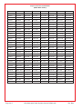
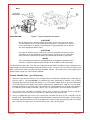
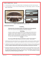
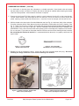
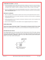
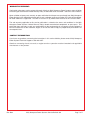
Service Bulletin
Compliance is Considered Mandatory
The technical content of this letter is FAA Approved
Bulletin No. 032
Issue Date: Mar. 13, 2008
INSPECTION OF CARBURETOR
THROTTLE VALVE PLATE SCREWS
INTRODUCTION:
It has come to the attention of Kelly Aerospace Power Systems that the two screws that secure the throttle
valve plate to the throttle valve shaft may not be of proper length (short). The subject screw KAPS part number
CF15-A23, has been sold as individual parts, in KAPS Carburetor Quick Kits, in KAPS Throttle Shaft Kits,
and may have been installed in certain carburetors overhauled by Kelly Aerospace Power Systems. The
screw length is important in that it must extend beyond the throttle shaft so that they may be “staked” to
secure them. Left uncorrected, the two screws that attach the throttle plate may back out The shortened
length will not allow proper compliance with Precision’s current overhaul manual.
This Service Bulletin is being issued to mandate the inspection for, and replacement of, short throttle valve
plate attachment screws KAPS P/N CF15-A23.
COMPLIANCE:
At the next regularly scheduled maintenance event or annual inspection but not to exceed the next
one hundred (100) hours time in service, the first to occur.
EFFECTIVITY:
Any aircraft utilizing: 1.) KAPS overhauled MA4-5 or HA-6 carburetor per the suspect serial number in the
table on the next page, 2.) Throttle Shaft Kit P/N CF778-1008, or Carburetor Quick Kit P/N CF286
(-05 through -11), as sold between September 29, 2006 and Jan. 29, 2008. or 3.) Incorporated CF15-A23
screw(s) into a throttle valve plate sold between September 29, 2006 and Jan. 29, 2008. Spare part (on
shelf) affectivity for the Carburetor Quick Kit or individual screw may be verified by confirming the proper
length of the P/N CF15-A23 screw(s) as indicated in the Disposition of Stock section page 6 Fig. 7.
NOTE::
The serial numbers listed in the Suspect Carburetor Serial Number Table on
the next page are for carburetors overhauled at KAPS using affected spare
parts. They are not inclusive of carburetors overhauled in the field using
KAPS Carburetor Quick Kits or individual CF15-A23 screws.
Rev. New
Kelly Aerospace Power Systems Service Bulletin 032
Page 1 of 7
Suspect Carburetor Serial Number
(Model MA4-5 & HA-6)
2-21-2540
75027805
BD-0-850
CL-0-173
CP-4-2570
DO-10-801
G-54-10759
K-7B-1041
3909602
75033602
BD-0-915
CL-0-234
CP-4-2743
DV-0-131
G-54-15104
K-7B-1207
3950435
75037410
BD-0-1298
CL-0-393
CP-5-3606
DV-0-148
G-55-11988
K-10-3982
3970193
75043319
BD-0-1736-R
CL-0-671
CP-5-4036
DV-0-179
G-55-12393
K-10-4013
3987108
75046721
BD-1-2164
CL-0-763
CP-5-4140
DV-1-1016
GL-0-739
K-10-4231
3990188
75066808
BD-1-2683
CL-0-918
CP-8-4175
DV-1-1046
H-17-2275
K-10-4411
3997894
75070602
BD-1-2787
CL-0-1059
CQ-1-100
DV-1-1187
H-17-2384
K-10-5352
3998656
75071825
BD-1-2920
CL-0-1165
CQ-2-159
DV-2-1264
H-11-4578
K-10-5509
4000857-R
75083723
BD-9-3188
CL-0-1587
CQ-3-215
DV-2-1322
H-11-4668
K-10-5596
4001219
75097608
BD-15-4551
CO-0-697
CQ-3-292
DV-2-1432
H-11-5661
K-25-64449
4001702
75100006
BD-15-4825
CO-0-919
CU-0-143
DV-2-1439
H-11-6513
K-27-6586
4002347
75110324
BD-15-4693
CO-0-995
DA-0-142
DV-3-2086
H-17-1311
K-28-6664
4002775
75115608
BD-16-5115
CO-0-1930
DA-0-169
EA-3-254
H-17-1716
K-41-7286
4002925
75120611
BD-17-5204
CO-0-2093
DE-0-119
G-5-9688
H-17-2178
K-41-7463
4006295
75123103
BD-23-6258
CO-0-2384
DE-2-447
G-6-1950
F-01-8103
K-42-7586
4009694
75135909
BD-23-6617
CO-3-2774
DE-4-1082
G-6-1969
H-17-2217
K-42-7786
4011811
75137310
BD-23-7201
CO-4-2903
DF-1-661
G-12-553
H-17-2320
K-42-8055
4011820
75392006
BD-24-8080
CO-4-2955
DG-0-458
G-12B-1779
H-17-2384
K-45-8357
4023318
75458706
BD-24-8201
CO-4-3131
DH-0-120
G-18-2887
H-17-2421
K-45-8466
4025807
75857112
BD-29-10012
CO-4-3463
DH-0-147
G-21-3374
H-19-2887
MA2985
4025971
75895812
BU-5-548
CO-4-3517
DL-0-539
G-28-3523
H-19-3351
O-38-4881
4026192
75991912
BU-15-1495
CO-4-3518
DL-0-155
G-32-4377
H-36-656
PAC-72-4909
75000403
A-27-8703
BU-15-1534
CO-4-3236
DL-0-879
G-34-4517
I- 27-8801
PAC-32-5410
75000404
AO-5-8702
BU-15-1677
CO-5-3760
DL-0-903
G-37-5933
K-0-58703
R-5-1690
75000405
AO-8-2374
BZ-2-782
CO-5-3835
DL-3-1071
G-44-6223
K-3-2227
R-5-2071
75004013
AO-15-2937
BZ-13-1639
CP-1-728
DL-4-1328
G-44-6279
K-3-2335
R-7-4056
75006716
AO-22-3707
BZ-19-3082
CP-1-990
DL-10-1619
G-49-1213
K-3-2989
R-9-4834
75009308
AO-38-5509
C-04-3012
CP-1-1437
DO-2-127
G-49-7436
K-3-3653
R-9-5593
75013204
AO-38-5532
C-34-4524
CP-1-1465
DO-2-201
G-50-7688
K-3-3830
RD-0-363
75015315
B-22-8805
C-51-9537
CP-1-9801
DO-4-210
G-50-8743
K-6-207
W-5-391
75017907
BD-0-675
CH-9-1503
CP-4-2179
DO-5-24G
G-51-1067
K-7B-839
W-5-325
75025402
BD-0-734
CH-9-1352
CP-4-2336
DO-5-229
G-51-9178
K-7B-975
Page 2 of 7
Kelly Aerospace Power Systems Service Bulletin 032
Rev. New
HA-6
MA4-5
PROCEDURE:
Figure 1 - Typical Carburetor Illustration
CAUTION::
Do not depend on this Service Bulletin for gaining access to the aircraft or engine.
This will require that you use the applicable manufacturers maintenance manuals or
service instructions. In addition, any preflight or in flight operational checks require
use of the appropriate AFM or POH.
CAUTION::
Any repair or overhaul work including that in this service bulletin on MA4-5 or HA-6
carburetors must be performed accordance with Precision Aircraft Carburetor
Service Manual FSMOH2 (for the MA4-5) or FSMOH4 (for the HA-6) as applicable.
NOTE::
The visual inspection procedure may be performed by a competent and qualified A & P
mechanic, or repairman experienced in maintenance of the MA4-5 or HA-6 carburetors.
This procedure has two steps. First, the visual inspection to determine if the MA4-5 or HA-6 carburetors have
proper length and staking of the throttle valve plate retaining screws. Second, the instructions to remove and
repair, or forward for repair, the MA4-5 or HA-6 carburetors affected. See caution above. See Suspect Serial
Number Table on page 2 for serial numbers affected.
VISUAL INSPECTION: (per Effectivity)
1. Determine if your aircraft is affected. This will require that you identify the carburetor serial number per the
table on page 2. You are affected if a carburetor has been overhauled or repaired using a KAPS
Carburetor Quick Kit P/N CF286 (-05 through -11), CF778-1008 Throttle Shaft Kit or have incorporated
CF15-A23 screw(s) into a throttle valve plate as sold between September 29, 2006 and Jan. 29, 2008.
Logbook verification is acceptable only if an overhaul was recorded properly for the time frame above or
if an affected serial number is recorded. Refer to Fig 1 for typical MA4-5 or HA-6 carburetor illustration.
2. Gain access to the carburetor by removing cowling, ducts as required. Utilize the aircraft and engine
manufacturers service manuals or instructions as applicable to your model aircraft.
3. Using an appropriate light source and magnification, examine the throat of the carburetor and the
throttle valve. Open throttle to full power so that the throttle valve plate will be fully open. Visually inspect
the bottom side of the throttle valve shaft to determine if the two screws are protruding and each staked
with a minimum of 3 peen marks at the end of the screw. See Figure 2 page 4.
Rev. New
Kelly Aerospace Power Systems Service Bulletin 032
Page 3 of 7
VISUAL INSPECTION: (Cont’d)
4. If the determination is that the screws are protruding and staked properly, proceed to step 9 on page 6.
5. If the determination is that the screws are not protruding and staked properly, proceed to “Carburetor
Repair” section below.
Cross Peen Stake
3 or 4 Peen Stake
Figure 2 - Throttle Plate Screw Protrusion & Stake
CARBURETOR REPAIR:
WARNING::
Take all precautions when removing, repairing, and installing the aircraft engine carburetor.
Aviation fuel may be uncontained or spilled creating noxious vapors and a potential fire
hazard. This may result in injury to personnel and damage to equipment.
CAUTION::
All repair or overhaul work must be performed in accordance with Precision Aircraft
Carburetor Service Manual FSMOH2 (for the MA4-5) or FSMOH4 (for the HA-6) as
applicable as well as these instructions. Any other or further repair of the carburetors
(MA4-5 or HA-6) must be performed by qualified personnel at a properly certificated part
145 repair station experienced with these specific carburetors.
NOTE::
Any and all carburetor repair work must be performed in accordance with the applicable
aircraft, engine or STC holders maintenance manual or instructions. (latest revision)
1. With the engine cowl already removed for access, preparation should be made to repair the carburetor. Special
tools should be obtained in compliance with the applicable Precision Aircraft Carburetor Service Manual.
2. Carburetor’s that fail the visual inspection above must be repaired. The repair consists of replacing and
staking the carburetor throttle valve plate retaining screws. This repair may be done in normal field service
or sent to a properly certificated part 145 repair station equipped to work on these specific carburetors.
3. Remove the carburetor per the applicable engine manufacturers service or maintenance manuals. When
removing the carburetor make sure engine is cold. Take care to limit fuel spillage. Drain residual fuel from
the carburetor bowl by removing the drain plug. Cap all fuel lines and cover openings. Observe and record
the idle setting and position of any carburetor control linkages. Be careful handling the empty
carburetor as the internal workings are delicate.
Page 4 of 7
Kelly Aerospace Power Systems Service Bulletin 032
Rev. New
CARBURETOR REPAIR: (Cont’d)
4. If a field repair is desired, place the carburetor on a suitable work table. Close throttle valve and remove
the two suspect screws and discard. Examine the shaft and thread for condition without moving the throttle
valve from closed position. Clean throttle shaft threads if required.
5. Prepare to install two CF15-A23 screws by applying a small amount of Loctite 271 on the screw threads.
Tap the closed throttle valve plate lightly to seat it in the bore. (It may be necessary to back out the idle
speed adjusting screw to allow fully closed valve.) Install the screws and torque each 10 to15 inch-lbs.
6. With the throttle valve closed, place Precision M100 arbor tool (see Fig. 3) in the throat (inlet) of the carburetor.
Place the carburetor with the arbor down on the table so the bottom of the throttle valve shaft is showing. (See
Fig. 5). Make sure the arbor is properly aligned with the shaft and using Precision M107 peening tool (see
Fig. 4), stake each screw with a light tap. DO NOT DAMAGE THE VENTURI OR SHAFT DURING THIS
OPERATION. Each screw must have three to four peening marks at the edge of the exposed screw threads.
Do not over peen. Fig. 6 shows an illustration from the Precision service manual showing the bowl removed.
Do not attempt this method in the field, it is recommended to be done only at a properly certificated 145
repair station.
Figure 3 - Precision M100
Throttle Valve Arbor Tool
Figure 4 - Precision M107
Throttle Valve Screw Peening Tool
7. Remove all caps and protective covers. Install and safety wire carburetor bowl drain plug. Be careful
handling the empty carburetor as the internal workings are delicate.
Figure 5 - Staking Carburetor Throttle Valve
Plate Screws (Field Repair)
Rev. New
Figure 6 - Staking Carburetor Throttle Valve
Plate Screws (145 Repair Station Only)
Kelly Aerospace Power Systems Service Bulletin 032
Page 5 of 7
CARBURETOR REPAIR: (Cont’d)
8. Utilizing the applicable aircraft and/or engine manufacturers maintenance manuals or service instructions,
re-install the repaired carburetor assembly. Connect all lines and linkages. Check and adjust as required
all linkages to the carburetor. Perform an inspection to check for security and leaks at the fittings.
9. Clean the carburetor induction duct to avoid contamination of the air inlet. Connect the inlet air ducts or
hoses per the applicable aircraft and/or engine manufacturers maintenance manuals or service instructions.
Check carburetor performance.
RETURN TO SERVICE:
1. With the carburetor assembly repaired or replaced, the aircraft may now be prepared for return to service.
2.
Utilizing the applicable aircraft and engine manufacturers maintenance manuals, perform an appropriate
engine performance run-up.
3.
Utilizing the applicable aircraft and engine manufacturers maintenance manuals, install any portion of the
aircraft removed to gain access.
4.
Upon successful completion of this service bulletin, make an appropriate log book entry of compliance.
PARTS REQUIRED:
Up to two (2) each per carburetor, part number CF15-A23 as required. Confirm that new CF15-A23 or 15-A23
screws are in compliance with Figure 7 below. If incidental parts are required in relation to this service
bulletin for the aircraft, engine or carburetor, they must be obtained from the applicable manufacturer.
DISPOSITION OF STOCK:
Any carburetor throttle valve screw, part number CF15-A23, Throttle Shaft Kit P/N CF778-1008, Carburetor
Quick Kit P/N CF286 (-05 through -11) which have been purchased from Kelly Aerospace Power Systems with
a procurement date between September 29, 2006 and Jan. 29, 2008 and remains in unused stock, may be
returned for replacement. If desired prior to return of any stock, screws may measured per the dimensions
shown in Fig. 7 using suitable measuring tools.
Figure 7 - KAPS P/N CF15-A23
Proper Screw Dimension
Page 6 of 7
Kelly Aerospace Power Systems Service Bulletin 032
Rev. New
WARRANTY STATEMENT:
Overhauled carburetors may be returned for repair directly to Kelly Aerospace Power Systems upon validation
of warranty per the overhaul Limited Warranty Policy included with each carburetor. See terms and conditions.
Upon validation of spare parts warranty, or upon verification that the part was purchased from Kelly Aerospace
Power Systems in the affected time frame, two (2) each carburetor screw, part number CF15-A23 will be allowed.
No labor allowance is applicable. This offer is valid for six (6) months from the date of this service bulletin.
The sole warranty applicable to this service publication is related to the terms and conditions in the Kelly
Aerospace Power Systems Limited Warranty Policy related to overhauled components or spare parts. This
publication does not imply or state any responsibility for the workmanship of any person or entity performing
work or maintenance on the carburetor, engine, or aircraft nor does it imply any responsibility for economic or
consequential loss.
CONTACT INFORMATION:
If you have any questions concerning the instructions in this service bulletin, please contact Kelly Aerospace
Power Systems Technical Support at 888-461-6077.
Questions concerning aircraft, rotorcraft, or engine service or operation must be forwarded to the applicable
manufacturer of that product.
Rev. New
Kelly Aerospace Power Systems Service Bulletin 032
Page 7 of 7