1
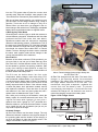
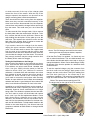
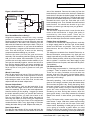
The Elec-Trak
Elec-Trak
Rides Again
Reviving G.E.’s Electric Lawn Tractors
Mike Bryce
©1999 Mike Bryce
Above: General Electric’s 20 horsepower Elec-Trak E20 on the left and the 10 horsepower E10 on the right.
T
he ’70s sure were exciting. We
saw the end of the Vietnam war,
Nixon and his Watergate, the Arab
oil embargo, Three Mile Island, and the
General Electric “Elec-Trak” riding lawn
tractors.
The Elec-Trak is a battery-operated lawn tractor. It was
produced by General Electric in the early ’70s. The
power of these tractors ranged from the small 8 hp E8
to the 20 hp E20, with several models in between. Each
tractor operated on a 36 volt DC system, supplied by
lead-acid batteries. The battery pack consisted of six 6
volt golf cart batteries, or in the case of the smaller E8,
three 12 volt batteries.
On the E8 and E10 tractors, the 36 inch (91 cm) mower
deck was suspended below the belly of the tractor. Two
36 volt mower motors each turned an 18 inch (46 cm)
mower blade. There were two blades and two mower
motors on each deck. Most of the larger models had the
mower deck out in front of the tractor, though some
were longer in order to hold the mower deck under the
tractor ’s belly. In either case, the cut width was
increased to 42 inches (107 cm), using three motors
driving three cutting blades.
44
Home Power #70 • April / May 1999
Along with increases in horsepower, the larger models
grew in complexity. Many of them had an electric lift
motor to raise or lower the front-mounted mower deck.
This lift motor could also raise and lower the snow
blower. Why, the E20 even came with cruise control!
Attachments
The entire line of Elec-Traks ran on 36 volts DC. You
could purchase many attachments for the tractors,
including a chain saw and a DC to AC rotary inverter.
There was a snow blower and a tiller that would plug
Below: This beat-up E10 still works like a charm.
Go Power
into the PTO (power take-off) that the mower deck
normally used. With such foresight, many people in the
’70s said the Elec-Trak was 20 years ahead of its time!
With one of these electric tractors, you could mow your
yard and then trim the hedges without using a drop of
gasoline. There was no oil to change or dirty oil to
discard. When you were done, you plugged in the onboard charger and set the timer. Recharging a depleted
battery bank required about twelve to eighteen hours.
A Rose by Any Other Name
General Electric sold the rights to build their tractors to
several different companies. Wheelhorse and New Idea
produced the Elec-Trak under their own labels.
Wheelhorse models were red, and used a completely
different model-naming scheme. A Wheelhorse C145 is
the same as a General Electric E15. New Idea changed
the color scheme to orange and cream. Under the New
Idea brand, the tractors were called EGT or Electric
Garden Tractors. Although the basic tractor remained
the same, each supplier made various changes in the
circuitry and mechanics of the machines.
The E10 can be broken down into four main
components: battery charger, main drive motor, PTO,
and mechanical subassemblies. If you find an E10, it’s
a good bet that the battery bank is kaput! The batteries
in my E10 were fourteen years old. Remove a few
battery caps and check for water. If the cells are empty
or below the plates, don’t add water. Instead, remove
and replace the batteries. There are three 6 volt golf
cart batteries in the front and three under the seat. I
replace worn out batteries with Trojan T-105s.
Also, while you’re working on the batteries, check the
battery cables for cracked ends and burnt wires. The
original E10 came with 6 gauge (13 mm 2 ) wire. I
replaced mine with 4 gauge (21 mm2) stranded wire.
Mark the cables so you know what went where. It’s best
not to install the new set of batteries just yet, as you
may need to repair the charger.
On-board Charger
All Elec-Trak tractors use the same charger. The only
differences between models are the physical shape of
the mounting plate and the location of the charger. In
our E10, the charger is under the steering column. The
charger’s schematic is shown in Figure 1.
Above: Donna’s hedge trimmer plugs directly into
this E15 Elec-Trak.
All Elec-Trak chargers work the same. The heart of the
charger is the specially wound ferro-resonant
transformer. The output of the transformer is routed to
two large diodes mounted on a heat sink. The
transformer, along with a capacitor, regulates the
current flow into the battery bank. To prevent
overcharging the batteries, a motor-driven timer
switches the charger off. No electronics are used to
control the charging current to the battery bank.
Figure 1: E10 Charger Circuit
Timer
Line plug
M
Transformer
Elec-Trak E10
Because of the sheer numbers of E10s produced, you
are more likely to run into one of these than any other
Elec-Trak. Also, of all the different models, the E10 is by
far the easiest to get back into working condition. Plan
to pay from nothing to about $200 for a used E10.
Prices will vary of course, depending on the condition of
the basic tractor and battery bank.
CR5
CR4
CP2
Fuel level gauge
Circuit breaker
CB-2
–
+
Accessory
receptacle
Power pack
Home Power #70 • April / May 1999
45
Go Power
the charger and the batteries. If this
circuit breaker trips when the
charger is unplugged, but with
batteries in the circuit, then both
diodes are shorted or there is a
external short between the batteries
and the charger.
No hum from the transformer and no
output usually means a defective
timer switch or connector. It’s also
possible to have an open primary
winding on the transformer, but
that’s rare. Pay attention to the wires
leading to and from the timer switch.
These tend to fall off, shutting down
the charger. Also, the wires coming
out of the transformer will be brittle
due to heat and old age. Use care
when handling them.
Fixing the Charger
If one or more of the above tests
indicates a faulty charger, the
Above: The three motors on the out-front mower deck of an E20.
charger must be removed from the
tractor for repair. The only way to get to the charger is
By using a clamp-on DC amp probe and a Fluke 73
by removing the front two batteries. If the battery
meter, I measured over 21 amps of charging current
compartment is badly corroded, then all three batteries
flowing into the batteries after a mowing job. After ten
must be removed to make extra room for the hammers
hours or so, the charging rate drops to about 10 amps.
and pry bars you’ll need! There is a plastic tray on the
The finished charge current levels off at 6 amps. The
bottom of the front compartment. Remove this tray by
bank of six batteries are wired in series for a 36 volt
pulling it out. Be mindful of flying crud. Eye protection is
system with 220 amp-hours of storage. A complete
a must!
sixteen-hour charge would be equal to about 10 KWH.
Testing the On-board Charger
You can test the charger without removing it from its
hiding spot. With the batteries removed, connect your
voltmeter to the positive and negative battery cables.
Plug in the charger and move the timer knob past the
“start” position. You should hear a loud hum from the
transformer and read at least 39 volts on your meter. If
you do, then the charger is working correctly.
However, if your meter reads 20 volts or so, then one of
the diodes has opened. If the meter reads about 30
volts, the capacitor is defective. On two different
occasions, I’ve found one of the wires leading to the
capacitor had fallen off. Since these tractors take such
a beating, look for loose wires before digging too deep.
If the transformer growls loudly, and the voltmeter reads
zero, quickly unplug the charger. One or both of the
diodes may be shorted, or there might be a rare short
circuit on the battery side of the charger. There are no
breakers or fuses on the AC input side of the charger. A
50 amp circuit breaker on the battery side is supposed
to protect the charger in case of a short circuit between
46
Home Power #70 • April / May 1999
With the plastic tray out, you’ll need to remove three
bolts on each side of the tractor. These bolts hold the
charger mounting plate to the tractor’s body. The
bottom two bolts will probably be too corroded to be
used again. Replace the hardware with stainless steel
bolts and nuts when you reassemble the unit. With all
Below: The timer control knob is clearly visible on
the E20 charger. The PTO socket is at lower left.
Go Power
six bolts removed, tilt the top of the charger plate
toward the front of the tractor. With the top of the
charger exposed, the capacitor can be seen on the
charger mounting plate, beside the transformer.
There should be two wires coming from the capacitor.
Make sure they are both connected securely. If the
wires have become disconnected from the capacitor,
connect them and retest the charger before removing it
from the tractor. This could save you a lot of time and
effort.
To make removal of the charger easier, I like to remove
the deck plate under the transmission shift lever. To do
this, unscrew the ball from the shift lever. Remove the
bolts holding the deck plate. Lift the plate up over the
shift lever. This exposes the main drive motor and the
back side of the charger. Now it’s easier to access the
wiring harness leading to the charger.
If you need to remove the charger from the tractor,
unplug the nylon connector leading from the timer
motor. You will also need to remove the negative lead
from the post on the charger and the positive lead
connected to the heat sink. With these wires removed,
you can take the charger out of the tractor. This sounds
easy enough, but there may be enough corrosion from
the battery acid to make it a struggle.
Testing for Bad Diodes on the Charger
One or both of the diodes on the heat sink may be no
good. There are two wires coming from the transformer
to the diodes, one wire to each diode. Unsolder both
wires. Use your VOM (volt-ohm meter) to find the
defective diode. With your VOM set to measure
resistance, a shorted diode will read about zero ohms
from cathode to anode, and zero ohms from anode to
cathode too. Since a diode is like a one-way valve,
you’ll need to reverse the test probes while checking
diodes. An open diode will show infinite ohms between
cathode and anode. A good diode will show about 500
ohms in one direction and about 25 ohms in the other.
Above: The E20 charger removed from the tractor,
showing the heat sink with two diodes, capacitor,
and transformer.
Of all the Elec-Traks I’ve repaired, I’ve found only one
with a cooked transformer. This one died because one
of the diodes had shorted and the user kept on trying to
charge the batteries. When I find a dead charger, nearly
80 percent of the time the problem is a defective diode
on the heat sink.
To test the repaired charger, plug the connector from
the timer motor into the charger. Apply power to the
charger, and turn on the timer. Take your reading from
the heat sink (positive) to the center tap of the
transformer (negative). The center tap is fastened to the
large stud near the heat sink. You should see 39 to 41
Below: The opened access panel on an E10.
The larger relay on the right is the PTO contactor.
According to an old General Electric service manual, a
defective diode means replacing the entire heat sink
assembly. However, these assemblies are no longer
being made. The diodes are pressed into the heat sink.
You don’t want to punch out the diodes and replace
them, even if you can find replacement diodes. I leave
both diodes alone, although one or both may be
defective, and install two new 35 amp diodes. Drill a
new hole for the replacement diodes on the heat sink,
and use 1N1188A diodes. To help transfer heat from the
diodes to the metal heat sink, use silicone heat sink
compound, available at Radio Shack or through Hosfelt
Electronics.
Home Power #70 • April / May 1999
47
Go Power
volts if everything is working correctly. Before you install
the charger, clean out any crud you see.
Main Drive Motor
The E10 uses a very simple drive motor and control
circuit. The drive motor is a permanent magnet motor
about the size of a large thermos. There are no special
circuits used to reverse the drive motor or to change its
speed. That’s all done by the Peerless transmission.
We only need to apply power to the drive motor to get it
spinning. The motor start circuit for the E10 is shown in
Figure 2.
Start Circuit
Three things must happen to allow the main contactor
(“L” in the schematic) to pull in. First, the key switch
must be on. Then the operator must be on the seat,
closing the seat switch. Finally, the clutch/brake pedal
must be depressed, operating the clutch switch. With
the clutch pedal depressed, the drive belt is prevented
from transferring power from the motor to the
transmission. This allows you to start the tractor without
being thrown off the seat!
Once the contactor pulls in, a separate set of contacts
seals the contactor in. You can then remove your foot
from the clutch and drive off. Turning the key switch off
or getting off the seat will unseal the contactor, stopping
the drive motor. To restart the tractor, you must depress
the clutch and reset the key switch to seal the contactor
again. The operator, of course, has to be in the seat!
Some Quick Tests for the Drive Motor
If you have removed the plate under the shift lever, the
drive motor will be fully exposed. On the rear of the
motor, you’ll find the two armature terminals. One is
connected to the negative battery lead. The other one
runs back up to the main contactor located behind the
steering column. To access this contactor, remove the
two screws holding the cover panel in place. There is
enough wire slack to allow the cover panel to lie flat.
Place a piece of cardboard on top of the batteries if
they are installed. This will prevent the cover panel from
shorting out the battery terminals.
First either put the transmission in neutral, remove the
drive belt from the pulleys, or jack up the rear end so
the wheels are off the ground and block them. To verify
that the drive motor works, check it with a 12 volt
battery. Connect the tractor’s negative battery cable to
the negative post of the battery. Connect a heavy-duty
clip lead to the positive battery post. Then briefly touch
the other end of the lead to the contactor (“L”) cable
that goes to the main drive motor. If there are no
problems with the drive motor, it will start spinning. This
simple test shows whether the drive motor is working or
not.
48
Home Power #70 • April / May 1999
Figure 2: E10 Start Circuit
Circuit breaker
CB-3
AA model only
Clutch
switch
L “A”
L “B”
L coil
+
Power
pack
Fuel level
gauge
Circuit breaker
CB-1
Seat switch
Drive
motor
–
Connector
for model
26AEIOAA
Key switch
If you tested the drive motor with the external power
source and the motor runs, the problem is in one of the
control switches. In rare cases, you may have an open
contactor coil. All electrical connections must be tight.
Check for tightness at the main contactors and PTO
contactors. These tractors shake and rattle, so loose
wires are common.
The seat switch is the first one that ends up being
defeated by the user, so look under the seat for a
switch. It should be mounted on the cross member
holding the small seat spring. If the switch is there, but
you see no wires coming from the seat, look for them
taped together somewhere in the battery compartment.
Battery acid and water may have eaten away at the
wires, preventing the motor from starting.
Check the clutch switch as well. It’s located on the right
side of the tractor under the transmission. With the
clutch, seat, and key switches on, you should measure
36 volts across the contactor’s coil. If you do get 36
volts but the contactor does not pull in, the coil is bad
and needs to be replaced.
PTO Circuit
On the E10, the PTO circuit works almost exactly the
same way as the motor drive circuit, minus the clutch
and seat switches. When the PTO start switch is moved
to the start position, it seals in the PTO coil. This allows
the spring-loaded switch to move to the run position.
The mower motors are permanent magnet motors.
When the PTO switch is turned off, the PTO contactor
shorts out the mower motors, dynamically stopping the
motors.
Mechanical Subassemblies
All of the mechanical subassemblies are very basic and
straightforward. It’s beyond the scope of this article to
cover all the details. A good dose of common sense will
be your best guide. If it looks like it needs oil, then oil it.
If you see a grease fitting, grease it. Check for wear
and tighten loose fasteners. A few of the more common
problems are discussed here, with suggestions on how
to deal with them.
Go Power
Figure 3: E10 PTO Circuit
Circuit breaker
CB-3
AA model only
Clutch
switch
L “A”
Start
L coil
+
Power
pack
–
Circuit breaker
CB-1
Seat switch
Key switch
PTO “C”
J1
Run
Off
PTO coil
J2
Don’t Know Where You’re Going?
Stripped-out steering columns are a very common
problem in these tractors. What happens is that the
steering shaft and pinion gear wear down the gear and
sector assembly. If the wear is not excessive, you can
add some shim washers to take up the slack. This job is
messy and labor intensive. If you have all the batteries
out of the tractor, I suggest you tilt the tractor over on its
side. This will allow you to work on the steering
components without standing on your head.
Remove the cotter pin from the gear and sector
assembly. Pull the steering shaft and pinion gear away.
Add your shim washer and reassemble. Try the fit. If
you have too much slop, add more shim washers. If you
can’t get the assembly together, remove one shim at a
time until the steering pinion and sector assembly are
nice and tight. Replace the cotter pin with a roll pin and
finish up with a nice glob of grease on both gear
surfaces.
Whoa! I Can’t Stop!
Don’t flip the tractor over just yet. Did you check to see
if your brakes work? Now is the best time to work on
them since the tractor is on its side. There are two basic
brake designs used on the Elec-Trak, the die-cast
caliper brake and the steel caliper brake.
Die-cast Caliper Brake
On the transmission, you’ll see the brake disk. If you
have the die-cast caliper, there will be a small nut and
cotter pin assembly. This nut is the brake adjustment.
However, before you do anything, I suggest you watch
the brake assembly while you operate the brake by
hand. If nothing moves, you have lots of work to do.
Plan on using plenty of WD-40! Adjust the brake by
removing the cotter pin and turning the adjustment
screw until it’s finger tight. Back off the adjustment
counterclockwise until a very slight drag is felt when
rotating the brake disk by hand. Replace the cotter pin.
Steel Caliper Brake
First jack the rear wheels off the ground and block the
front wheels. Then remove the rear wheel on the brake
side of the transaxle. Remove the cotter pin from the
brake clevis pin, then remove the clevis pin. Rotate the
brake clevis to shorten the brake linkage until the brake
drags, then back off one-half turn. The clevis and clevis
pin must be reinstalled temporarily to check brake drag.
Reinstall the clevis, clevis pin, and cotter pin on the
brake actuating lever. Then reinstall the wheel and test
brake function. You should now be able to go in the
direction you want to go, and stop once you get there!
Main Drive Belt
The E10 has a single drive belt. It runs from the drive
motor to the transmission. A single idler pulley is
controlled by the clutch pedal. There are no
adjustments to take up any slack from a worn belt. If the
main drive belt slips, then the belt must be replaced.
Finding Parts and Supplies
I have had no contact with General Electric, and they
no longer supply parts for the Elec-Trak. A local tractor
dealer here has been very helpful. They used to sell
these tractors, but don’t have the time to deal with
inquiries.
The diodes are available from Hosfelt Electronics or
Mouser Electronics, among others. Any local golf cart
supply house will sell you coils and relays. The belts are
common Gates products, which any mower shop will be
able to replace. I would be more than happy to help
readers find sources for parts, and assist with any ElecTrak problems.
Life with an Elec-Trak
The first thing everyone asks is, “How long will it run on
a charge?” That’s a question that is hard to answer!
There are so many variables one must take into
account. How tall is the grass? Are the blades sharp?
How fast will your forward speed be? What kind of
grass will you be cutting?
Generally speaking, I can cut about three acres of
grass on one charge, provided I keep the blades sharp
and cut when the grass is dry. During the spring, when
the grass is thicker, I have to reduce my forward speed
to cut the grass cleanly. Going too fast through high
grass will cause excessive current to be pulled,
shortening run time. During late summer, when the
grass grows slowly, I can really increase the forward
speed of the tractor. In other words, your mileage may
vary!
On my E20 tractor, with a mower motor idling, a single
motor draws 7 amps. With three mower motors sitting
there running, that’s a hair over 20 amps. Drive motor
current varies, depending on what gear you’re in and if
you’re going up or down a grade. When you start
putting a load on the mower motors, the current will
increase. It would be interesting to know just what these
Home Power #70 • April / May 1999
49
Go Power
machines draw under load. But I decided that it would
be unsafe to try measuring motor current while mowing
the back forty!
All Elec-Trak tractors come with an analog voltmeter
that serves as a “fuel gauge.” I have found huge
differences in meter accuracy. The higher end models
also come with a “load meter” that monitors current
draw from the battery bank. It’s fun to watch the load
meter increase as the tractor heads uphill!
What Happened to the Elec-Trak?
Why did the Elec-Trak die out? I really don’t know.
Perhaps it was the expense of replacing the battery
pack every several years. A life span of three to five
seasons is about all you can expect from the batteries.
To replace the battery pack, it cost up to $450. And of
course, you can’t mow twenty acres on one charge,
either.
With an increased dependence on imported oil, the
Elec-Trak may be making a comeback. New laws
governing emissions from small IC engines may also
spark renewed interest in the Elec-Trak. If you can find
50
Home Power #70 • April / May 1999
one, put an Elec-Trak back to work. There’s nothing
quite like mowing your yard while listening to the birds
singing in the trees. That’s something you can’t do
unless you’re riding on a General Electric Elec-Trak!
Access
Author: Mike Bryce, SunLight Energy Systems,
955 Manchester Ave SW, North Lawrence, OH 44666
330-832-3114 • Fax: 330-832-4161
[email protected] • www.seslogic.com
Hosfelt Electronics, 2700 Sunset Blvd., Steubenville,
OH 43952-1158 • 888-264-6464 • 740-264-6464
Fax: 800-524-5414 • [email protected]
www.hosfelt.com
Mouser Electronics, 2401 Hwy 287 N, Mansfield, TX
76063 • 800-346-6873 • 817-483-6852
Fax: 817-483-0931 • [email protected]
www.mouser.com
Trojan Battery Company, 12380 Clark Street, Santa Fe
Springs, CA 90670 • 800-423-6569
Fax: 562-906-4033