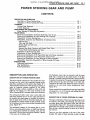
1
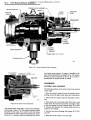
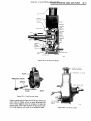
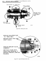
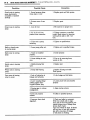
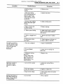
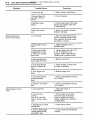
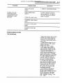
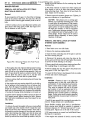
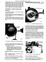
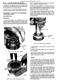
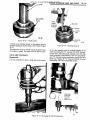
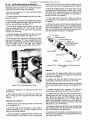
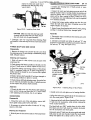
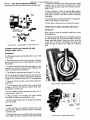
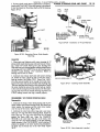
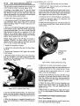
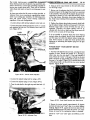
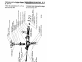
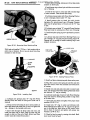
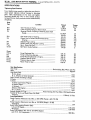
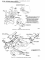
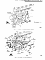
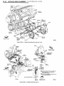
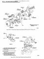
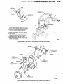
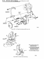
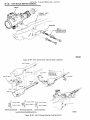
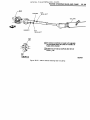
POWER STEERING GEAR AND PUMP
www.TeamBuick.com
3F- 1
POWER STEERING GEAR AND PUMP
CONTENTS
DESCRIPTION AND OPERATION:
Description of Power Steering Gear
Description of Power Steering Oil Pump
3F- 1
3F- 1
DIAGNOSIS:
External Leak Diagnosis
Trouble Diagnosis
MAINTENANCE AND ADJUSTMENTS:
3F- 2
3F- 5
Power Steering Oil Pump Belt Adjustment
3F-11
Removal and Installation of Pitman Shaft Seals, Gear in Car
Removal and Installation of Power Steering Gear Assembly
Disassembly of Power Steering Gear
Disassembly, Inspection and Reassembly of Individual Units
3F-12
3F-12
MAJOR REPAIR:
3F-13
Adjuster Plug
Valve and Stub Shaft
Pitman Shaft and Side Cover
Rack-Piston
3F-14
3F-15
3F-17
3F-17
Steering Gear Hose Connector and Poppet Check Valve
Pitman Shaft Needle Bearing and Seals
3F-18
3F-18
Reassembly of Power Steering Gear
Adjustments of Power Steering Gear
3F-19
3F-20
Removal and Installation of Oil Pump Shaft Seal with Pump Assembled
Removal and Installation of Oil Pump Flow Control Valve
Removal and Installation of Power Steering Oil Pump Assembly
Disassembly, Inspection, Reassembly of Power Steering Oil Pump
3F-24
3F-24
3F-24
3F-25
Tightening Specifications
Gear Specifications
Pump Specifications
3F-28
3F-28
3F-28
SPECIFICATIONS:
DESCRIPTION AND OPERATION
DESCRIPTION OF POWER STEERING GEAR
The major internal components of the variable ratio steer
ing gear are the rotary valve assembly steering worm,
rack-piston assembly, and the pitman shaft, Figure 3F-1.
The movement of these parts, while turning or parking, is
aided by hydraulic pressure supplied by the pump.
Manual steering is always available at times when the
engine is not running, or in the event of pump or belt
failure. Steering effort is increased under such conditions.
The hydraulic rotary valve is concentric with the input
shaft and is contained in the upper section of the gear
housing. It contains a spool that is held in neutral position
by means of a torsion bar. The spool is attached to one end
of the torsion bar and the valve body to the other end.
Twisting of the torsion bar allows the spool to rotate in
relation to the valve body, therby operating the valve.
Figure 3F-2.
Under normal driving conditions the steering wheel effort
will range from 1 to 1-1/2 pounds, and parking effort will
range from 2 to 2-1/2 pounds.
The steering stub shaft, rotary valve, worm shaft, and
rack-piston assembly are all "in line". The rack-piston in
the variable ratio steering gear is modified to accommo
date the larger center tooth on the pitman shaft gear. All
oil passages are internal within the gear housing, except
for the pressure and return hoses between the gear and the
pump. Figure 3F-1.
The mechanical element of this steering gear is a lowfriction, recirculating ball system, in which steel balls act
as a rolling thread between the steering worm and the
rack-piston. The one-piece rack-piston assembly is geared
to the sector of the pitman shaft.
DESCRIPTION OF POWER STEERING OIL PUMP
The major components of the power steering pump are the
oil reservoir, drive shaft, pump housing, cam ring, pres
sure plate, thrust plate, flow control valve, and rotor and
vane assembly, Figure 3F-3. The pump housing and com
ponent parts are encased in the oil reservoir. The reservoir
filler cap has a dipstick attached to show the oil level in
the reservoir.
There are two bore openings at the rear of the pump
housing. The larger of these openings contains the cam
3F- 2
www.TeamBuick.com
1975 BUICK SERVICE MANUAL
ROTARY VALVE ASSEMBLY -
RACK-PISTON NUT
WORAA-
ADJUSTER
BACK-UP^
PLUG
O-RING
STUB SHAFT
UPPER
THRUST
BEARING
LOWER
THRUST
BEARING
-SNAP RING (B-C-E- SERIES)
PITMAN SHAFT
3F-1
Figure 3F-1 Power Steering Gear Cutaway
rVALVE BODY CAP
fPRESSURE PORT
-SPRING
RETURN PORT //-DAMPER O-RING
TORSION BAR
O-RING SEAL
valve limits pump pressure. A magnet is installed in the
pump housing attached by its magnetic force. The magnet
will pick up metal impurities in the oil. If the pump is
disassembled the magnet should be cleaned.
DIAGNOSIS
EXTERNAL LEAK DIAGNOSIS
The following method can be used to locate most external
system leaks:
TORSION
BAR
I-VALVE SPOOL
Figure 3F-2 Rotary Valve Assembly
ring, pressure plate, thrust plate, rotor and vane assembly,
and end plate. Figure 3F-3. The smaller opening contains
the pressure line union, flow control valve, and spring.
The flow control orifice is part of the pressure line union.
Figure 3F-4. A pressure relief valve inside the flow control
1. With the vehicle's engine off, wipe the complete power
steering system dry (gear, pump, hoses and connections).
2. Check oil level in pump's reservoir and adjust if neces
sary.
3. Start engine and turn steering wheel from stop to stop
several times. Do not hold in corner for any length of time
as this can damage the power steering pump. It is easier
if someone else operates the steering wheel while you
search for the seepage.
4. Find the exact area of leakage. See Figures 3F-5, 3F-6,
and 3F-7.
5. Make the correct repair to stop the leak.
www.TeamBuick.com
POWER STEERING GEAR AND PUMP
3F- 3
PRESSURE UNION
Figure 3F-3 - Oil Pump Cutaway
HIGH OIL
OR CAP
LEVEL
LEAKING
RESERVOIR "O" RING
PRESSURE UNION
.FLOW-CONTROL
VALVE
4B3F4
Figure 3F-4 - Flow Control Valve
Leaks occuring near the upper end of the gear (where the
rotary valve is visible) are not as easily pinpointed and
more intense diagnosis may be necessary to make the
correct repair. Due to the closeness of the various seals,
the wrong diagnosis will result in an ineffective repair.
HOSE FITTING
OR "O1 RING
SEALS
Figure 3F-5 - Oil Pump Leaks
3F- 4
www.TeamBuick.com
1975 BUICK SERVICE MANUAL
SIDE COVER "O" RING SEAL
HOSE FITTINGS
ROTORY VALVE
ASSEMBLY OR
SNUB SHAFT
SEAL
END PLUG
"O" RING SEAL
PITMAN SHAFT
SEALS
3F-14
Figure 3F-6 - Steering Gear Leaks
REPLACE ADJUSTER PLUG
"O"
RING SEAL
REPLACE DUST AND STUB
SHAFT SEALS.
REPLACE ROTARY VALVE
ASSEMBLY
SEAT BALL FLUSH WITH
PUNCH AND RESTAKE. IF
SEEPAGE PERSISTS, REPLACE
HOUSING
3F-15
Figure 3F-7 - Upper End Steering Gear Leaks
TROUBLE DIAGNOSIS
www.TeamBuick.com
POWER STEERING GEAR AND PUMP
This paragraph covers only those causes of trouble which
may be due to the hydraulic power mechanism. Causes
which are due to the steering linkage and front suspension
are the same as described for standard steering gear.
Condition
Hissing noise in steering
gear.
Possible Cause
1. There is some noise in
all power steering sys
tems. One of the most com
mon is a hissing sound
most evident at standstill
parking.
There is no relationship
between this noise and
performance of the steer
ing. "Hiss" may be ex
pected when steering wheel
is at end of travel or
when slowly turning at
standstill.
Correction
1. Slight "hiss" is normal and in no
way affects steering. Do not re
place valve unless "hiss" is ex
tremely objectionable. A replacement
valve will also exhibit slight noise
and is not always a cure for the ob
jection. Investigate clearance
around flexible coupling rivets.
Be sure steering shaft and gear are
aligned so flexible coupling rotates
in a flat plane is not distorted as
shaft rotates. Any metal-to-metal
contacts through flexible coupling
will transmit valve "hiss" into pas
senger compartment through the
steering column.
Rattle or Chuckle noise
in steering gear.
1. Gear loose on frame.
1. Check gear-to frame mounting
screws. Tighten bolts to
specifications.
2. Steering linkage
looseness.
wear. Replace if necessary.
3. Pressure hose touching
other parts of car.
bend tubing by hand.
4. Loose pitman shaft over
4. Adjust to specifications.
2. Check linkage pivot points for
center adjustment.
A slight rattle may oc
3. Adjust hose position. Do not
cur on turns because of
increased clearance off
the "high point". This is
normal and clearance must
not be reduced below
specified limits to elimi
nate this slight rattle.
Squawk noise in steering
gear when turning or re
covering from a turn.
1. Dampener "O"
valve spool cut.
Chirp noise in steering
1. Loose belt.
1. Adjust belt tension to
specification.
Belt squeal (particu
larly noticeable at full
wheel travel and stand
1. Loose belt.
1. Adjust belt tension to
specification.
Growl noise in steering
1. Excessive back pres
sure in hoses or steering
1. Locate restriction and correct.
Replace part if necessary.
ring on
pump.
1. Replace dampener "O" ring.
still parking).
pump.
gear caused by re
striction.
3F- 5
3F- 6
www.TeamBuick.com
1975 BUICK SERVICE MANUAL
Correction
Condition
Possible Cause
Growl noise in steering
pump (particularly
noticeable at standstill
parking).
1. Scored pressure plates,
thrust plate or rotor
1. Replace parts and flush system.
2. Extreme wear of cam
ring.
2. Replace parts.
1. Low oil level.
1. Fill reservoir to proper level.
2. Air in the oil. Poor
pressure hose connection.
2. Tighten connector to specified
torque. Bleed system by operating
steering from right to left - full
Groan noise in steering
pump.
turn.
3. Loose bolt in pump
mounting.
3. Tighten to specifications.
Rattle or knock noise
in steering pump.
1. Loose pump pulley nut.
1. Tighten nut to specified torque.
Rattle noise in steering
1. Vanes not installed
properly.
1. Install properly.
2. Vanes sticking in rotor
slots.
2. Free up by removing burrs,
varnish or dirt.
L Malfunctioning flow
valve.
1. Replace part.
pump.
Whine noise in steering
1. Pump shaft bearing
1. Replace housing and shaft.
Flush system.
1. Lack of lubrication in
linkage and ball joints.
1. Lube linkage and ball joints.
2. Lower coupling flange
rubbing against steer
ing gear adjuster plug.
2. Loosen pinch bolt and assembly
properly.
3. Steering gear to column
misalignment.
3. Align steering column.
4. Tires not properly
inflated.
4. Inflate to specified pressure.
5. Improper front wheel
alignment.
5. Check and adjust as necessary.
With front wheels still on align
ment pads of front-end machine, dis
connect pitman arm of linkage from
pitman shaft of gear.
Turn front wheels by hand. If wheels
will not turn or turn with consider
able effort, determine if linkage
or ball joints are binding.
pump.
Switch noise in steering
pump.
Poor return of steering
wheel to center.
www.TeamBuick.com
POWER STEERING GEAR AND PUMP
Condition
Possible Cause
Correction
6. Steering linkage
binding.
6. Replace pivots.
7. Ball joints binding.
7. Replace ball joints.
(Turn steering wheel and
listen for internal rub
bing in column - check
causes listed and correct
as directed).
8. Steering wheel rubbing
against directional signal
housing.
8. Adjust steering jacket.
9. Tight or frozen steer
ing shaft bearings.
9. Replace bearings.
10. Rubber spacer binding.
10. Make certain spacer is properly
seated. Lubricate inside diameter
with silicone.
11. Sticky or plugged valve
Car pulls to one side or
the other. (Keep in mind
road condition and wind.
Test car on flat road
going in both
directions).
11. Remove and clean or replace
spool.
valve.
12. Steering gear adjust
ments tight.
12. Check adjustment with gear out
of vehicle. Adjust as required.
1. Front end misaligned.
1. Adjust to specifications.
2. Tire pull (Radial
Tires).
2. Check tires for running true
under load.
3. Unbalanced steering
3. Replace valve.
gear valve.
If this is cause, steer
ing effort will be very
light in direction of
lead and heavy in op
posite direction.
Momentary increase in
effort when turning
wheel fast to right or
left.
Steering wheel surges or
jerks when turning with
engine running, especial
ly during parking.
1. Low oil level in pump.
1. Add power steering fluid as
required.
2. Pump belt slipping.
2. Tighten or replace belt.
3. High internal leakage.
3. Check pump pressure (see pump
pressure test).
1. Low oil level.
1. Fill as required.
3F- 7
3F- 8
www.TeamBuick.com
1975 BUICK SERVICE MANUAL
Condition
Excessive wheel kick
back or loose steering.
Possible Cause
Correction
2. Loose pump belt.
2. Adjust tension to specification.
3. Steering linkage hit
ting engine oil pan at
full turn.
3. Correct clearance.
4. Insufficient pump
pressure.
4. Check pump pressure. (See pump
pressure test). Replace relief valve
if malfunctioning.
5. Sticky flow control
valve.
5. Inspect for varnish or damage.
Replace if necessary.
1. Air in system.
1. Add oil to pump reservoir and
bleed by operating steering. Check
hose connectors for proper torque
and adjust as required.
2. Steering gear loose on
frame.
2. Tighten attaching screws to
specified torque.
3. Steering gear flexible
coupling loose on shaft
or rubber disc mounting
screws loose.
3. Tighten flange pinch bolts to 30
ft. lbs., if serrations are not
damaged. Tighten upper flange to
coupling nuts to specified torque.
4. Steering linkage joints
worn enough to be loose.
4. Replace loose pivots.
5. Front wheel bearings
incorrectly adjusted or
5. Adjust bearings or replace with
new parts as necessary.
worn.
Hard steering or lack of
assist.
6. Worn poppet valve
(gear).
6. Replace poppet valve.
7. Loose thrust bearing
preload adjustment
(gear).
7. Adjust to specification with gear
out of vehicle.
8. Excessive "over-center"
lash.
8. Adjust to specification with gear
out of vehicle.
1. Loose pump belt.
1. Adjust belt tension to
specification.
2. Low oil level in
reservoir.
Low oil level will also
result in excessive pump
noise.
2. Fill to proper level. If exces
sively low, check all lines and
joints for evidence of external
leakage. Tighten loose connectors
to specifications.
3. Steering gear to column
misalignment.
3. Align steering column.
4. Lower coupling flange
rubbing against steering
gear adjuster plug.
4. Loosen pinch bolt and assemble
properly.
www.TeamBuick.com
POWER STEERING GEAR AND PUMP
Condition
If checks 1-5 do not
reveal cause of hard
steering, follow the pro
cedure below to deter
mine fault
Possible Cause
Correction
5. Tires not properly
inflated.
5. Inflate to recommended pressure.
Further possible causes
In order to diagnose conditions
such as listed in 6, 7, 8, and 9, a
test of the entire power steering
system is required.
could be:
6. Sticky flow control valve.
7. Insufficient pump pressure
output.
8. Excessive internal pump
leakage.
9. Excessive internal gear
leakage.
POWER STEERING SYSTEM
TEST PROCEDURE
1. Disconnect pressure hose at union
of pump, use a small container to
catch any fluid which might leak.
2. Connect a spare pressure hose to
pump union.
3. Using Pressure Gauge J-5176-1,
Adapter Fitting J-22326, connect
gauge to both hoses.
4. Open hand valve on gauge.
5. Start engine, allow system to
reach operating temperatures and
check fluid level, adding any fluid
if required. When engine is at
normal operating temperature, the
initial pressure read on the gauge
(valve open) should be in the 80-125
PSI range. Should this pressure be
in excess of 200 PSI, check the
hoses for restrictions and the pop
pet valve for proper assembly.
6. Close gate valve fully three
times. Record the highest pressures
times. Record the highest pressures
attained each time. Do not leave
valve fully closed for more than
five seconds, as the pump could
be damaged internally),
a. If the pressures recorded are
within the listed specifications
and the range of readings are within
50 PSI, the pump is functioning
within specifications. (Ex. Spec.
1350 - 1450 PSI - readings - 1370
1375 - 1380).
3F- 9
3F- 10
www.TeamBuick.com
1975 BUICK SERVICE MANUAL
Condition
Correction
Possible Cause
b. If the pressures recorded are high
but do not repeat within 50 PSI,
the flow controlling valve is stick
ing. Remove the valve, clean it,
and remove any burrs using crocus
cloth or fine hone. If the system
contains some dirt, flush it. If it
is exceptionally dirty, both the
pump and the gear must be completely
disassembled, cleaned, and reas
sembled before further usage.
c. If the pressures recorded are
constant but more than 100 PSI below
the low listed specification, re
place the flow control valve and
recheck. If the pressures are still
low, replace the rotating group.
7. If the pump checks to specifica
tions, leave the valve open and
turn, or have turned, the steering
wheel into both corners. Record the
highest pressures and compare with
the maximum pump pressure recorded.
If this pressure cannot be built in
either (or one) side of the gear,
the gear is leaking internally and
must be disassembled and repaired.
8. Shut off engine, remove testing
gauge, spare hose, reconnect pres
sure hose, check fluid level or make
needed repairs.
Foaming milky power
steering fluid, low
fluid level, and pos
sible low pressure.
1. Air in the fluid, and
loss of fluid due to in
ternal pump leakage
causing overflow.
1. Check for leak and correct.
Bleed system. Extremely cold temper
atures will cause system aeriation
should the oil level be low. If oil
level is correct and pump still
foams, remove pump from vehicle
and separate reservoir from housing.
Check welsh plug and housing for
cracks. If plug is loose or housing
is cracked, replace housing.
Low pressure due to
steering pump.
1. Flow control valve stuck
or inoperative.
1. Remove burrs or dirt or replace.
2. Pressure plate not flat
2. Correct.
3. Extreme wear of cam ring.
3. Replace parts. Flush system.
4. Scored pressure plate,
thrust plate or rotor.
4. Replace parts (if rotor, replace
with rotating group kit). Flush
system.
5. Vanes not installed
properly.
5. Install properly.
6. Vanes sticking in rotor
slots.
6. Free-up by removing burrs,
varnish or dirt.
POWER STEERING GEAR AND PUMP
www.TeamBuick.com
Condition
Low pressure due to
steering gear.
Possible Cause
3F- 11
Correction
7. Cracked or broken thrust
or pressure plate.
7. Replace part.
1. Pressure loss in cylinder
due to worn piston ring
or scored housing bore.
1. Remove gear from car for dis
assembly and inspection of ring and
housing bore.
2. Leakage at valve rings,
valve body to worm seal.
2. Remove gear from car for disas
sembly and replace seals.
Condition
Test or Inspection
Air in system
Power steering fluid in the pump will be foamy and
an abnormal noise will also result. Bleed the sys
tem by operating steering. If the bleeding fails,
check for external leaks at the hoses and other
connections and adjust as necessary.
Pump belt loose, worn or
slipping
Either adjust the pump belt tension, replace the
belt or dress the belt with an appropriate
lubricant.
Low oil level in pump
Will result in excessive pump noise. Check the
level and fill as needed. Check all connections
for leakage and adjust as needed.
Incorrect steering gear
adjustments
Remove gear and make adjustments as outlined in
the Major Repair section.
Gear loose on frame
Visual observation of the gear will substantiate
the condition. Attach the gear to the frame prop
erly and torque as specified.
Steering gear to column
misaligned
Observe action between the shaft and the gear.
If misaligned adjust column to align.
Unbalanced steering gear
valve
Steering effort will be very light in direction of
leakage and heavy in the opposite direction.
Remove the rotary valve.
Sticky slow control valve
Jerky operation or lack of assist. Remove the valve
from the pump as outlined in Major Repair section
and inspect for damage or varnish.
Clean or replace as necessary.
Low pressure due to gear
Usually results in an overhaul condition. Power
steering system test procedure.
or pump
MAINTENANCE AND ADJUSTMENTS
POWER STEERING OIL PUMP BELT
ADJUSTMENT
1. Loosen the pump to bracket adjusting bolts and or
nuts. See Figures at the end of this section. Also loosen
any bolts that involve the A.I.R. if equipped.
2. Refer to the art at the end of this section for the engine
and pump combination being worked on for the access
point to apply pressure. Tighten the belt.
3. Tighten all bolts and or nuts to specifications.
4. Belt tension should be as specified in Section 6B.
3F- 12
enough to provide clearance for the retaining ring. Install
www.TeamBuick.com
1975 BUICK SERVICE MANUAL
retaining ring.
MAJOR REPAIR
REMOVAL AND INSTALLATION OF PITMAN
SHAFT SEALS, GEAR IN CAR
Removal
If, upon inspection of the gear, it is found that oil leakage
exists at the pitman shaft seals, the seals may often be
replaced without removing gear assembly from car as fol
lows:
1. Remove pitman arm nut and disconnect pitman arm
from pitman shaft using puller J-5504. See Figure 3F-8.
Do not hammer on end of puller.
2. Fill pump reservoir to proper level. Start engine and
allow engine to idle for at least three minutes without
turning steering wheel. Turn wheel to left and check for
leaks. Adjust level if necessary.
3. Remove tape and reconnect pitman arm. Tighten pit
man arm retaining nut to specifications.
CAUTION: This pitman arm to steering gear
fastener is an important attaching part in that
it could affect the performance of vital compo
nents and systems, and/or could result in major
repair expense. It must be replaced with one of
the same part number, or with an equivalent
part, ifreplacement becomes necessary. Do not
use a replacement part oflesser quality or sub
stitute design. Torque values must be used as
specified during reassembly to assure proper
retention of this part.
REMOVAL AND INSTALLATION OF POWER
STEERING GEAR ASSEMBLY.
Removal
1. Place fender cover over left fender.
2. Remove the steering coupling shield.
3. Clean the hose connecting area of the gear to prevent
dirt from entering the gear.
3F-18
Figure 3F-8 - Removing Pitman Arm From Pitman
Shaft
2. Thoroughly clean end of pitman shaft and gear housing,
then tape splines on end of pitman shaft to insure that
seals will not be cut by splines during assembly. Only one
layer of tape should be used; an excessive amount of tape
will not allow the seals to pass over it, due the close
tolerance between the seals and the pitman shaft.
3. Remove pitman shaft seal retaining ring with snap ring
pliers J-4245.
4. Start engine and turn steering wheel fully to the left so
that oil pressure in the housing can force out pitman shaft
seals. Turn off engine. Use suitable container to catch oil
forced out of gear. This method of removing the pitman
shaft seals is recommended, as it eliminates the possibility
of scoring the housing while attempting to pry seals out.
5. Inspect seals for damage to rubber covering on O.D. IF
O.D. appears scored, inspect housing for burrs. Remove
any burrs before installing new seals. Also inspect for any
other defects.
Installation
1. Lubricate the seals thoroughly with power steering fluid
and install seals with installer J-6219. Install the inner
single lip seal first, then a back-up washer. Drive seal in
far enough to provide clearance for the other seal, back-up
washer and retaining ring. Make sure that the inner seal
does not bottom on the counterbore. Install the outer
double lip seal and the second back-up washer in only far
4. Disconnect the pressure and return line hoses at the
steering gear and elevate ends of hoses higher than pump
to prevent oil from draining out of pump.
5. Remove pinch bolt securing lower steering column flex
ible coupling flange to steering gear stub shaft.
6. Remove pitman arm nut, then remove the pitman arm
using puller J-5504. See Figure 3F-8.
7. Loosen the three frame to steering gear bolts at outside
of frame and remove steering gear.
Installation
CAUTION: Fasteners in step 1 are important
attaching parts in that they could affect the
performance of vital components and systems,
and/or could result in major repair expense.
They must be replaced with one of the same
part number or with an equivalent part if re
placement becomes necessary. Do not use a re
placement part of lesser quality or substitute
design. Torque values must be used as specified
during reassembly to assureproper retention of
these parts.
1. Install the gear assembly by reversing the procedure for
removal. Torque pitman nut to specifications.
Torque flexible coupling pinch bolt to specifications.
Power steering hoses should be installed to maintain a
minimum clearance of 1" between hoses and 1/2" to sur
rounding parts. Figures are at the end of this section.
2. Fill pump reservoir to correct level with Buick Power
Steering oil or equivalent.
3. Start engine and maintain oil level in reservoir while
www.TeamBuick.com
POWER STEERING GEAR AND PUMP
allowing engine to idle for at least three minutes before
turning steering wheel. Then rotate steering wheel
through its entire range slowly a few times with engine
running. Re-check oil level and inspect for possible leaks.
If air becomes trapped in the oil, the oil pump may be
noisy until all air is out of oil. This may take some time
since air trapped in oil does not bleed out rapidly.
3F- 13
RACK PISTON NUT
DISASSEMBLY OF POWER STEERING GEAR
Disassembly
The following procedures are with the gear assembly
removed from the vehicle.
If complete assembly is not to be overhauled, remove the
unit to be overhauled and proceed to the disassembly and
assembly of that unit.
1. Rotate end cover retainer ring so that one end of the
ring is over the hole in the side of the housing. Force the
end of the ring from its groove and remove ring. Figure
END PLUG
3F-38
Figure 3F-1O - Removing Rack-Piston End Plug
shaft teeth are visible, then turn the coupling flange until
the pitman shaft teeth are centered in the housing opening.
Tap the pitman shaft with a soft hammer and remove the
pitman shaft and side cover from the housing. Remove the
side cover gasket. Discard if damaged.
5. Remove the rack-piston as follows:
a. Insert Ball Retainer Tool J-21552 into the rack-piston
bore with pilot of tool seated in the end of the worm. Turn
stub shaft counter-clockwise while holding tool tightly
against worm. The rack-piston will be forced onto the
tool. Figure 3F-11. Hold tool and pull rack piston farther
onto tool to prevent end circuit balls from falling out.
RETAINING
b. Remove the rack-piston with Ball Retainer Tool from
RING
3F-37
gear housing.
Figure 3F-9 - Removing End Cover Retaining Ring
2. Turn the coupling flange counter-clockwise until the
rack-piston just forces end cover out of housing. Remove
cover and discard "O" ring.
CAUTION: DO NOT turn stub shaft any further than absolutely necessary to remove the
RACK-PISTON
NUT
3/4" SOCKET
end plug, or balls from rack-piston and worm
circuitmay escape andlayloose inside therack-
piston chamber.
3. Remove the rack-piston end plug as shown in Figure
3F-10.
To aid in loosening end plug, tap end plug with a brass
drift of 1" diameter or larger.
Figure 3F-11 - Removing Rack Piston
4. Remove the pitman shaft and side cover as follows:
6. Remove the adjuster plug as follows:
a. Loosen the over-center adjusting screw lock-nut and
remove the 4 side cover attaching bolts.
a. Loosen the adjuster plug locknut and remove.
b. Rotate the side cover until the rack-piston and pitman
b. Remove adjuster plug assembly with Spanner Wrench
J-7624. Remove and discard the plug "O" ring.
3F- 14
www.TeamBuick.com
bore of the adjuster plug being careful not to score the
1975 BUICK SERVICE MANUAL
needle bearing bore. Discard the oil seal.
7. Grasp the lower shaft and pull the valve assembly from
the housing bore. Separate worm and valve and remove
the lower shaft cap "O" ring and discard.
8. If the worm or the lower thrust bearing and race re
mained in the gear housing, remove them at this time.
DISASSEMBLY, INSPECTION, AND REASSEMBLY
OF INDIVIDUAL UNITS
ADJUSTER PLUG
2. If the thrust bearing ONLY is to be removed, pry the
thrust bearing retainer at the two raised areas with a small
screw driver. Figure 3F-12. Remove the spacer, thrust
bearing washer, thrust bearing and washer.
3. If the needle bearing is to be replaced remove the retain
ing ring using Internal Pliers J-4245. Figure 3F-13.
Remove thrust bearings as outlined in step 2 above. Drive
needle bearing, dust seal and oil seal from adjuster plug
using Tool J-6221.
Disassembly
1. If the oil seal ONLY is to be replaced, and not the
bearing, install the adjuster plug loosely in the gear hous
ing. Remove the retaining ring with Internal Pliers J-4245.
With a screw driver, pry the dust seal and oil seal from the
UPPER
THRUST
BEARING
RETAINER
ADJUSTER
PLUG
3F-24
Figure 3F-14 Removing Needle Bearing
ADJUSTER
PLUG
3F-22
Figure 3F-12 - Removing Retainer
4. Wash all parts in clean solvent and dry parts with
compressed air.
5. Inspect thrust bearing spacer for wear or cracks. Re
place if damaged.
6. Inspect thrust bearing rollers and thrust washers for
wear, pitting or scoring. If any of these conditions exist,
replace the bearing and washers.
Assembly
1. If the needle bearing was removed, place new needle
bearing over Tool J-6221, with the bearing manufactur
er's identification against the tool, and drive the bearing
into the adjuster plug until the end of bearing is flush with
bottom surface of stub shaft seal bore. Place a block of
wood under plug to protect it.
2. Lubricate new stub shaft seal with power steering oil
and install seal with spring in seal toward adjuster plug
using Tool J-5188. See Figure 3F-15. Install seal only far
enough in plug to provide clearance for dust seal and
retaining ring. Place new dust seal with lip up in plug, then
install retaining ring with Internal Pliers, J-4245.
STUB SHAFT
DUST SEAL
3F-23
Figure 3F-13 - Removing Retaining Ring
4. Lubricate the thrust bearing assembly with Power
Steering Fluid. Place the flanged thrust bearing washer on
the adjuster plug hub then install the upper thrust bearing,
small bearing washer and spacer (grooves of spacer away
from bearing washer).
www.TeamBuick.com
POWER STEERING GEAR AND PUMP
J-5188
3F- 15
ADJUSTER
PLUG
UPPER
THRUST
RETAINER
BEARING
& RACES
SPACER
O-RING
SEAL
3F-25
ADJUSTER
Figure 3F-15 - Installing Seal
5. Install a new bearing retainer on the adjuster plug by
carefully tapping on the flat surface of the retainer. Figure
3F-16.
The projections must not extend beyond the spacer when
the retainer is seated. The spacer must be free to rotate.
VALVE AND STUB SHAFT
Disassembly
It is very uncommon to have to make any service repairs
PLUG
3F.26
Figure 3F-16 - Installing Retainer
to the valve assembly with the possible exception of the
valve spool dampener "O" ring seal. DO NOT disassem
ble the valve unless absolutely necessary since this may
result in damage to the assembly. If the valve spool damp
ener "0" ring seal requires replacement, remove the valve
spool only, replace the "O" ring and reinstall the spool
immediately. DO NOT disassemble further.
DISENGAGE
STUB SHAFT
PIN FROM
HOLE IN
SPOOL VALVE
Figure 3F-17 - Removkng Stub Shaft Assembly
3F-27
3F- 16
www.TeamBuick.com
surface of the stub shaft that cannot be cleaned up with
1975 BUICK SERVICE MANUAL
crocus cloth, the entire valve assembly must be replaced.
Cleanliness ofparts and work area is ofthe utmost impor
tance during servicing of the valve assembly.
1. Remove and discard the "0" ring in the shaft cap end
of the valve assembly.
2. To remove the stub shaft assembly from the valve body,
proceed as follows:
a. While holding the assembly (stub shaft down), lightly
tap the stub shaft against the bench until the shaft cap is
free from the valve body. See Figure 3F-17.
b. Pull the shaft assembly until the shaft cap clears the
valve body approximately 1/4". Do not pull the shaft
assembly out too far or the spool valve may become
cocked in the valve body.
4. Check the outside diameter of the spool valve and the
inside diameter of the valve body for nicks, burrs, or bad
wear spots. If the irregularities cannot be cleaned up by
the use of crocus cloth, the complete valve and shaft as
sembly will have to be replaced.
5. If the small notch in the skirt of the valve body is
excessively worn, the complete valve assembly will have to
be replaced.
6. Lubricate the spool valve with power steering fluid and
check the fit of the spool valve in the valve body (with the
spool valve dampener "O" ring removed). If the valve
does not rotate freely without binding, the complete valve
and shaft assembly will have to be replaced.
c. Carefully disengage the shaft pin from the valve spool
and remove the shaft assembly. See Figure 3F-17.
."O" RING
-SPOOL VALVE
3. Push the spool valve out of the flush end of the valve
body until the dampener "O" ring is exposed, then care
fully pull the spool from the valve body, while rotating the
valve. See Figure 3F-18. If the spool valve becomes
cocked, carefully realign the spool valve, then remove.
-TEFLON RINGS (3)
nO" RINGS (3)
INSTALLED UNDER
TEFLON RINGS
VALVE BODY
STUB SHAFT
3F-29
UO" RING-
Figure 3F-19 - Exploded View of Valve Body and
Shaft
Assembly
1. If valve body "O" rings and teflon rings were removed,
install new "O" rings in the oil ring grooves and lubricate
with power steering fluid.
2. Lubricate the three new teflon oil rings with power
steering fluid and install in grooves over "O" rings.
■*?>■
Figure 3F-18 - Removing Spool Valve
The teflon rings may appear to be distorted, but the heat
of the oil during operation of the gear will straighten them
out.
4. Remove the dampener "O" ring from the spool valve
and discard.
5. If the teflon oil rings are to be replace, cut the three
teflon oil rings and "O" rings from the valve body and
discard.
Cleaning and Inspection
1. Wash all parts in clean solvent and blow out all oil holes
with compressed air.
2. If the drive pin the the stub shaft or valve body is
cracked, excessively worn, or broken, replace the com
plete valve and shaft assembly.
3. If there is evidence of leakage between the torsion bar
and the stub shaft or scores, nicks, or burrs on the ground
3. Lubricate the spool valve dampener "0" ring with
Power Steering Fluid and install over the spool valve.
4. Lubricate the spool valve and valve body with Power
Steering Fluid and slide the spool valve into the valve
body. Rotate the spool valve while pushing it into the
valve body being careful not to cut "O" ring. Push the
spool valve on through the valve body until the shaft pin
hole is visible from the opposite end (spool valve flush
with shaft cap end of valve body).
5. Lubricate the shaft assembly with Power Steering Fluid
and carefully install it into the spool valve until the shaft
pin can be placed into the spool valve.
6. Align the notch in the shaft cap with the pin in the valve
body and press the spool valve and shaft assembly into the
valve body. Figure 3F-20.
www.TeamBuick.com
POWER STEERING GEAR AND PUMP
NOTCH IN END CAP MUST FULLY
ENGAGE PIN PROJECTING INTO
VALVE BODY
3F- 17
2. Inspect gear housing bore. If badly scored or worn,
replace housing.
3. Inspect the worm and rack-piston grooves and all the
balls for excessive wear or scoring. Inspect rack-piston nut
teeth for pitting, wear or scoring. Inspect O.D. of rackpiston nut for wear, scoring or burrs. If either the worm
or rack-piston nut need replacing, both must be replaced
as a matched assembly.
4. Inspect ball return guides, making sure that the ends
where the balls enter and leave the guides are not da
maged. Replace if necessary.
Figure 3F-20 - Installing Stub Shaft
CAUTION: Make sure that the shaft cap notch
is mated with the valve bodypin before install
ing valve body into the gear assembly
7. Lubricate a new "O" ring with Power Steering Fluid
and install it in the shaft cap end of the valve body assem
bly.
5. Inspect lower thrust bearing and races for wear, pitting,
scoring or cracking. Replace any damaged parts.
Assembly
1. Thoroughly clean and lubricate the internal parts with
power steering oil.
2. Lubricate and install new teflon oil seal and "O" ring
in groove on rack-piston nut. Place a new piston ring over
the back-up "O" ring. See Figure 3F-21.
PITMAN SHAFT AND SIDE COVER
Disassembly
1. Remove the locknut and unscrew the side cover from
the adjusting screw. Do not attempt to disassemble pitman
shaft. Discard locknut.
Cleaning and Inspection
1. Wash all parts in clean solvent and dry parts with
compressed air.
2. Check pitman shaft bearing surface in the side cover for
scoring. If badly worn or scored, replace the side cover.
3. Check the sealing and bearing surfaces of the pitman
shaft for roughness, nicks, etc. If minor irregularities in
surface cannot be cleaned by use of crocus cloth, replace
the pitman shaft.
4. Replace pitman shaft assembly if teeth are damaged or
if the bearing surfaces are pitted or scored.
BACK-UP
O-RING MUST
BE INSTALLED
UNDER PISTON
RING
5. Check pitman shaft lash adjusting screw. It must be free
to turn with not perceptible end play. If adjusting screw
is loose replace the pitmam shaft assembly.
Assembly
1. Thread the side cover onto the pitman shaft adjusting
RACK-PISTON
3F-40
Figure 3F-21 - Installing Ring on Rack Piston
screw until it bottoms and then turn in 1/2 turn. Install
a new adjusting screw locknut, but do not tighten.
3. Install worm into rack-piston nut to bearing shoulder.
RACK-PISTON
4. Align the ball return guide holes in the rack-piston nut
Disassembly
1. Thread the worm out of the rack-piston, remove ball
return guide clamp, guide halves and balls.
2. If necessary to replace the teflon oil seal and "O" ring,
remove at this time.
Cleaning and Inspection
1. Wash all parts in clean solvent and dry with compressed
air.
with the worm groove. Figure 3F-22.
5. Lubricate the balls with Power Steering Fluid, then feed
17 balls into the rack-piston, while slowly rotating the
worm counter-clockwise.
The black balls are .0005" smaller than the silver balls.
The black and silver balls must be installed alternately
into the rack-piston and return guide.
Alternately install 7 balls into the return guide and retain
with grease at each end of guide. Install the return guide
clamp and tighten the 2 clamp screws to 6 ft. lbs.
3F- 18
www.TeamBuick.com
3. Install new connector seats, using petrolatum to hold
1975 BUICK SERVICE MANUAL
connector seat on check valve in pressure port. Drive
connector seats in place using Valve Connector Seat In
staller, J-6217.
4. Check operation of valve by pushing lightly against
valve with a small punch or small rod. Valve should reseat
itself against connector seat when pressure is removed
from spring.
5. Connect pressure and return line hoses on steering gear.
Tighten hose fittings to specifications.
6. Check fluid in pump reservoir and add if necessary.
PITMAN SHAFT NEEDLE BEARING AND SEALS
INSTALL BALLS
WHILE ROTATING WORM
COUNTER CLOCKWISE
Disassembly
When prying out seals, be extremely careful not to score
the housing bore.
5B3F22
Figure 3F-22 - Loading Balls in Rack-Piston Nut
1. If pitman shaft seals ONLY are to be replaced, remove
the seal retaining ring with Internal Pliers J-4245 and
remove outer steel washer. Using screw driver under lip
of seal pry out the outer seal. Remove the inner steel
washer, then pry out the inner seal. Figure 3F-23. Discard
seals.
STEERING GEAR HOSE CONNECTOR AND
POPPET CHECK VALVE
Disassembly
The following procedure can be performed on car as well
as on bench.
1. Disconnect pressure and return line hoses at steering
gear and secure hose ends in a raised position to prevent
loss of fluid.
2. To prevent metal chips from becoming lodged in valve
assembly, pack inside of connector seats of pressure and
return port housing with petrolatum.
3. Tap threads in connector seats, using a 5/16-18 tap.
Do not tap threads too deep in pressure hose connector
seat as tap will bottom poppet valve against housing and
damage it. It is necessary to tap only 2 or 3 threads deep.
5B3F23
4. Thread a 5/16-18 bolt with a nut and flat washer into
tapped hole.
5. To pull connector seat, hold bolt from rotating while
turning nut off bolt. This will pull connector from hous
Figure 3F-23 - Prying Out Inner Seal
ing. Discard connector seat.
It is also possible to remove connector by using a No. 4
screw extractor, (easy out)
6. Wipe petrolatum from housing and clean housing
thoroughly to remove any metal chips or dirt.
7. Remove poppet check valve and spring from pressure
port and discard.
Assembly
1. Install new check valve spring in pressure port with
large end down. Make sure spring is seated in counterbore
5B3F24
in pressure port.
2. Intall new check valve over spring with tangs pointing
down. Make sure valve is centered on small end of spring.
Figure 3F-24 - Pitman Shaft Seals
www.TeamBuick.com
POWER STEERING GEAR AND PUMP
2. If pitman shaft needle bearin replacement is necessary,
remove with Tool J-6657. Since this bearing is shouldered,
it must be pressed out the pitman shaft end of the housing.
Figure 3F-25.
STUB
VALVE
SHAFT
BODY
3F- 19
WORM
SHAFT
LOWER THRUST
BEARING
J 6657
NOTE:-IF GEAR IS
BEING REASSEMBLED,
MAKE SURE OF ANGLE/
OF THRUST RACES
ARE AS SHOWN.
4° LOWER THRUST
BEARING RACES
5B3F26
Figure 3F-26 - Installation of Thrust Washers
3F-33
Figure 3F-25 - Removing Pitman Shaft Needle
Bearings
Assembly
1. Clean parts and lubricate with power steering oil. If
pitman shaft needle bearing was removed because of dam
age, install new needle bearing into gear housing bore
from seal bore end, pressing against stamped identification
on bearing with Tool J-22407. Press in until bearing clears
shoulder in gear housing, 1/32" maximum. Rollers in
bearing must be free to rotate.
2. Lubricate new pitman shaft seals with power steering
oil. Install the inner, single lip seal in bore first, then a
back-up washer. See Figure 3F-23. Using Tool J-6219,
drive the seal and washer in far enough to provide clear
ance for the outer seal, back-up washer and retaining ring.
The innersealmust not bottom on the counterbore. Install
the outer double lip seal and the second back-up washer
in bore only far enough to provide clearance for the retain
ing ring with Tool J-6219. Install retaining ring with Tool
J-4245, making certain that ring is seated properly.
VALVE ASSEMBLY
3F-31
Figure 3F-27 - Installing Valve Assembly
VALVE
ASSEMBLY
REASSEMBLY OF POWER STEERING GEAR
Reassembly
1. Lubricate the worm, lower thrust bearing and the two
thrust washers with Power Steering Fluid, then install one
thrust washer, the bearing, and the other thrust washer
over the end of the worm. Figure 3F-26.
2. Lubricate the valve body teflon rings and a new lower
shaft cap "O" ring with Power Steering Fluid. Install the
lower shaft cap "O" ring in the valve body so it is seated
against the lower shaft cap. Align the NARROW
NOTCH in the valve body with pin in the worm, then
install the valve and shaft assembly in the gear housing.
Apply pressure to the VALVE BODY when installing. If
pressure is applied to the lower shaft during installation,
the shaft may be forced out of the valve body. Figure
3F-27.
RETURN HOLE
MUST BE FULLY
UNCOVERED
Figure 3F-28 - Valve Assembly Installed
3F- 20
www.TeamBuick.com
6. Install the pitman shaft and side cover as follows:
1975 BUICK SERVICE MANUAL
The valve body is properly seated when the oil return hole
in the housing is entirely uncovered. Figure 3F-28.
a. Install a new "0" ring in the side cover and retain with
heavy grease. Most integral.
3. Lubricate a new adjuster plug "O" ring with Power
Steering Fluid and install in groove on adjuster plug. Place
Seal Protector J-6222 over stub shaft, then install the
adjuster plug assembly in the housing until it seats against
the valve body. Remove Seal Protector.
b. Turn the stub shaft until the rack-piston teeth are cen
tered in the pitman shaft opening, then install the pitman
shaft and side cover so that the center tooth of the pitman
shaft engages the center groove of the rack-piston.
4. Adjust thrust bearing preload as follows:
a. Using spanner wrench J-7624 tighten adjuster plug up
snug (clockwise). Back adjuster plug off 1/4 turn and
measure seal drag, using 3/4 12 point socket and in. lb.
torque wrench.
c. Install new side cover bolts and tighten to specifications.
7. Install the rack-piston plug in the rack-piston and
torque to 75 ft. lbs. Figure 3F-3O.
8. Install a new housing end cover "O" ring and lubricate
it with Power Steering Fluid. Install the end cover and
retaining ring.
b. Bottom out the adjuster plug again snugly (clockwise,
avoid excessive torque). Then back off the adjuster plug
(counterclockwise) obtain 3-4 in. lbs. in excess of the seal
drag (measured in Step 4a) or a maximum of 10° (.200
inches at rim of adjuster plug), whichever comes first.
Tighten the adjuster plug locknut securely while holding
adjuster plug in position with Tool J-7624.
Preload torque tends to drop off when the locknut is
tightened. Therefore, the torque reading must be rechecked with the locknut tight and the torque must still
be 3-4 in. lbs. in excess of the seal drag.
5. Install the rack-piston as follows:
a. Lubricate the rack-piston teflon seal with Power Steer
ing Fluid.
TORQUE END
b. Position Seal Compressor J-8947 against the shoulder
in the housing.
PLUG TO
75 LB. FT.
c. With Ball Retainer J-7539 in place in the rack-piston,
push the rack-piston (with teeth toward pitman shaft
opening), into the housing until Tool J-7539 contacts the
3F-45
center of worm. Figure 3F-29.
Figure 3F-3O - Installing Rack-Piston Plug
J-8947
9. Adjust the over-center sector preload as follows:
HOUSING
a. Make sure the pitman shaft over-center adjusting screw
is backed all the way out. Then turned back in 1/2 turn.
/
b. Install an inch-lb. torque wrench with a 3/4", 12-point
socket on the stub shaft splines.
c. Rotate the stub shaft from one stop to the other. Count
the number of turns and locate the center of travel, then
check the combined ball and thrust bearing preload by
rotating the torque wrench through the center of travel.
Note the highest reading.
d. Tighten the pitman shaft over-center adjusting screw
until the torque wrench reads 3-6 in. lbs. higher than the
reading, noted in Step c. The total reading should not
Figure 3F-29 - Installing Rack Piston
d. Turn the stub shaft clockwise with a 3/4" twelve point
socket or box end wrench to thread the rack-piston onto
the worm while holding Tool J-7539 against the end of the
worm.
e. When the rack-piston is completely threaded on the
worm, remove Ball Retainer J-7539 and Seal Compressor
J-8947.
exceed 14 in. lbs.
e. While holding the adjusting screw, tighten the locknut
to 35 ft. lbs. using Adapter J-5860 and recheck the adjust
ment.
ADJUSTMENTS OF POWER STEERING GEAR
Worm Thrust Bearing
All new power steering gears have conical bearing races
on the input shaft lower thrust bearing.
www.TeamBuick.com
Past model steering gears contained flat, non-springy,
thrust bearing races and all adjuster plug assemblies sup
plied in service kits, or entire gear assemblies supplied for
service may contain those parts. There will be occasions
where these older parts are used in servicing gears in new
cars.
In those cases where the flat races are being installed, or
whenever there is any uncertainty regarding the compo
nents in an existing gear assembly, the following proce
dure will insure proper thrust bearing adjustment
regardless of the race configuration:
1. Loosen pitman shaft preload adjuster screw lock nut.
2. Loosen the pitman shaft lash adjuster screw 1-1/2 turns
and retighten the lock nut. If it bottoms, turn it back 1/2
turn. Figure 3F-31.
LASH
ADJUSTER
7/32" ALLEN S|
vvrench?5.-;7;^
POWER STEERING GEAR AND PUMP
3F- 21
6. Using an in-lb. torque wrench on the stub shaft, meas
ure the drag torque.
7. Bottom out the adjuster plug firmly (clockwise, avoid
excessive torque). At this stage, there must be no axial lash
in the assembly. Then back off the adjuster plug (counter
clockwise) to obtain 3-4 in-lb. stub shaft torque in excess
of the drag torque. (Example, drag torque reading-3 in.
lbs. Total torque reading without adjuster plug tightened
6-7 in. lbs.
8. Tighten the adjuster plug locknut securely while hold
ing the adjuster plug in position with spanner J-7624 tool.
Preload torque tends to drop off when the lock nut is
tightened. Therefore, the torque reading must be rechecked with the lock nut tight and the torque must still
be 3-4 in.-lb. in excess of the seal drag.
It is not possible to properly adjust the thrust bearing
preload unless the adjuster plug is firmly bottomed out
and the torque set while the adjuster plug is being loos
ened. Never attempt to adjust the thrust preload while
tightening or advancing the adjuster plug into the gear
assembly.
PITMAN SHAFT "OVER-CENTER" SECTOR
ADJUSTMENT
1. Turn the stub shaft from stop to stop, counting the total
number of turns. Divide this number by 2. Starting at
either stop, turn the stub shaft 1/2 the total number of
turns. This is the "center" of the gear. (The flat on the stub
shaft is normally up and parallel with the side cover when
the gear is "on center" Figure 3F-33, and the block tooth
on the pitman shaft is in line with the over-center preload
adjuster. Figure 3F-34.
k
■■III ^TIWI Ilil ■■■4B3F31
Figure 3F-31 - Pitman Shaft Adjuster
3. Loosen the adjuster plug lock by using a drift.
4. Loosen the adjuster plug (1) turn. Figure 3F-32.
5. Turn the stub shaft to the right stop and then back 1/2
turn.
I4B3F33
Figure 3F-33 - Stub Shaft Parallel with Side Cover
2. Rotate the torque wrench approximately 45 degrees
each side of center, and "read" near or on center (highest
reading). Figure 3F-35. Loosen the lock nut and turn the
preload adjusting screw CW until the correct "O" center
torque, in excess of the reading just taken, is obtained.
4B3F32
Figure 3F-32 - Adjuster Plug
Limits for "new" and "used" gears are different, as fol
lows:
3F- 22
1975 BUICK SERVICE MANUAL
(a) "New" gear over-center torque to be 4-8 lbs.-in. addi
www.TeamBuick.com
tional torque, but total over-center torque must not exceed
18 lb.-in.
(b) "Used" gear (400 or more miles). Over-center torque
to be 4 to 5 lbs.-in. additional torque, but total over-center
must not exceed 14 lbs.-in.
Tighten the lock nut to 35 ft.-lbs. while holding the pre
load adjuster screw. Recheck the "O" center adjustment.
If a gear is known to contain the new thrust bearing parts,
thrust bearing adjustment in service is greatly simplified.
Recommended procedure:
1. Turn the adjuster plug in (clockwise) until the plug and
thrust bearing are firmly bottomed.
CAUTION: Avoid excessive torque as this can
damage the bearing. Figure 3F-32.
4B3F34
Figure 3F-34 - Block Tooth of Pitman Inline with
Preload Adjuster
Figure 3F-37 - Rotate Adjuster
4B3F35
Figure 3F-35 - Over Center Check
I4B3F38
Figure 3F-36 - Marking Housing
Figure 3F-38 - Rotating Torque Wr.jch
CD
O
CO
C/)
CD
"0
O
CD
Q.
CD
Q_
o
00
CD
CO
CD
(Q
L RETAINING RING
OIL SEAL
-ADJUSTER PLUG
-O-RING SEAL
:THRUST BEARING
O- RING BACK-UP SEALS
-THRUST BEARING RACES
RACES
THRUST BEARING
OIL SEALS
WORM
L VALVE BODY
-BEARING RETAINER
O-RING SEAL
AND GASKET
STUB SHAFT ASSEMBLY
r VALVE BODY RINGS
r VALVE SPOOL
O-RING SPOOL DAMPENER SEAL
SPACER
r THRUST BEARING
r "O" RING SEAL
BEARING
DUST SEAL
LOCK NUT
/-O-RING SEAL
-RETAINING RING
BEARING
RETAINING RING
WASHERS
3g
as
|
n
»3
Si
O
3F-55
I
OQ
s"
" ^
HOUSING END PLUG *£ S
-RACK-PISTON END PLUG
49000 SERIES
SNAP RING
BACK-UP O-RING
PISTON RING
RACK-PISTON NUT
BALLS
BALL RETURN GUIDE
CLAMP
SCREWS & LOCKWASHERS
HOUSING
PITMAN SHAFT
SPRING
WASHER
LASH ADJUSTER
WEAR WASHER
RETAINER
BOLTS & LOCKWASHERS
-SIDE COVER
NUT
ro
C
a
>
m
o
m
m
CO
m
3D
O
i
O
I
51R-
www.TeamBuick.com
3F- 24
2. Install pump assembly.
www.TeamBuick.com
1975 BUICK SERVICE MANUAL
5. Tighten lock nut hand plug to maintain alignment.
6. Using an in.-lb. torque wrench turn the stub shaft to the
right stop then back 1/4 turn. Measure the torque. Read
ing should be taken at near vertical while turning counter
clockwise. Figure 3F-38. If reading is less than 4 or more
than 10 in.-lbs. use the other procedure listed.
3. Install pulley and drive belt. Adjust belt tension to
specification outlined in Section 6B.
4. Fill pump reservoir to proper level with power steering
oil and bleed pump.
REMOVAL AND INSTALLATION OF OIL PUMP
FLOW CONTROL VALVE
Removal
REMOVAL AND INSTALLATION OF OIL PUMP
SHAFT SEAL WITH PUMP ASSEMBLED
1. Disconnect the pressure line from the pump.
Removal
1. Remove pump as outlined in Oil Pump Assembly Re
moval and Installation.
2. Insert a piece of .005" shim stock (approximately 21/2" long) around shaft and push it past seal until it
bottoms in pump housing. See Figure 3F-40.
3. Remove seal by cutting metal body of seal with a sharp
tool and prying out. See Figure 3F-40. Extreme care must
be used to prevent damage to shaft and pump housing.
2. Unscrew the pressure union and carefully remove it.
The control valve is spring loaded and located behind the
union assembly. See Figure 3F-4.
3. Remove the flow control valve and spring.
4. Clean and inspect for damage, burrs, dirt or scoring.
5. If damaged, replace the flow control valve.
INSTALLATION
1. Place the spring and flow control valve in the orifice.
2. Position the pressure union and torque to specifications.
3. Reinstall the pressure hose and torque to specifica
tions.
REMOVAL AND INSTALLATION OF POWER
STEERING OIL PUMP ASSEMBLY
Pump Pulley Removal and Installation
The pump pulley is pressed on and can be removed with
Tool J-25034 and installed with Tool J-25033.
The Do's and Dont's of the pressed on pulley are:
DO'S
1. Use care to prevent nicks on pump and pulley, shaft
and hubs.
2. Be certain pulley hub is fully engaged in tool head.
3. Use care to align tool with shaft thread.
3F-20
4. Install pulley until tool bottoms against shaft shoulder.
5. Grip pump shaft with padded jaw pliers only.
Figure 3F-40 - Removing Oil Pump Shaft Seal
6. Make sure pulley hub is flush with shaft after remov
Installation
ing tool.
1. Place seal protector J-7586 over shaft. Lubricate new
seal with power steering oil and drive in pump housing,
spring side first, with installer J-7728. See Figure 3F-41.
Just bottom seal in housing. Excessive force must not be
used when driving seal in place.
f
DONTS
1. Don't clamp any parts of pump in vise.
2. Don't put loads on pump reservoir.
3. Don't spin pump shaft with power tools.
4. Don't use steel jawed pliers to prevent shaft from
turning.
5. Don't side load the tool when installing pulley.
SEAL
PROTECTOR
J-7586
6. Don't hammer non-seated pulley.
3F-21
Figure 3F-41 - Installing Seal
Removal All V-8 Engine Figures
1. Remove the adjusting nut on the back of the pump.
POWER STEERING GEAR AND PUMP
www.TeamBuick.com
2. Remove the pump bracket to A.I.R. bracket bolts if
equipped.
3. Remove the pump bracket to engine bracket bolts.
4. Place pump belt out of way.
5. Disconnect the return ana pressure hoses from pump.
Cover the hose ends and unions on pump to prevent dirt
from entering.
6. Remove pump and bracket.
7. Remove pulley with puller J-25034, remove pulley.
3F- 25
7. Remove both mounting stud and union seals from
counterbored spaces between reservoir and housing. Dis
card these seals also.
8. Remove the end plate retaining ring by inserting a
small punch in the 1/8 inch diameter hole in the housing
side opposite the flow control valve hole. Compress the
retaining ring with the punch and remove by inserting a
screwdriver under the ring and twisting the screwdriver.
Figure 3F-42.
8. Remove the two pump bracket to pump bolts.
Installation
1. Reinstall pump bracket to pump bolts and torque.
RETAINING
RING
2. Reinstall pulley on pump with Tool J-25033.
3. Reinstall pump and bracket on engine.
4. Install pump bracket to A.I.R. bracket bolts, if
equipped and rear of pump adjusting nut. Do not torque
at this time.
5. Reinstall pump hoses torque as specified.
6. Adjust belt as per Maintenance and Adjustment Section
of this group.
Removal L-6 Engine Figure
1. Remove the front pump to support bracket bolt.
2. Loosen the bolt in front and nut in back securing the
pump to the lower support.
3. Remove belt and oil lines.
4. Remove bolt in front and nut on back of lower support
and remove pump.
Installation L-6 Engine
1. Reverse the removal procedure for installation.
2. Adjust belt as per Maintenance and Adjustment Section
of this group.
DISASSEMBLY, INSPECTION AND REASSEMBLY
OF POWER STEERING OIL PUMP
Disassembly
1. Remove oil pump front vehicle.
2. Remove pump pulley using J-25034.
3. Remove reservoir cap and drain out oil in pump reser
voir.
4. Clamp front hub of pump in vise so that the extending
portion of shaft is directed downward, being careful not
to clamp vise too tight as this may distort the bearing.
5. Using proper sized wrenches, remove union and "O"
ring assembly and both mounting studs from back of
reservoir. Discard all seals and "O" rings. Figure 3F-46.
6. Reservoir may then be removed from housing by rock
ing it slightly back and forth to unseat the "O" ring.
Remove "O" ring and discard.
Figure 3F-42 - Removing End Plate Retaining Ring
9. Remove end plate and end plate "O" ring. End plate
is spring loaded and will generally sit above the housing
level for ease of removal. If sticking should occur, a slight
rocking action of the end plate should be used to free it.
10. Remove pump from vise and invert. Flow control
valve and valve spring will fall free.
11. With end cover "O" ring and shaft key removed, tap
very lightly on end of shaft, only until pressure plate falls
free.
12. Remove pressure plate, shaft, pump ring, vanves and
rotor.
13. Remove shaft retaining ring and discard. (Some mod
els do not have retaining rings).
14. Remove rotor and thrust plate from shaft and both
dowel pins from housing.
15. Pry shaft seal out of housing, being careful not to
damage the housing bore; discard the shaft seal.
16. Remove, clean and replace magnet.
ASSEMBLY OF PUMP
Before beginning assembly of pump, clean all metal parts
in a nontoxic solvent.
Steps in Assembly of Pump:
1. Install new pump shaft seal using seal protector J-
3F- 26
www.TeamBuick.com
5. Insert shaft in housing, making sure thrust plate slides
1975 BUICK SERVICE MANUAL
properly on dowel pins.
6. Install pump ring on dowel pins with the arrow toward
rear of housing.
7. Install all ten vanes in rotor slots with rounded edge
of vanes outward. Vanes should slide freely.
8. Lubricate pressure plate with Power Steering Fluid so
as not to damage pressure plate "O" ring.
9. Install pressure plate on dowel pins with circular
depression for spring toward rear of housing. Pressure
plate must be pressed about 1/16 inch over the "O" ring
to seat.
10. Lubricate new end plate "O" ring with Power Steering
Fluid and install in second groove from rear of housing.
11. Install end plate spring in groove provided in pressure
plate.
SCREW DRIVER
3F-47
12. Lubricate end plate with Power Steering Fluid so as
not to damage "O" ring and press into housing. Figure 45.
Depress only far enough to enable retaining ring to seat
properly in groove.
Figure 3F-43 - Removing Rotor Retaining Ring
22616 and seal installer J-7728 or a 1 inch socket with an
arbor press or hammer. Do not use any more force than
WOOD ROD
END PLATE
O-RING SEAL
necessary to seat the seal.
1"SOCKET
PRESSURE
PLATE
SPRING
GROOVE
SHAFT
SEAL
OUSING
Figure 3F-45 - Seating Pressure Plate
13. Insatll end plate retaining ring and release arbor press.
14. Place flow control valve spring in hole first and then
insert flow control valve with screened end toward front
of housing.
5B3F44
15. Install new stud seals and union seals in counter sunk
holes, and lubricate with Power Steering Fluid and install
new reservoir "O" ring on housing.
Figure 3F-44 - Installing Seal
2. Lubricate new pressure plate "O" ring with Power
Steering Fluid, and install in third groove from rear of
housing.
3. Clamp end hub of housing in vise in same position as
before and insert both dowel pins. Do not over tighten the
vise - damage to the bearing could occur,
4. Insert shaft through the thrust plate and rotor, and
install new snap ring on shaft. Open the snap ring just
enough to slide over the end of shaft. (Rotor must have
counter sunk side toward thrust plate.)
16. Lubricate inside edge of reservoir with Power Steering
Fluid and install on housing being careful to align holes
at the same time.
17. Insert both stud bolts and tighten with proper sized
wrenches (25-40 ft. lb.)
18. Install new "O" ring on union and lubricate with
Power Steering Fluid. Make sure "O" ring is in the groove
next to the head hex. Insert union in flow control valve
hole in back of reservoir and tighten with proper size
wrenches. (25-40 ft. lbs.)
19. Check for bind in pump by rotating drive shaft. Shaft
must rotate freely by hand.
3
C
Q.
o.
CD
o
■g_
x
rn
O)
Tl
CO
C
(Q
UNION
END PLATE
RING SEAL
HEX SCREW
-RETAINING RING
THRUST PLATE
L SHAFT
RETAINING
RING
ROTOR
-VANES (10)
-PUMP RING
•PRESSURE PLATE
'-PRESSURE PLATE
SPRING
RESERVOIR
RESERVOIR CAP
MOUNTING
STUD
SEAL
CONTROL VALVE ASSY
SEAL
"O" RING
MAGNET
ASSY
HOUSING
FLOW CONTROL SPRING
SEAL
SEAL
3F46
"O" RING SEAL (PRESSURE PLATE)
"O" RING SEAL (END PLATE)
DOWEL PIN (2)
ro
CO
c
m
o
Z
a
m
m
CO
33
m
"0
O
www.TeamBuick.com
www.TeamBuick.com
3F- 28
1975 BUICK SERVICE MANUAL
SPECIFICATIONS
Tightening Specifications
Use a reliable torque wrench to tighten the parts listed to
insure proper tightness without training or distorting
parts. These specifications are for clean and lightlylubricated threads only. Dry or dirty threads produce
increased friction which prevents accurate measurements
of tightness.
Gear
Part
Location
Bolt
Gear Housing to Frame
Lower Coupling Flange to Worm Shaft
Bolt
Nut
ZZZZZZ
Steering Column Coupling to Steering Gear Shaft
Flange
Bolt
Nut
Gear Side Cover to Housing
Pitman Arm to Pitman Shaft A-B-C-E Series.
Nut
Nut
Plug
Screw
Adjuster Plug Locking
H Series
Pitman Shaft Lash Adjuster Locking
Rack- Piston Nut End
Ball Return Guide Retainer
Pump
Fitting
Nut
Bolt
Fitting
Fitting
Fitting
ZZZ
Pump Discharge Part
Pump to Mounting Bracket
Pump Mounting Bracket to Engine.
Pressure Hose to Pump
Pressure Hose to Gear
Return Hose to Gear
Gear Specifications
Gear Type
Make
ZZZZZ
Gear Ratio Only
H-X-A Series
B, C, E Series (A Series Optional)
Ratio Overall (Including Linkage)
B Series (350 Engine)
B, C, E Series
Torque
Lb. Ft.
5/16-24
3/8-24
3/8-16
Special
Special
Special
Special
Special
1/4-28
20
20
45
180
140
80
35
75
5
5/8-18
3/8-16
3/8-16
5/8-18
11/16-18
5/8-18
35
35
35
35
35
35
70
30
Recirculating Ball, Worm and Nut
Saginaw
16.0:1
ZZZZZZ.ZZZZZ
H Series
X Series
A Series (Less Station Wagon)
A Station Wagon
A Optional
Thread
Size
7/16-14
3/8-24
15',
16
ZZZZZZ.
18 <
10 1,
JJi:
\/L\
.'.'
Pump Capacity (Minimum) Gal./Min. at 465 RPM (Pump) x 665/735 PSI
1
?7;
\A
Bla<*
AH
1.25
Pump Capacity (Maximum) Gal./Min at 150 RPM (Pump) x 50 PSI
All Engines
9
Relief Valve Opening Pressure (PSI)
L-6 and 350 Engine
455 Engine
Pump Test Pressur^Min^
and 170 F. Oil Temperature
1350-1450
1000
www.TeamBuick.com
POWER STEERING GEAR AND PUMP
3F- 29
NUT
SPRING
Y|HOLD HEAD OF BOLT
WHILE NUT IS TORQUED.
SHIELD STEERING
COUPLING
VIEW-B
/
150° APPROXIMATELY
VIEW OF SHIELD IN DIRECTION OF ARROW "A"
FRONT OF CAR
TO CENTER
OF CAR
5B3F47
Figure 3F-47 - H Series Steering Gear Mounting and Coupling Shield
PULLEY MUST BE PRESSED ON FLUSH
WITH END OF PUMP SHAFT.
SUPPORT
-REAR
5B3F48
Figure 3F-48 - H Series Power Steering Pump Mounting
3F- 30
www.TeamBuick.com
1975 BUICK SERVICE MANUAL
.50 MINIMUM CLEARANCE IN ALL
DIRECTIONS AT THIS LOCATION
HOSE
(PRESSURE)lB
DO NOT BEND OR DISTORT PIPES TO FACILITATE
INSTALLATION. AFTER TIGHTENING NUT, PIPES
TO BE AGAINST GEAR AS SHOWN AT "X".
HOSES MUST BE INSTALLED TO CLEAR EACH
OTHER (VIEW "A") AND ALL SURROUNDING
PARTS, MINIMUM CLEARANCE .50. RETURN
HOSE MUST NOT BE TWISTED DURING
INSTALLATION. HOSE ENDS MUST BE KEPT
FREE FROM DIRT & OTHER CONTAMINATES.
FOR LEAK REPAIR, IT IS PERMISSIBLE TO
TORQUE FITTINGS TO A MAXIMUM OF 40 LB-FT.
20-30 |LB-FT|[C|
VIEW-B
5B3F49
Figure 3F-49 - H Series Power Steering Hose Routing
CLAMP -
SHIELD-STEERING
SHIELD-STEERING
COUPLING UPPER
COUPLING UPPER
CLAMP
2.00
SHIELD-STEERING
APPROXIMATELY
COUPLING LOWER
SHIELD-STEERING
COUPLING LOWER
FRONT OF CAR
VIEW-A
POSITION SHIELDS AROUND
[ZJ STEERING GEAR AND SECURE
TABS IN PLACE.
FRONT OF CAR
|60-80|lB-FT|
Figure 3F-5O - X Series Steering Gear Mounting and Shield
5B3F50
POWER STEERING GEAR AND PUMP
www.TeamBuick.com
3F- 31
Z\ REPLACES THERMOSTAT
HOUSING BOLT.
FRONT OF CAR
BOLT
5B3F51
Figure 3F-51 - X Series Pump Mounting Bracket L-6 Non A.I.R.
BRACKET
SPACER
SUPPORT
BOLT
WASHER
I 15-201 FT,
BELT
5B3F52
Figure 3F-52 - X Series Pump Mounting L-6 Non A.I.R.
3F- 32
www.TeamBuick.com
1975 BUICK SERVICE MANUAL
BOLT&
WASHER
PUMP
SPACER,
WASHER
FRONT OF CAR
&NUT
BELT
BOLT&
WASHER
PULLEY
5B3F53
Figure 3F-53 - X Series Pump Mounting L-6 with A.I.R.
PUMP
PUMPV
FRONT OF CAR
HOSE-INLET
20-30 FT.
HOSE-
OUTLET
FRONT OF CAR
[X\ INSTALLATION ANGLE TO BE SET BY
ROTATING PIPE 1 TO CONTACT
MOUNTING SUPPORT.
[7| ROUTE PIPE ASSEMBLY PARALLEL TO
q OF STEERING GEAR.
Q OF STEERING GEAR FRAME
VIEW-B
Figure 3F-54 - X Series Hose Routing L-6
FRONT OF CAR
5B3F54
www.TeamBuick.com
POWER STEERING GEAR AND PUMP
3F- 33
FRONT OF ENGINE
PULLEY
PULLEY & BELT
FOR AIR CONDITIONED CARS
EXCLUDING
AIR CONDITIONING | 20-251FT. 1
PULLEY AND BRACE TO
PUMP ASSEMBLY
NUT
USE
THIS
HOLE
BRACE
EXCLUDING AIR CONDITIONING
LINK
PUMP
BOLT FROM ENGINE
MOUNT SUPPORT
65-80[FT. |
BOLT
[20-251 FT]
PUMP, LINK ASSEMBLY AND
BRACKET TO ENGINE
| 25-351 FT.
PUMP ASSEMBLY
TO LINK
LOCK WASHER
'BRACKET
WASHER
I 25-351 FT.
5B3F55
Figure 3F-55 - X Series Power Steering Pump Mounting 26O-V8
POSITION CLAMP ON HOSE
BETWEEN FIRST AND SECOND
BEAD
INSTALL HOSE OVER Fl RST BEAD
ON PIPE AND AGAINST SECOND BEAD
HOSE
POSITION PRESSURE HOSE PIPE
AGAINST POWER STEERING BRACE
AS SHOWN
(PRESSURE)
TYPICAL HOSE CLAMPING
EXCEPT AT PUMP END
HOSE
(RETURN)
|2O-3o|lb-ft|
1
'
'
pipe
(RETURN)
PIPE
FRONT OF CAR
CLAMP
PUSH HOSE ON PIPE
TO BEND IN PIPE
HOSE CLAMPING PUMP END
POSITION PRESSURE HOSE
PIPE AGAINST SIDE COVER
AS SHOWN
Figure 3F-56 X Series Power Steering Hose Routing 26O-V8
5B3F56
3F- 34
www.TeamBuick.com
1975 BUICK SERVICE MANUAL
[A]ENGINE SIZE IDENTIFICATION
PUMP
NUMBERS ARE STAMPED
ON BRACKET.
5B3F57
Figure 3F-57 - X Series Power Steering Pump Mounting 350 V-8 and 231 V-6 less A.I.R.
HOSE
(RETURN)
[771 HOSE
LrJ (PRESSURE)'
CLAMP
I HOSE
I (RETURN)
VIEW-A
DO NOT BEND OR DISTORT PIPES TO FACILITATE
E INSTALLATION. AFTER TIGHTENING NUTS,
PRESSURE PIPE TO BE AGAINST GEAR SIDE
COVER AS SHOWN.
rjpTi AFTER TIGHTENING NUT, PIPE TO LIE AGAINST
L^J PUMP AS SHOWN.
HOSES MUST BE INSTALLED TO CLEAR EACH
OTHER AND ALL SURROUNDING PARTS,
nq MINIMUM CLEARANCE .50. (RETURN HOSE
£J MUST NOT BE TWISTED DURING
INSTALLATION, HOSE ENDS MUST BE KEPT
FREE FROM DIRT AND OTHER CONTAMINATES.
Figure 3F-58 - X Series Power Steering Hose Routing 350 V-8
5B3F58
POWER STEERING GEAR AND PUMP
www.TeamBuick.com
HOSE-
(RETURN) i
3F- 35
HOSE
"(PRESSURE)
CLAMP
E
DO NOT BEND OR DISTORT PIPES TO FACILITATE
INSTALLATION. AFTER TIGHTENING NUT, PIPE TO
BE AGAINST GEAR AS SHOWN. RETURN HOSE
PIPE TO BE AGAINST PRESSURE HOSE PIPE
AS SHOWN AT "X".
Fa] AFTER TIGHTENING NUT, PIPE TO LIE AGAINST
Uil PUMP AS SHOWN.
HOSES MUST BE INSTALLED TO CLEAR EACH
OTHER AND ALL SURROUNDING PARTS,
nq MINIMUM CLEARANCE .50. (RETURN HOSE
LrJ MUST NOT BE TWISTED DURING INSTALLATION).
HOSE ENDS MUST BE KEPT FREE OF DIRT AND
OTHER CONTAMINATES.
5B3F59
Figure 3F-59 - A and X Series 231 V-6 Power Steering Hose Routing
BRACKET
PUMP
I 30-40 |LB-FT I
5B3F60
Figure 3F-60 - A-B-C-E Series Pump Mounting 350 and 455 less A.I.R.
3F- 36
www.TeamBuick.com
1975 BUICK SERVICE MANUAL
5B3F61
Figure 3F-61 - A-B Series Pump Mounting 350 with A.I.R.
HOSE
POWER STEERING
(RETURN)
HOSE
POWER STEERING
(PRESSURE)
DO NOT BEND OR DISTORT PIPES TO
FACILITATE INSTALLATION. AFTER
TIGHTENING NUT, PIPE TO BE
AGAINST GEAR AS SHOWN.
HOSES MUST BE INSTALLED TO CLEAR
EACH OTHER AND ALL SURROUNDING
PARTS. (RETURN HOSE MUST NOT BE
TWISTED DURING INSTALLATION).
HOSE ENDS MUST BE KEPT FREE FROM
DIRT AND OTHER CONTAMINATES.
20-30 LB-FT
AFTER TIGHTENING NUT, PIPE TO LIE
AGAINST PUMP ASSEMBLY AS SHOWN.
VIEW A
5B3F62
Figure 3F-62 - A-B Series 350 Hose Routing
www.TeamBuick.com
POWER STEERING GEAR AND PUMP
3F- 37
CLAMP
HOSE
(PRESSURE)
[a] do not bend or distort pipes to facilitate
installation. after tightening nut, pipe to
BE AGAINST GEAR AS SHOWN. RETURN HOSE PIPE
TO BE AGAINST PRESSURE HOSE PIPE AS SHOWN AT "X"
HOSE
(PRESSURE)
[|] HOSES MUST BE INSTALLED TO CLEAR EACH OTHER AND
SURROUNDING PARTS. (RETURN HOSE MUST NOT BE
TWISTED DURING INSTALLATION) (HOSE TO HOSE
MINIMUM CLEARANCE 1.00" SURROUNDING PARTS
MINIMUM CLEARANCE .50") HOSE ENDS MUST BE
KEPT FREE FROM DIRT & OTHER CONTAMINATES.
VIEW-A
(B-C-E SERIES)
AFTER TIGHTENING NUT, PIPE TO LIE AGAINST
PUMP ASM AS SHOWN.
VIEW-A
CLAMP
(A
SERIES)
5B3F63
Figure 3F-63 - B-C-E Series Hose Routing 455
GEAR
FRAME-LEFT SIDE RAIL
BOLT (2)
60-80 LB-FT
5B3F64
Figure 3F-64 - A Series Power Steering Gear Installation
3F- 38
www.TeamBuick.com
1975 BUICK SERVICE MANUAL
GEAR
FRAME-LEFT
SIDE RAIL
5B3F65
Figure 3F-65 - B-C-E Series Power Steering Gear Installation
SHIELD (UPPER)
CLIP (REAR)
STEERING GEAR
SNAP TAB
FRONT Of CAR
"
SHIELD (UPPER)
SHIELD (LOWER)
SECTION THRU SNAP TABS
/"
^
SHIELD (UPPER)
SHIELD (UPPER)
SHIELD (LOWER)
SECTION THRU LOCK TABS
SHIELD (LOWER)
SECTION THRU GUIDE
ALL SECTIONS ARE IN ASSEMBLED POSITION
Figure 3F-66 - A-B-C-E Series Steering Coupling Shield
5B3F66
www.TeamBuick.com
POWER STEERING GEAR AND PUMP
3F- 39
-GEAR
WASHER
NUT
15-25 LB-FT
COLUMN
WASHER
NUT
15-25 LB-FT
[7] PIN SHOULD BE CENTERED IN FLANGE SLOTS ANft EN8S
OF PINS EXTEND ABOVE THE FLANGE BY THICKNESS OF
FLANGE AFTER ASSEMBLY.
[¥]RUBBER DISC OF FLEXIBLE COUPLING MUST 9EFLAT
WITHIN + .060.
VIEW-A
5B3F67
Figure 3F-67 - A-B-C-E Series Steering Gear Coupling