1
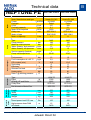
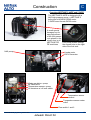
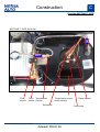
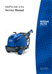
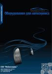
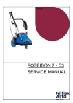
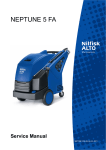
NEPTUNE PE/DE
Service Manual
NEPTUNE PE-DE_en_Ver.1.0_October 2010
Jetwash Direct ltd
A. Safety instructions
B. Technical data
5
6- 9
C. Construction
10 -17
D. Function
18 -37
E. Troubleshooting
38 -41
F. Service / Repair
42-62
G. Adjustment / Test
63-71
H. Wiring diagrams
72-92
Jetwash Direct ltd
Index
A. Safety instructions ................................................... 5
B. Technical data........................................................... 6
C. Constrution
-Overview Unit: .......................................................... 13
D. Function
-Electrical.................................................................... 18
-Funktion PCB ............................................................ 24
-Pumps ....................................................................... 28
-By-pass valves & Unloader………………………….... 31
-Flow Switch…………………………………………… .. 35
-Heat Exchanger......................................................... 36
E. Troubleshooting
-Table ......................................................................... 38
F. Service / Repair
-NA5 Pump ................................................................. 42
-C3 Pump ................................................................... 48
-NP5 Pump ................................................................. 54
-Heat Exchanger ........................................................ 59
-Electrodes ................................................................. 61
-Maintenance………… ............................................... 62
G. Adjustment / Test
-NA5 ........................................................................... 63
-C3.............................................................................. 66
-NP5 ........................................................................... 67
-Heat Exchanger......................................................... 69
H. Wiring diagrams
- ................................................................................. 72
NEPTUNE PE-DE_en_Ver.1.0_October 2010
Jetwash Direct ltd
3
Preface
This service manual contains detailed description of the main repair work on the Hot
Water High Pressure Washer, NEPTUNE PE—DE.
If operating errors are evident, refer the customer to the operating instructions.
A fault in the cleaner can have several causes as described in the section on troubleshooting.
Refer to the illustrated spare parts lists during repairs. They show the assembly position and the sequence in which the individual components should be assembled.
Repair manuals and TSB (Technical Service Bulletin) sheets should be available at
the site where repairs are carried out.
It is not permitted to give them to third parties.
Use original Nilfisk-ALTO spare parts only.
NEPTUNE PE-DE_en_Ver.1.0_October 2010
Jetwash Direct ltd
4
Safety instructions
A
The high-pressure cleaner
should only be used by authorized persons who have been
instructed in its use.
For your own safety
Although extremely easy to
operate, children should not
be allowed to use the cleaner.
Before using the cleaner, always read the operating
instructions and keep them
readily available.
Repair work should be carried
out by persons instructed and
trained in repairing this product.
NEPTUNE PE-DE_en_Ver.1.0_October 2010
Jetwash Direct ltd
5
Technical data
Motor Manufacturer and type
Power
Fuel type
CCM
Fuel tank capacity
Motor RPM, adjusted
Pulley size
Motor oil type
Motor oil capacity
Liter
Honda GX 390
11,0/3600
Petrol
389
6,1
3400
SPZ 55,4/1
SAE 15/40
1,1
bar
bar
l/min
l/min
meter
°C
NA5
188
167
12
13,5
3
35-40
NA5
198
170
13,5
15
3
35-40
12
3,9
10,5
0
92
57
68
75
10
3,9
10,5
0
92
57
81
81
t16W-75
1000
2825
SPZ 63/1
SPZ 670
t16W-75
1000
2825
SPZ 60/1
SPZ 670
Pump
Heat exchanger
Cm3
Liter
RPM
mm
Type
Pump pressure
Machine outlet pressure
Water Quantity, high pressure
Water Quantity, low pressure
Suction capacity (feeded)
Pump inlet temperature
Fuel pressure
Fuel consumption dt = 45 °C
CO2 content (min.)
Soot rating
Efficiency
Onboard fuel tank
Heater rating
Delta T @ working pressure
Type
Effect
RPM @ HP and Boiler
PUlley Size
Belt dimension Motor/Gen.
NEPTUNE 5-46PE NEPTUNE 5-54PE
Honda GX 340
9,5/3600
Petrol
337
6,1
3550
SPZ 55,4/1
SAE 15/40
1,1
HK/RPM
Generator
Motor
NEPTUNE PE
B
bar
kg/h
%
%
Litre
kW
ºC
Dimensions
and weight
Length
Width
Height
Weight
mm
mm
mm
kg
970
780
1000
208
970
780
1000
208
Miscella
neous
W
RPM
Sound power level CE, Lwa
High-pressure hose DN8
HP nozzle
Db
m
105
15
0400
105
15
0450
NEPTUNE PE-DE_en_Ver.1.0_October 2010
Jetwash Direct ltd
6
Technical data
Motor Manufacturer and type
Power
Fuel type
CCM
Fuel tank capacity
Motor RPM, adjusted
Pulley size
Motor oil type
Motor oil capacity
Fuel pressure
Fuel consumption dt = 45°C
CO2 content (min.)
Soot rating
Efficiency
Onboard fuel tank
Heater rating
Delta T @ working pressure
Honda GX 630
20,8/3600
Petrol
670
20 (External tank)
3340
SPZ 80/4
SAE 15/40
1,9
bar
bar
l/min
l/min
meter
°C
C3
202
192
16
18
3
35-40
NP5
210
195
20
21,5
5
35-40
11
4,6
10,5
0
92
57
87
70
12
5,75
10,5
0-1
92
57
111
70
t16W-75
1000
2825
SPZ 63/1
SPZ 670
t16W-75
1000
2825
SPZ 60/1
SPZ 670
Cm3
Liter
RPM
mm
bar
kg/h
%
%
Litre
kW
ºC
W
RPM
Dimensions
and weight
Type
Effect
RPM @ HP and Boiler
PUlley Size
Belt dimension Motor/Gen.
Liter
Honda GX 390
11,0/3600
Petrol
389
6,1
3550
SPZ 55,4/1
SAE 15/40
1,1
HK/RPM
Type
Pump pressure
Machine outlet pressure
Water Quantity, high pressure
Water Quantity, low pressure
Suction capacity (feeded)
Pump inlet temperature
NEPTUNE 7-61PE NEPTUNE 5-85PE
Length
Width
Height
Weight
mm
mm
mm
kg
970
780
1000
210
1130
910
1050
260
Miscella
neous
Generator
Heat exchanger
Pump
Motor
NEPTUNE PE
B
Sound power level CE,Lwa
High-pressure hose DN8
HP nozzle
Db
m
105
15
0500
106
15
0650
NEPTUNE PE-DE_en_Ver.1.0_October 2010
Jetwash Direct ltd
7
Technical data
Motor Manufacturer and type
Power
Fuel type
CCM
Fuel tank capacity
Motor RPM, adjusted
Pulley size
Motor oil type
Motor oil capacity
Fuel pressure
Fuel consumption dt = 45°C
CO2 content (min.)
Soot rating
Efficiency
Onboard fuel tank
Heater rating
Delta T @ working pressure
Ruggerini
16/3500
Diesel
20 (External tank)
3500
SAE 15/40
1,8
bar
bar
l/min
l/min
meter
°C
NP5
185
176
13,5
15
3
35-40
C3
185
170
18,7
20
5
35-40
10
3,9
10,5
0
92
57
81
81
12
4,85
10,5
0-1
92
57
111
76
t16W-75
1000
2825
SPZ 63/1
SPZ 670
t16W-75
1000
2825
SPZ 60/1
SPZ 670
Cm3
Liter
RPM
mm
bar
kg/h
%
%
Litre
kW
ºC
W
RPM
Dimensions
and weight
Type
Effect
RPM @ HP and Boiler
PUlley Size
Belt dimension Motor/Gen.
Liter
Yanmar
10/3600
Diesel
406
5,5
3530
SPZ 80/3
SAE 15/40
1,65
HK/RPM
Type
Pump pressure
Machine outlet pressure
Water Quantity, high pressure
Water Quantity, low pressure
Suction capacity (feeded)
Pump inlet temperature
NEPTUNE 5-51DE NEPTUNE 7-66DE
Length
Width
Height
Weight
mm
mm
mm
kg
970
780
1000
220
1130
910
1050
315
Miscella
neous
Generator
Heat exchanger
Pump
Motor
NEPTUNE PE
B
Sound power level CE, Lwa
High-pressure hose DN8
HP nozzle
Db
m
110
15
0450
112
15
0650
NEPTUNE PE-DE_en_Ver.1.0_October 2010
Jetwash Direct ltd
8
Technical data
Motor Manufacturer and type
Power
Fuel type
CCM
Fuel tank capacity
Motor RPM, adjusted
Pulley size
Motor oil type
Motor oil capacity
Mitsubishi
HK/RPM
16/1630
Diesel
Cm3
1318
Liter
20 (External tank)
RPM
1600
mm
SAE 15/40
Liter
4,2
Type
Pump pressure
Machine outlet pressure
Water Quantity, high pressure
Water Quantity, low pressure
Suction capacity (feeded)
Pump inlet temperature
Fuel pressure
Fuel consumption dt = 45°C
CO2 content (min.)
Soot rating
Efficiency
Onboard fuel tank
Heater rating
Delta T @ working pressure
bar
bar
l/min
l/min
meter
°C
bar
kg/h
%
%
Litre
kW
ºC
W
RPM
C3
200
185
19,5
21,5
5
35-40
12
5
10,5
0-1
92
57
111
76
t16W-75
1000
2825
SPZ 63/1
SPZ 670
Dimensions
and weight
Type
Effect
RPM @ HP and Boiler
PUlley Size
Belt dimension Motor/Gen.
NEPTUNE 7-72DE
Length
Width
Height
Weight
mm
mm
mm
kg
1130
910
1050
510
Miscella
neous
Genarator
Heat exchanger
Pump
Motor
NEPTUNE PE
Sound power level CE, Lwa
High-pressure hose DN10
HP nozzle
dB
m
99
15
0640
NEPTUNE PE-DE_en_Ver.1.0_October 2010
B
Jetwash Direct ltd
9
Construction
C
Overview NEPTUNE 5-46PE and 5-54PE
The NEPTUNE 5-46PE is designed with a
NA5 high pressure pump, a NEPTUNE 5
boiler and a HONDA GX340 motor.
5-54PE has a Honda GX390 motor
A small special
hexagon key for
easy adjustment
of the fuel pressure is placed in the
electric box in all
NEPTUNE PE/
Fuel pump access through
DE machines
the square hole on the right
side of the fuel tank.
NA5 pump
Honda motor
230V Generator
Water regulation—pump
By-Pass valve
Temperature sensor—pump
Oil container w/ oil level switch
Temperature sensor
exhaust
Temperature sensor water
outlet
Flow switch 1 and 2
NEPTUNE PE-DE_en_Ver.1.0_October 2010
Jetwash Direct ltd
10
Construction
C
Overview NEPTUNE 7-61PE
The NEPTUNE 7-,61PE is designed with
a C3 high pressure pump, a Honda
GX390 motor with 13 HP, control system
same as on the NEPTUNE 3, and a
NEPTUNE 5 boiler
NEPTUNE 7-61PE, front side
A small special
hexagon key for
easy adjustment
of the fuel pressure is placed in the
electric box in all Fuel pump access
through the square
NEPTUNE PE/
hole in the fuel tank.
DE machines
Water outlet
Honda Motor
C3 pump
Water Break tank, OPTIONAL
Water regulator
Anti Scale container, OPTIONAL
Wheels, OPTIONAL
NEPTUNE 7-61PE, front side
NEPTUNE PE-DE_en_Ver.1.0_October 2010
Jetwash Direct ltd
11
Construction
C
Overview NEPTUNE 7-61PE
NEPTUNE 7-61PE, boiler top
IN
OUT
Flowswitch
Flow- Temperature
switch Sensor
Temperature sensor,
boiler exhaust
Electrodes
NEPTUNE PE-DE_en_Ver.1.0_October 2010
Jetwash Direct ltd
Flame sensor
Fuel nozzle
12
Construction
C
Overview NEPTUNE 7-61PE
NEPTUNE 7-61PE, backside
Generator, 230V
NEPTUNE PE-DE_en_Ver.1.0_October 2010
Charging relay
Top cover
Jetwash Direct ltd
13
Construction
C
Overview NEPTUNE 5-85PE
The NEPTUNE 5-85PE is designed with a NP5
high pressure pump, a Honda GX630 motor with
20 HP, control system same as on the NEPTUNE
3, and a NEPTUNE 7 boiler
Fuel pump access through
the square hole on the right
side of the fuel tank.
A small special
hexagon key for
easy adjustment
of the fuel pressure is placed in the
electric box in all
NEPTUNE PE/
DE machines
Honda motor
NP5 pump
Temperature
sensor—pump
Safety valve.
Oil glass Water
w/level inlet
switch
Unloader
(This safety valve
is used only on 585PE and 551DE, becasue
the unloader does
not have a safety
valve).
Generator
Battery—12V
NEPTUNE PE-DE_en_Ver.1.0_October 2010
Jetwash Direct ltd
14
Construction
C
Overview NEPTUNE 5-51DE
The NEPTUNE 5-51DE is designed with
a NP5 high pressure pump, a Yanmar
motor with 10 HP, control system same
as on the NEPTUNE 3, and a NEPTUNE
5 boiler.
Fuel pump access
through the square hole
on the right side of the
fuel tank.
Battery 12V Generator
230V
A small special
hexagon key for
easy adjustment
of the fuel pressure is placed in the
electric box in all
NEPTUNE PE/
DE machines
Yanmar
motor
Temperature sensor
exhaust
Safety valve (only on 5-51DE & 5-85DE)
Temperature sensor water
outlet
Flow switch 1 and 2
Unloader & water regulator
NP5 pump
Oil container w/level switch
Thermal dump valve
NEPTUNE PE-DE_en_Ver.1.0_October 2010
Jetwash Direct ltd
15
Construction
C
Overview NEPTUNE 7-66DE
The NEPTUNE 7-66DE is designed with a
C3 high pressure pump, a Ruggerini motor
with 16 HP, control system same as on the
NEPTUNE 3, and a NEPTUNE 7 boiler.
A small special
hexagon key for
easy adjustment
of the fuel pressure is placed in the
electric box in all
Fuel pump access
through the square hole NEPTUNE PE/
on the right side of the DE machines
fuel tank.
Rugerinni motor
Oil container w/level sensor
Gera box between motor and pump
C3 pump
By-pass valve W/water regulator
Temperature sensor—pump
Temperature sensor
exhaust
Temperature sensor water
outlet
Flow switch 1 and 2
NEPTUNE PE-DE_en_Ver.1.0_October 2010
Jetwash Direct ltd
16
Construction
C
Overview NEPTUNE 7-72DE
The NEPTUNE 7-72DE is designed
with a C3 high pressure pump, a Mitsubishi motor with 15 HP, control system
same as on the NEPTUNE 3, and a
NEPTUNE 7 boiler.
Fuel pump access
through the square hole
on the right side of the
fuel tank.
A small special
hexagon key for
easy adjustment
of the fuel pressure is placed in the
electric box in all
NEPTUNE PE/
DE machines
Mitsubishi motor
Oil container w/level
sensor
Temperature
By-pass valve C3 pump
sensor—pump w/ water regulator
Temperature sensor
exhaust
Temperature sensor water
outlet
Flow switch 1 and 2
NEPTUNE PE-DE_en_Ver.1.0_October 2010
Jetwash Direct ltd
17
Function
D
Functional desription of NEPTUNE 5-46PE, 5-54PE and 7-61PE
Start the motor by shortly turning the key (5) into the start position. When you let go the key, the key
moves back to the ”ON” position.
When the key is turned to the start position, the start relay (13) is pulled, and the start motor is turning the motor.
In the ”ON” position the battery is continuously charged by the AC generator (9) through the rectifier
(2).
With the key in “ON” position, the hour counter will count, no matter if the motor is running or not.
NEPTUNE PE-DE_en_Ver.1.0_October 2010
Jetwash Direct ltd
18
Function
D
Functional desription of NEPTUNE 5-46PE, 5-54PE and 7-61PE
Circuit board (A2) is monitoring the thermostat on the high pressure pump (15), the motor
oil switch (8) and the oil level switch in the high pressure pump.
If the thermostat on the pump or the motor oil switch is closing (failure) is respectively input 9 and input 8 connected to ground, which causes the LED to light, and at the same
time output 15 is connected to ground.
If the oil level switch closes (failure) input 5 is connected to ground, output 15 is also connected to ground, which pulls the relay (6) and the motor stops. Also the LED for low oil
level will light up.
On this model it is important that the jumper on A2 (2A) is NOT mounted.
NEPTUNE PE-DE_en_Ver.1.0_October 2010
Jetwash Direct ltd
19
Function
D
Functional desription of NEPTUNE 5-51DE
Start the motor by shortly turning the key (5) into the start position. When you let go the key, the key
moves back to the ”ON” position.
When the key is turned to the start position, the start relay (13) is pulled, and the start motor is turning the motor.
Circuit board (A2) is monitoring the thermostat (E) on the high pressure pump, the motor oil switch
(D) and the oil level switch in the high pressure pump.
If the thermostat (E) on the pump is closing (failure) is input 8 connected to ground, which causes
the LED to light, and at the same time output 15 is connected to
ground.?????????????????????
If the charging generator (I) is not charging, wire (Y) in the regulator (O) is getting 12V and also the
input 7 on A2 is then getting 12V, which makes the charging light lighten.
On this model it is important that the jumper on A2 (2A) is NOT mounted, for the charging system to
work properly.
NEPTUNE PE-DE_en_Ver.1.0_October 2010
Jetwash Direct ltd
20
Function
D
Functional desription of NEPTUNE 7-66DE
When the key (S1) is turned to start, the start relay is pulled and the motor starts. Then let go the
key, and it moves back to the ”ON” position.
The motor oil pressure switch (B10) is a normally closed switch. In closed position (motor not running) the switch is connected to ground. When the motor starts and the RPM increases the motor oil
pressure increases the switch opens and there is no connection to ground anymore. When no connection to ground there is no ground on output 15, which means the motor runs.
If output 15 is connected to ground 5 sec. after the key is turned back to “ON” position, contactor K3
is pulled, and the fuel pump is disconnected for 9 sec. (done by TIM 2—Timer for motor stop) —
motor stops.
If there is a failure on sensor B5, B 10 or B11, and by that output 15 is connected to ground, the fuel
pump will be disconnected in 9 sec., and the motor will stop.
If the 12V charging is not functioning input 6 on A2 will be connected to ground.
IMPORTANT: JUMPER ON A2 MUST BE MOUNTED
NEPTUNE PE-DE_en_Ver.1.0_October 2010
Jetwash Direct ltd
21
Function
D
Functional desription of NEPTUNE 7-72DE
When the key (S1) is turned to the ”ON” position, the glow timer (Tim1), and the glow relay (K3) is
activated, and the glow plugs (R1) are heating, and also the glow lamp on A2 is lightening. After a
short while the timer runs out and the glow relay opens.
Now the key can be turned to the start position, and the starter coil (Y2—red wire), together with the
holding coil (Y2—white wire) is pulled and runs the starter motor, and the motor will start.
Now release the key, so it goes back to the “ON” position, the starter coil (Y2—red wire) is no longer
pulled, but the holding coil (Y2—white wire) is kept hold through the contactor (K3).
If there is a failure on B5 (oil level switch pump oil), B10 (Motor oil switch), B11 (thermo switch motor) or B12 (thermo switch high pressure pump), output 15 on A2 is connected to ground, contactor
K3 opens and the holding coil Y2 opens and the motor stops.
It is important that the jumper is mounted on the circuit board (A2). When jumper mounted there is
12VDC on output 7 on A2. Output 7 is connected to connection “R” on the generator. The generator
(G1) can only give output, if there is 12VDC present on connection “R”. If the generator is “worn/
defect” the DC voltage on connection “L” drops down to 0 VDC, and input 6 on A2 in then connected
to ground, and the charging LED will light up.
NEPTUNE PE-DE_en_Ver.1.0_October 2010
Jetwash Direct ltd
22
Function
D
Functional desription of NEPTUNE 5-85PE
If there is a failure on B5 (oil level switch pump oil), B10 (motor oil switch) or B12 (thermo switch
high pressure pump) is output 15 on A2 connected to ground. At the same time input “F” on the
Honda motor is connected to ground, and the Honda motor will stop.
IMPORTANT: JUMPER ON A2 MUST BE MOUNTED
NEPTUNE PE-DE_en_Ver.1.0_October 2010
Jetwash Direct ltd
23
Function
D
Functional desription of Circuit Board, A1
The circuit board used in all NEPTNE PE/DE machines is the same as used in NEPTUNE 3.
The only difference is the following bridges which are mounted on the circuit board in the NEPTUNE
PE/DE machines.
X4,5 to X5,6—oil level switch high pressure pump. Oil level switch is moved to circuit board A2
X4,1 to X4,2—Anti-stone
X3,5 to X3,6—Thermal switch in high pressure pump motor.
NEPTUNE PE-DE_en_Ver.1.0_October 2010
Jetwash Direct ltd
24
Function
D
Functional desription of Circuit Board, A1
Control Circuit Board (A1) is functioning the same way in all the NEPTUNE PE/DE models. The
power supply to A1 is supplied by the 230V generator G2, which is driven by the motor. This means
that the motor must be running—and running at full RPM—before the A1 is working. In cold water
mode the S1 main switch can be in position ON or OFF. If S1 is turned to the temperature area (red)
the hot water mode is activated.
When S1 is turned to ON power is supplied through the fuse F1 to the microprocessor. The microprocessor is starting up, and the 5 status LED’s is lightening up for 1 sec. If there is a failure during
start up, the control circuit board goes into failure mode.
If the S1 main switch is turned to “hot water mode”, and the spay gun is open, and desired temperature set at S1, B1 temperature sensor is measuring lower temperature that the set point at S1, and
B9 fuel level sensor is measuring fuel in the tank, and B2 flow switch, and B4 flow switch is registering water flow, the burner motor M2 is started, and the ignition transformer T2 is started over the
burner relay K3. A high voltage spark is generated between the electrodes in the burner.
The burner motor M2 is driving the burner fan, which is blowing pre-heated air into the boiler. The
self-sucking fuel pump is pumping fuel pressure up to the fuel solenoid valve Y1. When the burner
motor/fan has been running in 1 sec., the fuel solenoid valve Y1 opens, and the fuel is pumped under pressure to the fuel nozzle. The atomized fuel is leaving the fuel nozzle and is ignited.
NEPTUNE PE-DE_en_Ver.1.0_October 2010
Jetwash Direct ltd
25
Function
D
Functional desription of Circuit Board, A1—Continued
The flame sensor B7 is controlling if the fuel is ignited, and if it is (the flame sensor can see the
flame) it “allows” the burner to burn.
If the flame sensor don’t see the flame after 4 sec. (when S1 is in hot water mode), the fuel solenoid
valve will close, and the burner will be stopped.
If the display is flashing in the LED’s, it can be due to too low RPM on the motor.
If the LED’s are flashing, it means that the voltage is too low to maintain the circuit board.
The flashing LED’s means that the display is “re-starting” all the time.
NEPTUNE PE-DE_en_Ver.1.0_October 2010
Jetwash Direct ltd
26
D
Function
Functional desription of Circuit Board, A1—Continued
Circuit Board A2 (A1)
Circuit board (A2) has LED’s for
the motor, e.g. water temperature,
motor oil level etc.
Control Circuit Board A1
Control Circuit Board:
Pos. 1: The heating and ON/OFF switch (S1)
Pos. 2: Heating Relay (K2)
Pos. 3: LED’s
Pos. 4: Fuse—Self-resetting ”Pico fuse”
Pos. 5: Fuse
Pos. 6: Fuse
On the above picture is the correct setting of the
circuit board.
Arrow 1
Setting is WITHOUT JUMPER = By-pass time
active
Arrow 2:
Setting is JUMPER MOUNTED ON PIN 2 AND 3
= Flame Sensor active.
NEPTUNE PE-DE_en_Ver.1.0_October 2010
Jetwash Direct ltd
27
D
Function
NEPTUNE PE/DE—NP5 PUMP
The 3piston radial pump NP5 is used in the NEPTUNE 5-85PE and 5-51DE
OUT
Cam shaft
OIL
Pressure valve
Shaft
IN
Suction valve
The three pistons are driven by the motor via a belt drive. The cam shaft transforms the
rotation power into the pistons reciprocating movements.
The movement and the diameter of the pistons decide the water volume which can be
sucked into the suction valves and pressed out through the pressure valves.
NEPTUNE PE-DE_en_Ver.1.0_October 2010
Jetwash Direct ltd
28
D
Function
NEPTUNE PE/DE—NA5 PUMP
The 3piston NA5 pump is used in the NEPTUNE 5-46PE and 5-54PE
Honda motor and D-bearing cover
Pistons, cylinder block,cylinder head
and sealings
Water inlet
By-pass valve with water regulator
The NA5 pump is connected to the Honda motor with a direct drive.
By-pass valve function is described later in this service manual.
NEPTUNE PE-DE_en_Ver.1.0_October 2010
Jetwash Direct ltd
29
D
Function
NEPTUNE PE/DE—C3 PUMP
The 4 piston C3 pump is used in the NEPTUNE 7-61PE, 7-66DE and 7-72DE
The wobble disc is mounted directly on the motor shaft.
Water is sucked through the suction valves and out through the pressure valves and the piston in the by-pass valve. The piston has two small holes where the water is running through
in order to create a pressure drop, which make sure the valve cone is closed during operation.
When water flow is interrupted, the pressure rises until the safety valve opens. Because of
the achieved pressure drop, the valve cone is pressed to open so the water re-circulates at a
pressure < 10 bar.
Water quantity is regulated by a handle in the end of the by-pass valve. When turning the
handle clockwise, the by-pass valve cone will be forced open, so some of the water is recirculating in the pump.
NEPTUNE PE-DE_en_Ver.1.0_October 2010
Jetwash Direct ltd
30
D
Function
By-Pass valve function NEPTUNE 5-46PE and 5-54PE
G
F
H
E
D
K
I
J
C
B
A
Working pressure
Machine is started and the gun ”J” with correct lance/nozzle is open Machine runs in working pressure ”K”:
The water is pressed from the pump outlet ”A” into the by-pass housing ”C”.
The water runs through the bottom of by-pass housing ”C” and directely to the outlet ”I”.
Due to the water pressure the by-pass piston ”B” is pressed up and the seat ”E” is closed.
G
F
H
E
D
I
J
K
C
B
A
By-pass pressure
Machine is started and the gun is closed - By-pass pressure:
When the gun ”J” closes, the pressure inside the by-pass housing equalizes and the by-pass
piston ”B” is pressed down by the tension of it’s spring. The seat ”E” in the top of by-pass piston
opens. The water runs from the pump outlet ”A” into the by-pass housing ”C”. Due to the closed
gun ”J” and the opening in the by-pass seat ”E”, the water runs back into the suction side of the
pump through the valve ”D”.
NEPTUNE PE-DE_en_Ver.1.0_October 2010
Jetwash Direct ltd
31
D
Function
By-Pass valve function NEPTUNE 5-46PE and 5-54PE
C
B
A
By-pass pressure
The by-pass pressure is determined of the spring tension in valve ”A”.
The tension is fixed and will bring out a by-pass pressure in about 30 - 35 bar.
Valve ”A” also secures the self suction ability.
The cut off pressure when the gun is released, is determined of the adjustment screw ”B”.
When the screw is tightened the cut off pressure will rice and by loosening it the pressure will
fall.
The safety valve ”C” has no function under normal circumstances. The pressure of the safety
valve is set to about 25 - 30 bar above the cut off pressure.
The safety valve will open if the by-pass valve is stocked and lead water to the suction side of
the pump.
G
F
H
E
D
I
K
C
B
A
Water reduction
When the water regulation ”G” is turned counter clock wise, the seat ”H” opens and the
water runs both to the outlet of the by-pass housing and in by-pass to the suction side of
the pump.
The pressure ”K” will fall depending of the size of the opening in seat ”H”.
NEPTUNE PE-DE_en_Ver.1.0_October 2010
Jetwash Direct ltd
32
Function
D
By-Pass valve function NEPTUNE 7-61PE, 7-66DE, 7-72DE
Operation:
The water from the pump is lead into
the chamber ”A” in the by-pass valve.
From here the water passes through
the holes “B” in the by-pass valve piston “C” and out to the high pressure
nozzle. When water is pressed
through holes in the piston “C”, there is
a pressure drop over the piston (this
means the pressure is higher on one
side of the piston). This will keep the
valve cone “D” closed against its seat
“E”, because the piston “C” is fixed to
the valve cone.
NEPTUNE PE-DE_en_Ver.1.0_October 2010
By-Pass:
When the water consumption stops
(spray handle is released/closed), the
pressure drop over piston “C” disappears, the pressure in the by-pass
valve increases briefly until the safety
valve “F” opens. The safety valve just
opens briefly, and closes again. The
safety valve opens when the pump
pressure overcomes the tension of the
spring in the safety valve. (The safety
valve is adjusted to open 25-30 bar
above normal working pressure). Now
the valve cone “D” lift from its seat “E”,
and water runs in by-pass.
Jetwash Direct ltd
33
Function
D
Unloader valve function NEPTUNE 5-85Pe AND 5-51DE
Unloader mounted on pump
Unloader function:
On the assumption that the black handle
(adjustment handle) on the unloader is turned all
the way to max. pressure (clockwise).
When the pump is running the unloader piston (2)
is pressed down it its seat (1), and all the water
volume is going through the gun and out to the
high pressure nozzle.
When the gun is released (no water flow out), the
pressure in the unloader will rise, and the increased pressure will overcome the adjusted tension of the unloader spring (6), and the unloader
piston (2) will be lifted up from its seat.
Water will now return through the seat (1) to the
suction side of the pump (by-pass) mode.
Unloader disassembled
NEPTUNE PE-DE_en_Ver.1.0_October 2010
Jetwash Direct ltd
34
D
Function
Flow switch function NEPTUNE PE
Flow switch
Plug with Shaft
Water supply connected to the machine.
Water from the pump is pressed through the high pressure hose to the first flow switch.
When water is entering the first flow switch, the piston with magnet is pressed to the top of the flow
switch housing, and the reed switch is making contact and closing the circuit.
(Reed switch is a NO contact)
Water is now pressed through the second flow switch, the piston with magnet is pressed to the far
end of the housing, and the reed switch is making contact and closing the circuit.
When the spray handle is released and the water flow stops, the flow switch pistons will move away
from the reed switches, and the will brake off the circuit and the burner will stop.
When the water flow stops, the piston in the first flow switch will fall down and be stopped by the
plug with the shaft. The plug with shaft is installed to reduce the movement of the piston.
The signals from the two flow switches must come simultaneously. (MAX. difference between the
two signals are 4 seconds)
The signals from the flow switches are controlling the fuel pump solenoid valve. This to make sure
that the burner is not starting if there is no flow of water through the heating coil.
NEPTUNE PE-DE_en_Ver.1.0_October 2010
Jetwash Direct ltd
35
D
Function
Heat exchanger NEPTUNE PE
Heat exchanger (schematic)
Fig. D.19:
1) Burner fan
2) Baffle plate
3) Fuel nozzle
4) Heating coil
5) Fuel pump
6) Fuel filter
7) Solenoid valve
8) Nozzle stock
9) Fuel return line
10) Ignition transformer
11) Ignition electrodes
12) Flame probe
13) Flue
14) Flame sheath
15) Flame funnel
16) Insulation
17) Water inlet
18) Water outlet
NEPTUNE PE-DE_en_Ver.1.0_October 2010
The heat exchanger is the functional link between the heating subsystem and the water subsystem.
In "Hot water" mode the burner fan
(1) draws in air and conducts it laterally into the heat exchanger
where it is routed upwards between
the two jackets to the baffle plate
(2). This preheats the air before it
mixes with the fuel spray from the
fuel nozzle (3).
Cold water is fed to the inner circuit
in which the temperature is highest.
This reduces in as much as possible any condensation on the surface of the heating coil (4).
At the same time fuel is drawn in
from the fuel tank by the fuel pump
(5) through the filter (6). The fuel is
conducted by the solenoid valve (7)
to the nozzle stock (8) with the fuel
nozzle (3). If no combustion is
needed, the fuel goes back to the
tank on the return line (9).
The ignition transformer (10) activated in "Hot water" mode generates ignition sparks across the electrodes (11) to ignite the fuel spray.
This process is monitored by the
flame sensor (12).
In normal operation the hot exhaust
flows downwards and upwards between the piping of the heating coil
(4) thus warming the water in the
system.
The exhaust exits through the flue
(13).
Jetwash Direct ltd
36
Function
D
Safety Thermal Temperature Sensor in boiler exhaust
Located in the heat exchanger outlet (flue) is a temperature-dependent resistor (Pt 100) functioning as a temperature sensor.
If the temperature in the heat exchanger outlet (actual
temperature) exceeds the temperature set-point, the solenoid valve Y1 closes to interrupt the fuel feed. The
temperature sensor is only activated in "Hot water"
mode.
The safety thermal release mounted on the heat exchanger water inlet, is an absolute safety
element on the heat exchanger.
If a fault is present, e.g. all control and safety devices fails, and hot water flows at high pressure from the heat exchanger back through the safety valve into the high pressure pump, the
thermal release responds and shuts down the entire machine through the control circuit. Before restarting, the machine must cool down, the fault causing the heated water to flow in the
wrong direction must be corrected, and a new thermal release fitted.
The flame sensor is a light-sensitive phototransistor.
The flame sensor checks for the presence of a flame.
NEPTUNE PE-DE_en_Ver.1.0_October 2010
Jetwash Direct ltd
37
Troubleshooting
Fault
Cause
E
Remedy
⇒
Machine ready to opeate.
All LEDs flash once before the motor is turned
on.
⇒
Fuel level is low.
•
Refill fuel. "Cold water"
mode is possible.
⇒
Alto Anti Stone level is •
low.
Refill Alto Anti Stone.
"Hot water" and "Cold
water" mode is possible.
Red LED illuminates.
⇒
Pump oil level is low.
•
Refill pump oil (Chapter
F.1.3). The burner and
motor are cut out. The
green LED extinguishes.
Red LED flashes.
⇒
Service interval: service •
due in 20 hours.
Service the machine.
"Hot water" and "Cold
water" mode is possible.
Red LED illuminates.
⇒
Service interval elapsed.
•
Service the machine.
"Hot water" and "Cold
water" mode is possible.
Green LED illuminates.
Yellow LED illuminates.
Yellow LED flashes.
NEPTUNE PE-DE_en_Ver.1.0_October 2010
Jetwash Direct ltd
38
Troubleshooting
Fault
Green LED flashes.
Cause
Remedy
⇒
Flow sensor fault.
•
⇒
Water tap closed or water flow inadequate.
Detergent tank empty.
•
Pressure rate control or
Vario Press set for too
small amount of water.
Machine scaled up.
•
⇒
Leakage or impermissible operating status
through brief operation.
•
⇒
⇒
Spray pistol leaking.
HP hose, HP coupling or
pipe leaking.
Detergent tank empty.
Filter clogged in water
intake.
HP pump sucking in air.
⇒
⇒
⇒
Green LED and
red LED flash simultaneously.
⇒
⇒
⇒
NEPTUNE PE-DE_en_Ver.1.0_October 2010
E
•
•
•
•
•
•
•
See Chapter F.3.3,
F.3.5 and G.3.4."Cold
water" mode is possible.
Requirements in Chapter B.
Refill detergent or set
the SDR valve to "0".
Set the pressure rate
control or Vario Press
for a higher water flow.
Descale the machine.
The machine cuts out
after being briefly operated three times. Reset:
set the main switch to
"Off". Operate the pistol
for > 3 s.
Check the spray pistol.
Tighten the screws, replace the HP hose or
pipe.
Refill detergent.
Clean the filter
Correct leaking points.
Jetwash Direct ltd
39
Troubleshooting
Fault
Cause
⇒
Green LED and
red LED flash alternately
Motor/machine overheated (MT has triggered).
Remedy
•
•
Set the main switch to
"Off". Allow the machine
to cool.
Work without an extension cable or use an extension cable with a larger cross-section.
•
Possibly a phase failure:
have the electrical connection checked.
Thermal release B3 has
tripped.
•
Correct the cause of the
fault (Chapter D.2.3.5)
and replace the thermal
release (Chapter F.7.4).
⇒
24 Vac fine-wire fuse F2
has blown.
•
Correct the cause of the
fault and replace the
fine-wire fuse (Chapter
F.8.1).
⇒
Fault in fuel or ignition
system, burner fault.
•
See Chapter F.2.6 and
F.7. "Cold water" mode
is possible.
⇒
Flame probe (option)
sooted up.
•
If this option is fitted, remove it and clean it.
⇒
⇒
Green LED
flashes slowly &
red LED flashes
fast
E
NEPTUNE PE-DE_en_Ver.1.0_October 2010
Jetwash Direct ltd
40
Troubleshooting
Fault
Green LED does
not illuminate.
Pressure too low.
Machine runs jerkily.
Cause
⇒
E
Remedy
No power to microproc- •
essor.
Make sure the machine
is plugged in.
•
Operate main switch S1.
•
Check the primary and
secondary voltage (8
Vac) on transformer T1.
•
Pico fuse F1 has blown
(self-resetting). Wait until F1 is reset or, if the
fault persists, replace
electronic controller A1
(Chapter F.8.1).
⇒
HP nozzle worn.
•
Replace the HP nozzle.
⇒
Pressure rate control or
Vario Press set for too
low a pressure.
•
Turn the pressure rate
control on the unloader
valve in the direction
"+", or set the Vario
Press rotary knob
(accessory) on the pistol
for a larger amount of
water.
⇒
Flexo Power nozzle •
open.
HP pump taking air in •
from empty detergent
tank
Close the Flexo Power
nozzle.
Close the detergent dosing valve. Take the
spray pipe off the spray
pistol. Operate the spray
pistol and let the machine run until the air is
expelled from the system and the pump works
smoothly.
⇒
NEPTUNE PE-DE_en_Ver.1.0_October 2010
Jetwash Direct ltd
41
Service / Repair
F
NA5 Pump
NEPTUNE PE-DE_en_Ver.1.0_October 2010
Jetwash Direct ltd
42
Service / Repair
F
NA5 Pump
Valves
Fig.F.13: Valve housing
Fig.F.14: Thrust collar
•
•
•
Dismount the valve housing from the
cylinder block by the three M12 bolts.
Be aware of the o-rings and valve parts.
•
Be carefull not to damage the surface
inside when dismounting the thrust collar.
Inspect the thrust collar for damages
before mounting.
Fig.F.15: Valve housing
Fig.F.16: Valve housing
•
•
Carefully tip out the sleeves with an
adequate screwdriver and replace them. Be
careful not to scratch the surface.
•
NEPTUNE PE-DE_en_Ver.1.0_October 2010
Knock carefully on the back side of the
valve seat to demount it or use an 8mm
threaded pin and pull it out.
Replace with new parts.
Jetwash Direct ltd
43
Service / Repair
F
NA5 Pump
Valves
Pic. F.17: Suction valves
Pic. F.18: Pressure valves
•
•
Overview of the placement of suction valve
parts.
Overview of the placement of pressure
valve parts
Picture of piston guides
Fig.F.19: Pressure valves
Fig.F.20: Pressure valve seat
•
•
•
The pressure valves can easily be taken
out of the cylinder head.
Replace with new parts if necessary.
•
NEPTUNE PE-DE_en_Ver.1.0_October 2010
Take out the pressure valve seats with
an adequate puller or use an 8mm
threaded pin.
Replace with new parts if necessary.
Jetwash Direct ltd
44
Service / Repair
F
NA5 Pump
Cylinder Block
NEW !
Fig.F.21: Cylinder block
Fig.F.22: Oil Sleeves
•
•
Overview of the placement of the parts in
the cylinder block.
•
Take out the oil sleeves using an
adequate screwdriver.
Be careful not to damage the surface of
the cylinder block.
Oil seal and piston
Fig.F.23: Valve Kit 3~ - Exploded View
Fig.F.24: Pistons
•
•
•
To make replacement easier moisten the
sleeves with soapy water.
Mount the sleeves using a 19mm box
spanner and a fiber hammer.
NEPTUNE PE-DE_en_Ver.1.0_October 2010
•
Place sleeves, pistons and springs as
shown.
Mount the cylinder block to the D-bearing
cover by the two 6mm mounting screws.
Jetwash Direct ltd
45
Service / Repair
F
NA5 Pump
Wobble disc
Fig.F.25: Pump head
Fig.F.26: D-bearing cover and wobble disc
•
•
The cylinder head and the cylinder block
is fastend to the D-bearing cover by two
6mm mounting bolts for the cylinder
block and three 12mm bolts for the
cylinder head.
Overview of the parts inside the Dbearing cover.
Fig.F.27: Wobble disc
Fig.F.28: Wobble disc removal
•
•
The center bolt is fixing the wobble disc
to the motor shaft and ensure the rotor to
be kept in the right position in proportion
to the stator.
NEPTUNE PE-DE_en_Ver.1.0_October 2010
Demount the wobble disc screwing a 1
6mm bolt into the threads. Tighten the
bolt against the motorshaft and pull the
wobble disc out.
Jetwash Direct ltd
46
Service / Repair
F
NA5 Pump
D-bearing cover
Fig.F.29: D-bearing cover
Fig.F.30: Oil sleeve
•
•
•
The D-bearing cover is mounted to the
Motor by four 6mm bolts.
When the bearing is damaged, always
replace the complete D-bearing cover.
NEPTUNE PE-DE_en_Ver.1.0_October 2010
•
The oil sleeve in the D-bearing cover can
be demounted carefully using a
screwdriver.
Mount the oil sleeve by using an
adequate box spanner and a fiber
hammer.
Jetwash Direct ltd
47
Service / Repair
F
C3 Pump
NEPTUNE PE-DE_en_Ver.1.0_October 2010
Jetwash Direct ltd
48
Service / Repair
F
C3 Pump
Mandrel no.: 1216506
NEPTUNE PE-DE_en_Ver.1.0_October 2010
Jetwash Direct ltd
49
Service / Repair
F
C3 Pump
Ke
n
n
ey
Duct
Mounting of textile sleeves by means of tool no. 1220090. It is an
advantage if the sleeves havebeen in a water bath for 3-4 hours before
mounting them. Do not forget to blow air through the ducts.
NEPTUNE PE-DE_en_Ver.1.0_October 2010
Jetwash Direct ltd
50
Service / Repair
F
C3 Pump
Washer
O-ring
Thrust collar
Torque: 37 Nm
Oil sleeve
Secondary sleeve
Spacer ring (Crovn)
Drain off the oil. Loosen the 8 bolts gradually (because of the spring load). Special
box head no.1206762 may be used.
Mount new O-rings on studs with tool no. 1206812.
Spacer ring
Always replace
secondary sleeves when
replacing pressure
sleeves. Check that there
is a free passage from
the drain holes.
Secondary sleeve
NEPTUNE PE-DE_en_Ver.1.0_October 2010
Back-up ring
Jetwash Direct ltd
O-ring
51
Service / Repair
F
C3 Pump
Carefully tip out the oil sleeves
with an adequate screwdriver and
discard them. Be careful not to
scratch the surface.
Before mounting the new sleeves,
it will be a good idea to moisten
the sleeves with soapy water.
Mount new oil sleeves with punch
no.1220429. Carefully knock or
press them home.
Oil sleeve
LP
HP
Check the piston for wear
in the pressure area and
the area fPressure area
(rides on wobble disc)
or oil sleeves. Check the
ceramic for cracks. Remove any coating.
Pressure area,
touches
the bearing disk
Stainless steel
NEPTUNE PE-DE_en_Ver.1.0_October 2010
Ceramic
Jetwash Direct ltd
52
Service / Repair
F
C3 Pump
Dismount locking ring on the rotor shaft.
The wobble disc is easily dismounted
with puller no. 1205715 and special legs
no. 1206150/1206168. Do not forget to
remove the key before dismounting the
D-bearing cover.
Check bearing surfaces for wear. If in
doubt, replace kit complete after approx.
2000 hours.
When mounting the D-bearing cover complete,protect the U sleeve with tool no.
1206598 which is placed on the shaft, before placing the cover.
Tool : 1206598
Pittings
Check the bearing surfaces for wear. As
long as the wear is even and shiny without
pittings or grooves, the wobble disc can be
NEPTUNE PE-DE_en_Ver.1.0_October 2010
When mounting the wobble disc, lubricate
the bearings with oil. The big roller bearings
are identical. Do not forget to mount the
circlip on the rotor shaft. Refill with 1 l oil
type Castrol Alphasynt ISO 150.
Jetwash Direct ltd
53
Service / Repair
F
NP5 Pump
Valve cover & seals.
Motor
Pistons & oil seals.
Pump housing .
NEPTUNE PE-DE_en_Ver.1.0_October 2010
Jetwash Direct ltd
54
Service / Repair
F
NP5 Pump
Dismount the brass plug on the
cylinder head with a 21mm fixed spanner
and remove the valves.
Do not scratch the inside of the valve
chamber during removal!
When you replace the valves
give the o-rings an inspection
for damage before mounting.
NEPTUNE PE-DE_en_Ver.1.0_October 2010
Jetwash Direct ltd
55
Service / Repair
F
NP5 Pump
Be careful when you dismount thrust collar because you can easily damage the
surface inside. Give the thrust collar an
inspection before mounting.
When mounting the sleeves
and the spacer, remember
lubricating.
When dismounting the suction sleeves,
use a screwdriver to tip out the sleeves.
Do not reuse the sleeves.
Clean the thrust collar and lubricate before
mounting the sleeves as shown in the
ilustration.
Inspect the the thrust collar for marks,
lubricate and mount it with your fingers.
NEPTUNE PE-DE_en_Ver.1.0_October 2010
5
3
1
7
8
2
4
6
When you mount the cylinder head
tighten the bolts in the shown
sequence Use a 6mm hexagon wrench.
Jetwash Direct ltd
56
Service / Repair
F
NP5 Pump
Piston & Oil Seal
To inspect the plunger for cracks. Spray the inside of the plunger with fast evaporating cleaner
such as a brake cleansing agent. The brake cleansing agent will take a second longer to evaporate from the crack, thus making the crack visible.
Carefully inspect and replace as needed, Orings and backup rings on the plunger rod
prior to reinstalling the plungers.
Backup-ring
O-ring
Copper washer
Torque
Brass slinger plate
106 Inch pounds
8,8 ft.lbs
13NM
Oil seal
Also clean the brass slinger plates before reinstalling the plungers.
Do not re-use the copper washers!
Use one drop of medium strength thread locker on each plunger rod when reinstalling plunger
nut and torque to specifications.
Oil seals must be changed if there any signs of leaks or if they are removed.
The recommended way to remove the oil seals which are pressed into the pump body is to
sew the seal with an awl and pry down.
When installing new seals, a light coating of lubricant on the seals may ease the installation.
Make sure it is pressed in using equal pressure around the entire circumference.
NEPTUNE PE-DE_en_Ver.1.0_October 2010
Jetwash Direct ltd
57
Service / Repair
F
NP5 Pump
NP5 Unloader valve
NP5 Unloader valve
NP5 Unloader valve parts
NEPTUNE PE-DE_en_Ver.1.0_October 2010
Jetwash Direct ltd
58
Service / Repair
F
Boiler
The boiler is the heat generating part of a hot water machine. It consists of a labyrinth-constructed
tube coil, which encloses the combustion chamber. The tube coil is enclosed by a double container
with boiler jacket, bottom, and top in a sandwich construction, between which the combustion air is
routed into the combustion. An insulating material placed in the bottom of the boiler makes sure that
the inner bottom, among other things, is protected from superheating.
Flame sensor
Electrodes
Fuel nozzle
Exhaust
Water outlet
Water inlet
Top plate
Air distributor
Flame tube top part
Burner tube
Flame tube
Air inlet
Fixation spacer
Outer jacket
Inner jacket
Mounting plate
Insolation
NEPTUNE PE-DE_en_Ver.1.0_October 2010
Jetwash Direct ltd
59
Service / Repair
F
Boiler
Check the flame tube marked with X
and Y. It is important
that they are solid
and complete.
Y is a part of the coil
8 and cannot be separated.
Clean the coil.
3
4
2
4
5
6
7
X
8
Remove the outer top cover and mount the
lifting tool over the two coil ends and fix it
with the nuts. Dismount the 4 nuts
"Arrows"and hook up the crane and lift out
the coil.
Y
9
10
Burner Unit.
1.
2.
3.
4.
5.
6.
7.
Fuel solenoid
Fuel pump
Burner motor
Burner housing
Fuel filter
Fan
Fan cover
1
2
9
3
4
5
6
Clean up deposits and
change the isolation if
needed.
7
Burner fan and fuel pump.
NEPTUNE PE-DE_en_Ver.1.0_October 2010
Jetwash Direct ltd
60
Service / Repair
F
Burner Electrodes
Electrodes
Spring washer
4 mm
The electrode is adjusted from factory.
If the distance between the legs becomes greater than 4 mm, the electrode
must be changed.
The electrode 18 is self adjusting the
position on the nozzle by a spring
washer 19 under the fixing screw 20.
5 mm
6mm
4
6
7
5
11
12
9
10
13
14
17
18
19
20
21
22
The flame sensor 9 must be fixed
with 5 in the right position.
Clean the flame sensor
NEPTUNE PE-DE_en_Ver.1.0_October 2010
Jetwash Direct ltd
61
Service / Repair
F
Maintenance
Maintenance plan
Weekly
NP 5 pump only:
After the first 50
operating hours
C3 and Na5
pump every six
months or
500 operating
hours
As
required
Water filters
Oil filter
Checking the pump oil quality
Changing the pump oil
Emptying the fuel oil tank
NEPTUNE PE-DE_en_Ver.1.0_October 2010
Jetwash Direct ltd
62
Adjustment / Test
G
IMPORTANT:
NA5 pump
When torque settings are made, all parts — Pump, screws
etc. must have a temperature at 20°C.
Torque specifications
20 Nm
20 Nm
Fig.G.01: Wobble disc
Fig.G.02: Cylinder block
65 Nm
Fig.G.03: Cylinder head
25 Nm
Fig.G.04: Venting valve
10 Nm
By hand
Fig.G.06: Venting valve
Fig.G.05: By-pass housing
40 Nm
Fig.G.07: Outlet fittings
NEPTUNE PE-DE_en_Ver.1.0_October 2010
40 Nm
Fig.G.08: Water regulation
Jetwash Direct ltd
63
Adjustment / Test
G
NA5 pump
Adjustment of by-pass system.
A
Fig.G.09: Pressure gauge
Fig.G.10: Test tap
Dismount the test plug in the by-pass housing
and mount a pressure gauge instead.
Connect a test tap (A), hose and pressure
gun to the outlet of the machine.
B
Fig.G.11: Safety valve
Fig.G.12: Pressure bolt
Close the safety valve completely.
Adjust the test tap (A) and the pressure bolt
(B) so it couples 20-30 bars higher than
working pressure, when the pressure gun is
closed— CUT OFF PRESSURE. After the
cut off pressure is reached the machine
runs in by-pass untill the pressure gun is
opened.
The working pressure is stated in the technical data sheets chapter B.
NEPTUNE PE-DE_en_Ver.1.0_October 2010
Jetwash Direct ltd
64
Adjustment / Test
G
NA5 pump
Adjustment of by-pass system.
Pressure bolt
Safety valve
When adjustment is done, lock the bolt with
the counter nut.
Then let the machine run just below the cut
off pressure (working + adjustment) and adjust the safety valve out until it couples out
(go into bypass). Then you adjust the adjusting “screw” a ½ turn back and lock it
with the counter nut.
Finalize the adjustment with locking glue/
paint on both the bolt and the safety valve.
NEPTUNE PE-DE_en_Ver.1.0_October 2010
Jetwash Direct ltd
65
Adjustment / Test
G
C3 pump
Adjustment of by-pass system.
Pos. 1 Safety valve adjustment
Pos. 2 Set screw for min. Water adjustment
Pos. 3 Min. Water adjustment screw
Minimum water volume (and pressure) adjustment:
First mount test manometer with correct high pressure test nozzle.
Turn the black handle on the water regulator all the way clockwise. (Min. Water volume)
Start the motor and run at full RPM.
Test manometer must show approx. 30 bar. If this is not the case, loosen set screw (pos. 2),
and then turn the min. Water adjustment screw (pos. 3) untill you reach approx. 30 bar.
Safety valve adjustment:
First mount test manometer without test nozzle—just open outlet.
Turn the black handle on the water regulator all the way counterclockwise. (Max.. Water volume)
Start the motor and run at full RPM.
Slowly close the valve on the test manometer, and read the pressure when the safety valve
opens. (That will be the pressure just before the pressure drops)
The opening pressure for the safety valve must be 25-30 bar above normal working pressure.
To adjust the opening pressure, loosen the lock nut (pos. 1) with a 22 mm Open/ring spanner.
Then adjust the safety valve by turning the adjustment screw with a 6 mm. Allen Key, When
turning clockwise—opening pressure increases, and counterclockwise it decreases.
NEPTUNE PE-DE_en_Ver.1.0_October 2010
Jetwash Direct ltd
66
Adjustment / Test
G
NP5 pump
Adjustment of Unloader system.
Turn the black handle clockwise
as far as it can.
This is max. pressure adjustment.
Using a screwdriver or similar tool,
to remove the cap on top of the
unloader.
13 mm Box spanner
Loosen the lock nut on the pressure adjustment bolt. Use a 13
mm. box spanner.
NEPTUNE PE-DE_en_Ver.1.0_October 2010
Adjust the pressure with a 7 mm. Hexagon
Allen Key the following way.
Start machine with correct HP nozzle.
Loosen unloader until pressure drops, then
turn ½ turn clockwise, to obtain full pressure
again.
Jetwash Direct ltd
67
Adjustment / Test
G
NP5 pump
Adjustment of Unloader system.
When the correct pressure is adjusted, tighten the lock nut with a
13 mm. Box Spanner.
NEPTUNE PE-DE_en_Ver.1.0_October 2010
Mount the cap on top of the
unloader. Now the correct adjustment of the unloader is done. By
turning the handle counterclockwise, you can reduce the pump
water volume and pressure.
Jetwash Direct ltd
68
Adjustment / Test
G
Burner settings.
Note: Higher CO2 concentrations at different barometric pressure, altitude or temperature and poor
quality of the used fuel can lead to faster soot deposition on the heating coil of the heat exchanger.
Preparation
1. Set the fuel pressure.
2. Let the machine run in "Hot water" mode for at least two minutes so that it reaches operating
temperature and meaningful results can be measured.
Note: Machines that are primarily used for a brief period should run continuously for about half an
hour in "Hot water" mode before an exhaust measurement.
Measurement
3. Determine the soot rating with a soot pump and soot rating reference scale. The figure should not
exceed "1". Otherwise, open the air flap a little and repeat the measurement. Repeat the procedure
until the specified value is obtained.
.
4. Then the CO2 content in the exhaust, the intake and exhaust temperature are determined. This
can be done with conventional meters or with an electronic meter like the TESTO 325, which
measures and displays all relevant data.
If the measured value is too low, close the air flap a little and check the soot rating and Co2 content
again.
Repeat all settings until all specified values are obtained.
5. Finally seal the set screw (arrow A) of the air flap with varnish.
Fuel pressure setting.
Air flap.
• Mount pressure gauge on the fuel pump.
• Adjust the fuel pressure according to the
• The air flap on the side of the burner fan is
values in Technical data chapter A.
NEPTUNE PE-DE_en_Ver.1.0_October 2010
adjusted by a self-locking spindle on a set
screw. Turning clockwise increases the air
intake, turning counterclockwise reduces it.
Jetwash Direct ltd
69
Adjustment / Test
G
Burner settings.
Fig.G.17: Soot raiting
Fig.G.18: Burner measurements.
Determine the soot rating with a soot pump (1)
and soot rating reference scale. The figure
should not exceed "1". Otherwise, open the air
flap (Fig.G.07) a little and repeat the measurement. Repeat the procedure until the specified
value is obtained.
The CO2 content in the exhaust, the intake
and exhaust temperature are determined.
This can be done with conventional meters
or, as in Fig. G.08, with an electronic meter
like the TESTO 325 (4), which measures
and displays all relevant data.
If the measured value is too low, close the
air flap (Fig.G.06) a little and check the soot
rating and Co2 content again.
1. BR1
2. BR2
3. X5—For Datalogger and Service Interval
4. ”Fuel” LED
5. ”Antistone” LED
6. ”Service” LED
7. ”Pump Oil” LED
8. ”Operation” LED
Service time setting:
Switch off machine with S1. install a jumper on X5 between pin 3 and 5. Switch on machine
(cold water mode). With the temperature setting knob it is now possible to set a new service
interval. The reading is done by the LED’s (4,5,6,7 and 8), where (4) is 100 hours, 4+5 is 200
hours and so on, up to 500 hours when all LED’s are on. If setting is not changed for 3 sec.,
the setting is saved. This can be seen when the chosen LED’s are flashing. Machine must now
be switched off, and the jumper removed from X5. Default service setting from factory is 200
hours.
NEPTUNE PE-DE_en_Ver.1.0_October 2010
Jetwash Direct ltd
70
Adjustment / Test
G
Boiler
1.
2.
3.
4.
5.
6.
Fig.F.49. Boiler top
Heating system - Overview.
1. Ignition Transformer. 4. Flame sensor.
5. Fuel nozzle.
2. Ignition cords.
6. Air distributer.
3. Ignition electrodes
4mm
5mm
5mm
Fuel nozzle.
NEPTUNE PE-DE_en_Ver.1.0_October 2010
Fuel nozzle.
Jetwash Direct ltd
71
Wiring diagrams
H
NEPTUNE 5-46PE 1 OF 3
NEPTUNE PE-DE_en_Ver.1.0_October 2010
Jetwash Direct ltd
72
Wiring diagrams
H
NEPTUNE 5-46PE 2 OF 3
NEPTUNE PE-DE_en_Ver.1.0_October 2010
Jetwash Direct ltd
73
Wiring diagrams
H
NEPTUNE 5-46PE 3 OF 3
NEPTUNE PE-DE_en_Ver.1.0_October 2010
Jetwash Direct ltd
74
Wiring diagrams
H
NEPTUNE 5-54 AND 7-61PE 1 OF 3
NEPTUNE PE-DE_en_Ver.1.0_October 2010
Jetwash Direct ltd
75
Wiring diagrams
H
NEPTUNE 5-54 AND 7-61PE 2 OF 3
NEPTUNE PE-DE_en_Ver.1.0_October 2010
Jetwash Direct ltd
76
Wiring diagrams
H
NEPTUNE 5-54 AND 7-61PE 3 OF 3
NEPTUNE PE-DE_en_Ver.1.0_October 2010
Jetwash Direct ltd
77
Wiring diagrams
H
NEPTUNE PE 1 Cylinder Honda, Page 1 of 3
NEPTUNE PE-DE_en_Ver.1.0_October 2010
Jetwash Direct ltd
78
Wiring diagrams
H
NEPTUNE PE 1 Cylinder Honda, Page 2 of 3
NEPTUNE PE-DE_en_Ver.1.0_October 2010
Jetwash Direct ltd
79
Wiring diagrams
H
NEPTUNE PE 1 Cylinder Honda, Page 3 of 3
NEPTUNE PE-DE_en_Ver.1.0_October 2010
Jetwash Direct ltd
80
Wiring diagrams
H
NEPTUNE 5-85PE 1 OF 3
NEPTUNE PE-DE_en_Ver.1.0_October 2010
Jetwash Direct ltd
81
Wiring diagrams
H
NEPTUNE 5-85PE 2 OF 3
NEPTUNE PE-DE_en_Ver.1.0_October 2010
Jetwash Direct ltd
82
Wiring diagrams
H
NEPTUNE 5-85PE 3 OF 3
NEPTUNE PE-DE_en_Ver.1.0_October 2010
Jetwash Direct ltd
83
Wiring diagrams
H
NEPTUNE 5-51DE 1 OF 3
NEPTUNE PE-DE_en_Ver.1.0_October 2010
Jetwash Direct ltd
84
Wiring diagrams
H
NEPTUNE 5-51DE 2 OF 3
NEPTUNE PE-DE_en_Ver.1.0_October 2010
Jetwash Direct ltd
85
Wiring diagrams
H
NEPTUNE 5-51DE 3 OF 3
NEPTUNE PE-DE_en_Ver.1.0_October 2010
Jetwash Direct ltd
86
Wiring diagrams
H
NEPTUNE 7-66DE 1 OF 3
NEPTUNE PE-DE_en_Ver.1.0_October 2010
Jetwash Direct ltd
87
Wiring diagrams
H
NEPTUNE 7-66DE 2 OF 3
NEPTUNE PE-DE_en_Ver.1.0_October 2010
Jetwash Direct ltd
88
Wiring diagrams
H
NEPTUNE 7-66DE 3 OF 3
NEPTUNE PE-DE_en_Ver.1.0_October 2010
Jetwash Direct ltd
89
Wiring diagrams
H
NEPTUNE 7-72DE 1 OF 3
NEPTUNE PE-DE_en_Ver.1.0_October 2010
Jetwash Direct ltd
90
Wiring diagrams
H
NEPTUNE 7-72DE 2 OF 3
NEPTUNE PE-DE_en_Ver.1.0_October 2010
Jetwash Direct ltd
91
Wiring diagrams
H
NEPTUNE 7-72DE 3 OF 3
NEPTUNE PE-DE_en_Ver.1.0_October 2010
Jetwash Direct ltd
92
Notes
NEPTUNE PE-DE_en_Ver.1.0_October 2010
Jetwash Direct ltd
93
JETWASH DIRECT LTD
www.jetwashdirect.co.uk
[email protected]
Jetwash Direct ltd