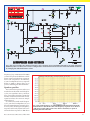
1
ENERGY METER M Monitors electricityy usage and cost BASS EXTENDER Extra bass from your speakers CARAVAN LIGHTTS LIGHTS T S CHEC HECK HEC CK Are your trailer lights working? Plus $6 95 US $8.99 $6.95 $8 99 CAN MAY 2007 PRINTED IN THE UK Copyright Ó 2007, Wimborne Publishing Ltd (408 Wimborne Road East, Ferndown, Dorset, BH22 9ND, UK) and TechBites Interactive Inc., (PO Box 857, Madison, Alabama 35758, USA) All rights reserved. WARNING! The materials and works contained within EPE Online — which are made available by Wimborne Publishing Ltd and TechBites Interactive Inc — are copyrighted. You are permitted to make a backup copy of the downloaded file and one (1) hard copy of such materials and works for your personal use. International copyright laws, however, prohibit any further copying or reproduction of such materials and works, or any republication of any kind. TechBites Interactive Inc and Wimborne Publishing Ltd have used their best efforts in preparing these materials and works. However, TechBites Interactive Inc and Wimborne Publishing Ltd make no warranties of any kind, expressed or implied, with regard to the documentation or data contained herein, and specifically disclaim, without limitation, any implied warranties of merchantability and fitness for a particular purpose. Because of possible variances in the quality and condition of materials and workmanship used by readers, EPE Online, its publishers and agents disclaim any responsibility for the safe and proper functioning of reader-constructed projects based on or from information published in these materials and works. In no event shall TechBites Interactive Inc or Wimborne Publishing Ltd be responsible or liable for any loss of profit or any other commercial damages, including but not limited to special, incidental, consequential, or any other damages in connection with or arising out of furnishing, performance, or use of these materials and works. EPE PROJECT PICs Programmed PICs for EPE Projects 12C508/9-£3.90; 16F627/8 - £4.90 16F84/71/ - £5.90 16F876/877/ 18Fxxxx - £10.00 All inc. VAT and Postage 1kV/500V Insulation Tester Super design. Regulated output and efficient circuit. Dual scale meter, compact case. Reads up to 200 Megohms. Kit includes wound ferrite transformer, drilled and punched case, meter scale, PCB & ALL components. (Needs PP3 battery). KIT 848...£32.95 DUAL OUTPUT TENS UNIT PIC PIPE DESCALER SIMPLE TO BUILD SWEPT FREQUENCY OUTPUT HIGH POWER AUDIO & VISUAL MONITORING An affordable circuit which sweeps the incoming water supply with varying frequency electromagnetic signals. May reduce scale formation, dissolve existing scale and improve the way salts in the water behave. Kit includes case PCB coupling coil and all components. High coil current ensures maximum effect. LED and piezo monitor. PIC WATER DESCALER 12V EPROM KIT 847 ... £63.95 Ultrasonic PEsT Scarers Two Ultrasonic PEsT Scarers. Kit 812 produces regular high level pulses of 32kHz. Kit 867 produces Random pulses and can work with an optional slave unit to give two separate ultrasound sources. Both kits need 9V supply. Kit 812 ... £14.81 psu . 3.99 Kit 867 ... £19.99 867Slave £12.51 MOSFET MKII Bench PSU 0-25V 2.5A Based on Mk1 design, with switching pre-regulator for high efficiency. Panel meters for A and V. Toroidal transformer. Variable Volts 0 - 25 AND Variable Current limit from 0 -2.5A Kit includes punched and labelled case. A classic and essential piece of test gear A safe low cost eraser for up to 4 EPROMS or other UV erasable windowed devices at a time in 20 minutes. Operates from a 12 Volt supply (400mA). Ideal for mobile work -and in educational applications where mains voltages are to be avoided. Safety interlock prevents contact with UV. PIC LCD DISPLAY DRIVER KIT 860.£19.99 PIC STEPPING MOTOR DRIVER PCB with components and PIC16F84 programmed with demonstration software to drive any 4 phase unipolar motor up to 24 Volts at 1 Amp. Kit includes 100 Step Hybrid Stepping Motor Full software source code supplied on disc. Use this project to develop your own applications. PCB allows ‘simple PIC programmer’ ‘SEND’ software to be used to reprogram chip. KIT 863.........£18.99 8 CHANNEL DATA LOGGER From Aug/Sept.’99 EPE. Featuring 8 analogue inputs and serial data transfer to PC. Magenta redesigned PCB - LCD plugs directly onto board. Use as Data Logger or as a test bed for developing other PIC16F877 projects. Kit includes lcd, programmed chip, PCB, Case, all parts and 8 x 256k EEPROMs KIT 877.........£49.95 SUPER PIC PROGRAMMER Magenta’s original parallel port programmer. Runs with downloaded WINDOWS 95 - XP software. Use standard Microchip .HEX files. Read/Prog/Verify wide range of 18,28,and 40 pin PICs. Including 16F84/876/877, 627/8, (Inc. ‘A’ versions) + 16xx OTPs. Kit 845 ... £64.95 68000 Trainer Kit 621.. 99.95 Stepping & DC Motors A range of motors for many applications: Visit our website for more details MD100 100 step Unipolar..... £9.99 MD200 200 step Unipolar..... £12.99 MD24 Type ‘23’ size 200 step..£22.95 A super walking programmable robot with eyes that sense obstacles and daylight. BrainiBorg comes with PC software CD (WIN95+ & XP) with illustrated construction details, and can be programmed to walk and respond to light and obstacles on any smooth surface. Kit includes all hardware, components, & 3 motor/gearboxes. Uses 4 AA batteries (not supplied). (Kit with CD Rom & Serial Lead) (As 912 but Built & Tested Circuit board) KIT 912 ... £29.99 KIT 913 ... £38.95 EPE PIC Toolkit 3 As in EPE Apr/May/Jun ‘03 and on PIC Resources CD Magenta Designed Toolkit 3 board with printed component layout, green solder mask, places for 8,18, 28 (wide and slim), and 40 pin PICs. and many Magenta extras. Also runs with WinPic800 prog. Software. 16 x 2 LCD, PIC chip all parts and sockets included. · Follow John Becker’s excellent ‘PIC tutorial 2’ series. 16F84 KIT 880 ... £34.99 (With Chip) (With 16F877 KIT 880 ... £39.99 Chip) OR - Built & Tested £49.99 & £55.99 EPE TEACH-IN 2004 COMPLETE 12 PART SERIES FROM NOV03 All parts to follow this Educational Electronics Course. Inc. Breadboard, and wire, as listed on p752 Nov 03’ KIT920..£29.99 Additional Parts as listed in ‘misc.’ Section (less RF modules, Lock, and Motor/g.box) KIT921.£12.99 Reprints £1.00 per part. KIT 862. £29.99 Power Supply £3.99 BAT DETECTORS ICEBREAKER Magenta’s Super Heterodyne Bat detectors. Our best selling kit 861 now includes a drilled case and front panel label. The MkIIb and digital MkIII are supplied built & ready to go Soft Zip Up Pouch for all 3....£5.99 KIT 861 .. £37.99 MkIIb .. £49.95 MkIII .. £89.95 All Prices Include VAT, Add £3.00 P&P per order, or £7.99 for next day. Chqs. P.O. & Most major cards accepted. See our Website for many more kits, products, & Secure On Line ordering. Mail Order Only. MAGENTA BRAINIBOT I & II · Full kit with ALL hardware and electronics. · As featured in EPE Feb ‘03 (KIT 910) · Seeks light, beeps, and avoids obstacles · Spins and reverses when ‘cornered’’ · Uses 8 pin PIC chip ALSO KIT 911 - As 910 PLUS programmable from PC serial port leads and software CD included. BrainiBorg ERASER KIT 866 .. £32.90 use. No ground effect - works in sea water. Detects Gold Silver, ferrous and non ferrous metals. Kit Includes Headphones, coil and all Hardware Latest Technology - Stable, Reliable, high performance IC with local feedback. (includes all parts & heatsink for stereo or mono) 16 Character x 2 Line dis- · Learn how to drive the display, pcb, programmed play and write your own PIC16F84, software disk and code. all components to experiment · Ideal development base for with standard intelligent al- meters, calculators, phanumeric displays. In- counters, timers --- just cludes full PIC source code waiting for your application which can be changed to · Top quality display with match your application. industry standard driver, data and instructions EPE MICROCHIP P.I. Treasure Hunter Stable Sensitive Pulse Induction detector. Easy to build and Short Circuit & Overheat Protected. Needs 8 to 18V supply. KIT 868 .. £22.95 PSU £3.99 KIT 790 ..... £29.90 Set of 4 Spare Electrodes £6.50 Wide band Low distortion 11W / channel Stereo 20W Mono. True (rms) Real Power KIT 914 ...... £11.90 An excellent kit for this project based on the EPE March’97 Design. Our Full Kit includes all components, hardware and an improved Magenta pcb. All hardware and electrodes are included. Designed for simple assembly and testing, providing a high level controlled dual output drive. Inc. 4 electrodes 20W Stereo Amp. EPE May ‘05 -- Magenta Stereo/Mono Module PIC Real Time In-Circuit Emulator With serial lead & software disk, PCB, Breadboard, PIC16F877, LCD, all components and patch leads. KIT910..£16.99 KIT911..£24.99 www.magenta2000.co.uk in EPE Mar’00 KIT 900..£34.99 · Featured Ideal for beginners & PSU £3.99 ICEbreaker uses PIC16F877 incircuit debugger functions. Tel: 01283 565435 experienced users. Windows (95 to XP) Software included Fax: 01283 546932 ELECTRONICS LTD 135 Hunter Street Burton on Trent Staffs DE14 2ST UK email: [email protected] HB7 Stirling Engine Base measurements: 128 mm x 108 mm x 170 mm, 1 kg Base plate: beech - Working rpm: 2000 rpm/min. (the engine has a aluminium good cooling Cylinder) Bearing application: 10 high-class ball-bearings Material: screw, side parts all stainless steel Cylinder brass, Rest aluminium and stainless steel. Available as a kit £80.75 or built £84.99 www.mamodspares.co.uk HB9 Stirling engine Base measurements: 156 mm x 108 mm x 130 mm, 0,6 Kg Base plate: beech Working rpm: approx. 2,000 min Bearing application: 6 high-class ball-bearings Material of the engine: brass, aluminium, stainless steel running time: 30-45 min. Available as a kit £97.75 or built £101.99 www.mamodspares.co.uk HB10 Stirling Engine Base measurements: 156 mm x 108 mm x 130 mm, 0,6 Kg Base plate: beech Working rpm: approx. 2,000 rpm Bearing application: 6 high-class ball-bearings Material of the engine: brass, aluminium, stainless steel running time: 30-45 min Available as a kit £97.75 or built £101.99 www.mamodspares.co.uk HB11 Stirling Engine Base measurements: 156 mm x 108 mm x 130 mm, 0,7 Kg Base plate: beech Working rpm: 2000 - 2500 rpm/min,run Bearing application: 4 high-class ball-bearings Material: screw, side parts total stainless steel Cylinder brass Rest aluminium, stainless steel. Available as a kit £97.75 or built £101.99 www.mamodspares.co.uk HB12 Stirling Engine Base measurements: 156 mm x 108 mm x 130 mm, 1 Kg Base plate: beech Working rpm: 2000 - 2500 rpm/min,Bearing application: 6 high-class ball-bearings Material: screw, side parts total stainless steel Cylinder brass Rest aluminium, stainless steel. Available as a kit £136 or built £140.25 www.mamodspares.co.uk STEAM ENGINE KIT Everything in the kit enables you to build a fully functional model steam engine. The main material is brass and the finished machine demonstrates the principle of oscillation. The boiler, uses solid fuel tablets, and is quite safe. All critical parts (boiler, end caps, safety vent etc.) are ready finished to ensure success. The very detailed instruction booklet (25 pages) makes completion of this project possible in a step by step manner. Among the techniques experienced are silver soldering, folding, drilling, fitting and testing. £29.70 ref STEAMKIT Silver solder/flux pack £3.50 ref SSK www.mamodspares.co.uk HB14 Stirling Engine Base measurements: 156 mm x 108 mm x 150 mm, 1 kg Base plate: beech Working rpm: 2000 - 2500 rpm/min, . Incl. drive-pulley for external drives Bearing application: 10 high-class ball-bearings Material: screw, side parts total stainless steelCylinder brass Rest aluminium, stainless steel Available as a kit £140.25 or built £144.50 www.mamodspares.co.uk HB15 Stirling Engine Base measurements: 128 mm x 108 mm x 170 mm, 0,75 kg Base plate: beech Working rpm: 2000 rpm/min. (the engine has a aluminium good cooling Cylinder) Bearing application: 6 high-class ball-bearings Material: screw, side parts total stainless steel Cylinder brass Rest aluminium, stainless steel Available as a kit £97.75 or built £102 www.mamodspares.co.uk Solar evacuated tube panels (20 tube shown) These top-of-the-range solar panel heat collectors are suitable for heating domestic hot water, swimming pools etc - even in the winter! One unit is adequate for an average household (3-4people), and it is modular, so you can add more if required. A single panel is sufficient for a 200 litre cylinder, but you can fit 2 or more for high water usage, or for heating swimming pools or underfloor heating. Some types of renewable energy are only available in certain locations, however free solar heating is potentially available to almost every house in the UK! Every house should have one -really! And with an overall efficiency of almost 80%, they are much more efficient than electric photovoltaic solar panels (efficiency of 7-15%). Available in 10, 20 and 30 tube versions. 10 tube £199, 20 tube £369, 30 tube £549. Roof mounting kits (10/20 tubes) £12.50, 30 tube mounting kit £15 BENCH PSU 0-15V 0-2a Output and voltage are both smooth and can be regulated according to work, Input 230V, 21/2-number LCD display for voltage and current, Robust PC-grey housing Size 13x15x21cm, Weight 3,2kg £48 REF trans2 HB16 Stirling Engine Base measurements: 128 mm x 108 mm x 170 mm, 1 kg Base plate: beech Working rpm: 2000 rpm/min. (the engine has a aluminium good cooling Cylinder) Bearing application: 10 high-class ball-bearings Material: screw, side parts total stainless steel Cylinder brass Rest aluminium, stainless steel. Available as a kit £140.25 or built £144.50 2kW WIND TURBINE KIT The 2kW wind turbine is supplied as the following kit: turbine generator 48v three taper/ twisted fibreglass blades & hub 8m tower (four x 2m sections) guylines / anchors / tensioners / clamps foundation steel rectifier 2kW inverter heavy-duty pivot tower. £1,499 BULL GROUP LTD HB13 Stirling Engine Base measurements: 156 mm x 108 mm x 150 mm, 0,75 kg Base plate: beech Working rpm: 2000 - 2500 rpm/min, Bearing application: 6 high-class ball-bearings Material: screw, side parts total stainless steel Cylinder brass Available as a kit £97.75 or built £101.99 Solar Panels We stock a range of solar photovoltaic panels. These are polycrystalline panels made from wafers of silicon laminated between an impact-resistant transparent cover and an EVA rear mounting plate. They are constructed with a lightweight anodised aluminium frame which is predrilled for linking to other frames/roof mounting structure, and contain waterproof electrical terminal box on the rear. 5 watt panel £29 ref 5wnav 20 watt panel £99 ref 20wnav 60 watt panel £249 ref 60wnav. Suitable regulator for up to 60 watt panel £20 ref REGNAV UNIT D HENFIELD BUSINESS PARK HENFIELD SUSSEX BN5 9SL TERMS: C/ CARDS, CASH, PO, CHEQUE OR ONLINE ORDERING. PRICES PLUS VAT UK DELIVERY £5.50 TEL 0870 7707520 FAX 01273 491813 [email protected] NEW ELECTRONIC CONSTRUCTION KITS This 30 in 1 electronic kit includes an introduction to electrical and electronic technology. It provides conponents that can be used to make a variety of experiments including Timers and Burglar Alarms. Requires: 3 x AA batteries. £15.00 ref BET1803 AM/FM Radio This kit enables you to learn about electronics and also put this knowledge into practice so you can see and hear the effects. Includes manual with explanations about the components and the electronic principles. Req’s: 3 x AA batts. £13 ref BET1801 This 40 in 1 electronic kit includes an introduction to electrical and electronic technology. It provides conponents that can be used in making basic digital logic circuits, then progresses to using Integrated circuits to make and test a variety of digital circuits, including Flip Flops and Counters. Req’s: 4 x AA batteries. £17 ref BET1804 The 75 in 1 electronic kit includes an nintroduction to electrical and electronic technology. It provides conponents that can be used to make and test a wide variety of experiments including Water Sensors, Logic Circuits and Oscillators. The kit then progresses to the use of an intergrated circuit to produce digital voice and sound recording experiments such as Morning Call and Burglar Alarm. Requires: 3 x AA batteries. £20 ref BET1806 www.slips.co.uk ISSN 0262 3617 PROJECTS . . . THEORY . . . NEWS . . . COMMENT . . . POPULAR FEATURES . . . VOL. 36. No. 5 I N C O R P O R AT I N G E L E C T RO N I C S TO DAY I N T E R N A T I O N A L www.epemag.co.uk EPE Online: www.epemag.com MAY 2007 Projects and Circuits ENERGY METER – PART 1 by John Clarke Control your power costs 12 CARAVAN LIGHTS CHECK by Terry de Vaux-Balbirnie Are your trailer lights working? 28 BASS EXTENDER by Rick Walters Pump up the bass response of your speakers 42 INGENUITY UNLIMITED – Sharing your ideas with others Ultra-Regulated LED; Courtesy Light Delay; Pico Prize Winners 52 SMS CONTROLLER ADD-ONS by Peter Smith Three external circuits for the SMS Controller: Test jig; PIR sensor and a low battery alarm 56 Series and Features TECHNO TALK by Mark Nelson Leaner and greener 10 PIC N’ MIX by Mike Hibbett PICs and ADCs 24 CIRCUIT SURGERY By Ian Bell Using a 4046 phase-locked loop IC 34 PRACTICALLY SPEAKING by Robert Penfold Front panel labels 48 NET WORK – THE INTERNET PAGE surfed by Alan Winstanley Failing memories; Remote backups; Price of restoration 64 Regulars and Services EDITORIAL 7 NEWS – Barry Fox highlights technology’s leading edge Plus everyday news from the world of electronics 8 CD-ROMS FOR ELECTRONICS A wide range of CD-ROMs for hobbyists, students and engineers 38 PLEASE TAKE NOTE Low-Cost 50MHz Frequency Meter; PIC Digital Geiger Counter 49 BACK ISSUES Did you miss these? 50 PIC RESOURCES CD-ROM EPE PIC Tutorial V2, plus PIC Toolkit Mk3 and a selections of PIC-related articles 54 ELECTRONIC MANUALS The Modern Electronics Manual and Electronics Service Manual on CD-ROM 58 THE POWER OF MECHATRONICS An EPE exclusive 59 SUBSCRIBE TO EPE and save money 60 READOUT John Becker addresses general points arising 61 DIRECT BOOK SERVICE A wide range of technical books available by mail order, plus more CD-ROMs 66 © Wimborne Publishing Ltd 2007. Copyright in all drawings, photographs and articles published in EVERYDAY PRACTICAL ELECTRONICS is fully protected, and reproduction or imitations in whole or in part are expressly forbidden. EPE PCB SERVICE PCBs for EPE projects 70 ADVERTISERS’ INDEX 72 Our June 2007 issue will be published on Thursday, 10 May 2007, see page 72 for details. Readers’ Services • Editorial and Advertisement Departments LOOK OUT FOR YOUR FREE CD-ROM NEXT MONTH! SEE PAGE 59 Everyday Practical Electronics, May 2007 7 1 Quasar Electronics Limited PO Box 6935, Bishops Stortford CM23 4WP, United Kingdom Tel: 0870 246 1826 Fax: 0870 460 1045 E-mail: [email protected] Web: www.QuasarElectronics.com All prices INCLUDE 17.5% VAT. Postage & Packing Options (Up to 2Kg gross weight): UK Standard 3-7 Day Delivery - £3.95; UK Mainland Next Day Delivery - £8.95; Europe (EU) - £6.95; Rest of World - £9.95 (up to 0.5Kg). !Order online for reduced price UK Postage! Payment: We accept all major credit/debit cards. Make cheques/PO’s payable to Quasar Electronics. Call now for our FREE CATALOGUE with details of over 300 kits, projects, modules and publications. Discounts for bulk quantities. Credit Card Sales Get Plugged In! PIC & ATMEL Programmers We have a wide range of low cost PIC and ATMEL Programmers. Complete range and documentation available from our web site. Programmer Accessories: 40-pin Wide ZIF socket (ZIF40W) £15.00 18Vdc Power supply (PSU010) £19.95 Leads: Parallel (LDC136) £4.95 / Serial (LDC441) £4.95 / USB (LDC644) £2.95 NEW! USB & Serial Port PIC Programmer USB/Serial connection. Header cable for ICSP. Free Windows XP software. See website for PICs supported. ZIF Socket and USB lead extra. 18Vdc. Kit Order Code: 3149KT - £37.95 Assembled Order Code: AS3149 - £49.95 NEW! USB 'All-Flash' PIC Programmer USB PIC programmer for all ‘Flash’ devices. No external power supply making it truly portable. Supplied with box and Windows XP Software. ZIF Socket and USB lead not incl. Assembled Order Code: AS3128 - £44.95 Assembled with ZIF socket Order Code: AS3128ZIF - £59.95 ‘PICALL’ ISP PIC Programmer Will program virtually all 8 to 40 pin serial-mode AND parallel-mode (PIC15C family) PIC microcontrollers. Free Windows software. Blank chip auto detect for super fast bulk programming. Optional ZIF socket. Assembled Order Code: AS3117 - £24.95 Assembled with ZIF socket Order Code: AS3117ZIF - £39.95 ATMEL 89xxxx Programmer Uses serial port and any standard terminal comms program. 4 LED’s display the status. ZIF sockets not included. Supply: 16Vdc. Kit Order Code: 3123KT - £24.95 Assembled Order Code: AS3123 - £34.95 Introduction to PIC Programming Go from complete beginner to burning a PIC and writing code in no time! Includes 49 page step-by-step PDF Tutorial Manual, Programming Hardware (with LED test section), Win 3.11—XP Programming Software (Program, Read, Verify & Erase), and 1rewritable PIC16F84A that you can use with different code (4 detailed examples provided for you to learn from). PC parallel port. Kit Order Code: 3081KT - £16.95 Assembled Order Code: AS3081 - £24.95 ABC Maxi AVR Development Board The ABC Maxi is ideal for developing new designs. Open architecture built around an ATMEL AVR AT90S8535 microcontroller. All circuits are embedded within the package and additional add-on expansion modules are available to assist you with project development. Features 8 Kb of In-System Programmable Flash (1000 write/erase cycles) Ɣ 512 bytes internal SRAM Ɣ 512 bytes EEPROM Ɣ 8 analogue inputs (range 05V) Ɣ 4 Opto-isolated Inputs (I/Os are bidirectional with internal pull-up resistors) Ɣ Output buffers can sink 20mA current (direct LED drive) Ɣ 4 x 12A open drain MOSFET outputs Ɣ RS485 network connector Ɣ 2-16 LCD Connector Ɣ 3.5mm Speaker Phone Jack Ɣ Supply: 9-12Vdc The ABC Maxi STARTER PACK includes one assembled Maxi Board, parallel and serial cables, and Windows software CDROM featuring an Assembler, BASIC compiler and in-system programmer. Order Code ABCMAXISP - £89.95 The ABC Maxi boards only can also be purchased separately at £69.95 each. Controllers & Loggers Here are just a few of the controller and data acquisition and control units we have. See website for full details. Suitable PSU for all units: Order Code PSU445 £8.95 Rolling Code 4-Channel UHF Remote State-of-the-Art. High security. 4 channels. Momentary or latching relay output. Range up to 40m. Up to 15 Tx’s can be learnt by one Rx (kit includes one Tx but more available separately). 4 indicator LED ’s. Rx: PCB 77x85mm, 12Vdc/6mA (standby). Two & Ten Channel versions also available. Kit Order Code: 3180KT - £44.95 Assembled Order Code: AS3180 - £51.95 Computer Temperature Data Logger Serial port 4-channel temperature logger. °C or °F. Continuously logs up to 4 separate sensors located 200m+ from board. Wide range of free software applications for storing/using data. PCB just 38x38mm. Powered by PC. Includes one DS1820 sensor and four header cables. Kit Order Code: 3145KT - £18.95 Assembled Order Code: AS3145 - £25.95 Additional DS1820 Sensors - £3.95 each Most items are available in kit form (KT suffix) or pre-assembled and ready for use (AS prefix). DTMF Telephone Relay Switcher Call your phone number using a DTMF phone from anywhere in the world and remotely turn on/off any of the 4 relays as desired. User settable Security Password, AntiTamper, Rings to Answer, Auto Hang-up and Lockout. Includes plastic case. 130 x 110 x 30mm. Power: 12Vdc. Kit Order Code: 3140KT - £46.95 Assembled Order Code: AS3140 - £59.95 Serial Port Isolated I/O Relay Module Computer controlled 8 channel relay board. 5A mains rated relay outputs and 4 optoisolated digital inputs (for monitoring switch states, etc). Useful in a variety of control and sensing applications. Programmed via serial port (use our new Windows interface, terminal emulator or batch files). Serial cable can be up to 35m long. Once programmed, unit can operate without PC. Includes plastic case 130x100x30mm. Power: 12Vdc/500mA. Kit Order Code: 3108KT - £54.95 Assembled Order Code: AS3108 - £64.95 Infrared RC 12–Channel Relay Board Control 12 onboard relays with included infrared remote control unit. Toggle or momentary. 15m+ range. 112 x 122mm. Supply: 12Vdc/0.5A Kit Order Code: 3142KT - £47.95 Assembled Order Code: AS3142 - £59.95 PC / Standalone Unipolar Stepper Motor Driver Drives any 5, 6 or 8-lead unipolar stepper motor rated up to 6 Amps max. Provides speed and direction control. Operates in stand-alone or PCcontrolled mode. Up to six 3179 driver boards can be connected to a single parallel port. Supply: 9Vdc. PCB: 80x50mm. Kit Order Code: 3179KT - £11.95 Assembled Order Code: AS3179 - £18.95 Bi-Polar Stepper Motor Driver also available (Order Code 3158 - details on website) DC Motor Speed Controller (100V/7.5A) Control the speed of almost any common DC motor rated up to 100V/7.5A. Pulse width modulation output for maximum motor torque at all speeds. Supply: 9-18Vdc. Box supplied. Dimensions (mm): 60Wx100Lx60H. Kit Order Code: 3067KT - £13.95 Assembled Order Code: AS3067 - £19.95 Bidirectional DC Motor Driver also available (Order Code 3166 - details on website) Hot New Kits This Summer! Here are a few of the most recent kits added to our range. See website or join our email Newsletter for all the latest news. EPE Ultrasonic Wind Speed Meter Solid-state design wind speed meter (anemometer) that uses ultrasonic techniques and has no moving parts and does not need calibrating. It is intended for sports-type activities, such as track events, sailing, hang-gliding, kites and model aircraft flying, to name but a few. It can even be used to monitor conditions in your garden. The probe is pointed in the direction from which the wind is blowing and the speed is displayed on an LCD display. Specifications N Units of display: metres per second, feet per second, kilometres per hour and miles per hour N Resolution: Nearest tenth of a metre N Range: Zero to 50mph approx. Based on the project published in Everyday Practical Electronics, Jan 2003. We have made a few minor design changes (see website for full details). Power: 9Vdc (PP3 battery). Main PCB: 50x83mm. Kit Order Code: 3168KT - £36.95 Audio DTMF Decoder and Display Detects DTMF tones via an onboard electret microphone or direct from the phone lines through an audio transformer. The numbers are displayed on a 16 character, single line display as they are received. Up to 32 numbers can be displayed by scrolling the display left and right. There is also a serial output for sending the detected tones to a PC via the serial port. The unit will not detect numbers dialled using pulse dialling. Circuit is microcontroller based. Supply: 9-12V DC (Order Code PSU445). Main PCB: 55x95mm. Kit Order Code: 3153KT - £20.95 Assembled Order Code: AS3153 - £29.95 EPE PIC Controlled LED Flasher This versatile PIC based LED or filament bulb flasher can be used to flash from 1 to 176 LEDs. The user arranges the LEDs in any pattern they wish. The kit comes with 8 super bright red LEDs and 8 green LEDs. Based on the Versatile PIC Flasher, EPE Magazine Dec 02. See website for full details. Board Supply: 912Vdc. LED supply: 9-45Vdc (depending on number of LED used). PCB: 43x54mm. Kit Order Code: 3169KT - £11.95 Most items are available in kit form (KT suffix) or assembled and ready for use (AS prefix). FM Bugs & Transmitters Our extensive range goes from discreet surveillance bugs to powerful FM broadcast transmitters. Here are a few examples. All can be received on a standard FM radio and have adjustable transmitting frequency. MMTX' Micro-Miniature 9V FM Room Bug Our best selling bug! Good performance. Just 25x15mm. Sold to detective agencies worldwide. Small enough to hide just about anywhere. Operates at the 'less busy' top end of the commercial FM waveband and also up into the more private Air band. Range: 500m. Supply: PP3 battery. Kit Order Code: 3051KT - £8.95 Assembled Order Code: AS3051 - £14.95 HPTX' High Power FM Room Bug Our most powerful room bug. Very impressive performance. Clear and stable output signal thanks to the extra circuitry employed. Range: 1000m @ 9V. Supply: 6-12V DC (9V PP3 battery clip supplied). 70x15mm. Kit Order Code: 3032KT - £9.95 Assembled Order Code: AS3032 - £17.95 MTTX' Miniature Telephone Transmitter Attach anywhere along phone line. Tune a radio into the signal and hear exactly what both parties are saying. Transmits only when phone is used. Clear, stable signal. Powered from phone line so completely maintenance free once installed. Requires no aerial wire - uses phone line as antenna. Suitable for any phone system worldwide. Range: 300m. 20x45mm. Kit Order Code: 3016KT - £7.95 Assembled Order Code: AS3016 - £13.95 Wide Band Synthesised FM Transmitter PLL based crystal-locked wide band FM transmitter delivering a high quality, stable 10mW output. Accepts both MIC audio signal (10mV) and LINE input (1v p-p) for example hi-fi, CD, audio mixer (like our kit 1052) or computer sound card. Supply: 9-15Vdc. Kit Order Code: 3172KT - £19.95 Assembled Order Code: AS3172 - £32.95 3 Watt FM Transmitter Small, powerful FM transmitter. Audio preamp stage and three RF stages deliver 3 watts of RF power. Use with the electret microphone supplied or any line level audio source (e.g. CD or tape OUT, mixer, sound card, etc). Aerial can be an open dipole or Ground Plane. Ideal project for the novice wishing to get started in the fascinating world of FM broadcasting. 45x145mm. Kit Order Code: 1028KT - £23.95 Assembled Order Code: AS1028 - £31.95 Get Plugged In! Electronic Project Labs Great introduction to the world of electronics. Ideal gift for budding electronics expert! 500-in-1 Electronic Project Lab Top of the range. Complete self-contained electronics course. Takes you from beginner to ‘A’ Level standard and beyond! Contains all the hardware and manuals to assemble 500 projects. You get 3 comprehensive course books (total 368 pages) - Hardware Entry Course, Hardware Advanced Course and a microprocessor based Software Programming Course. Each book has individual circuit explanations, schematic and connection diagrams. Suitable for age 12+. Order Code EPL500 - £149.95 Also available - 30-in-1 £15.95, 130-in-1 £37.95 & 300-in-1 £59.95 (details on website) Tools & Test Equipment We stock an extensive range of soldering tools, test equipment, power supplies, inverters & much more - please visit website to see our full range of products. Precision Digital Multitester (4.5 Digit) A highly featured, highprecision digital multimeter with a large 4.5 digit LCD display. High accuracy (0.05%). Autozeroing, polarity selection and over-range indication. Supplied complete with shrouded test leads, shock-proof rubber holster, built-in probe holder and stand. Supplied fully assembled with holster, battery and presentation box. Features include: Capacitance • Audio Frequency • Data Hold • hFE / Diode Test • Auto Power Off Technical Specifications DC voltage: 200mV-1000V • AC voltage: 2V-700V • DC current: 2mA-20A • AC current: 20mA-20A • Resistance: 200-200M • Capacitance: 2nF-20uF • Frequency: 20kHz • Max display: 19999 Order Code: MM463 - Was £44.95 Now on sale at just £29.95! See our website for more special offers! Secure Online Ordering Facilities Ɣ Full Product Listing, Descriptions & Photos Ɣ Kit Documentation & Software Downloads DGYHUWBHSHLQGG 4000 Series 4000B £0.27 4001B £0.16 4002B £0.19 4008B £0.23 4009UB £0.23 4010B £0.23 4011B £0.16 4012B £0.16 4013B £0.18 4014B £0.30 4015B £0.27 4016B £0.20 4017B £0.21 4018B £0.29 4019B £0.25 4020B £0.25 4021B £0.31 4022B £0.32 4023B £0.23 4024B £0.22 4025B £0.20 4026B £0.67 4027B £0.21 4028B £0.21 4029B £0.38 4030B £0.17 4035B £0.31 4040B £0.19 4041B £0.31 4042B £0.19 4043B £0.35 4047B £0.25 4048B £0.34 4049B £0.29 4049UB £0.17 4050B £0.20 4051B £0.23 4052B £0.32 4053B £0.22 4054B £0.56 4055B £0.34 4060B £0.16 4063B £0.41 4066B £0.18 4067B £2.20 4068B £0.19 4069UB £0.18 4070B £0.15 4071B £0.20 4072B £0.18 4073B £0.17 4075B £0.17 4076B £0.30 4077B £0.28 4078B £0.30 4081B £0.16 4082B £0.21 4085B £0.28 4086B £0.33 4093B £0.16 4094B £0.29 4098B £0.22 4099B £0.35 4502B £0.32 4503B £0.40 4508B £1.40 4510B £0.45 4511B £0.30 4512B £0.27 4515B £0.99 4516B £0.44 4518B £0.26 4520B £0.34 4521B £0.62 4526B £0.40 4527B £0.40 4529B £0.44 4532B £0.24 4536B £1.00 4538B £0.40 4541B £0.33 4543B £0.47 4555B £0.32 4556B £0.40 4584B £0.27 4585B £0.47 4724B £0.94 40106B £0.19 40109B £0.58 40174B £0.46 40175B £0.41 74HC Series 74HC00 £0.16 74HC02 £0.17 74HC03 £0.21 74HC04 £0.14 74HC08 £0.17 74HC10 £0.21 74HC11 £0.21 74HC14 £0.18 74HC20 £0.28 74HC27 £0.16 74HC30 £0.22 74HC32 £0.14 74HC42 £0.36 74HC73 £0.40 74HC74 £0.15 74HC75 £0.31 74HC85 £0.23 74HC86 £0.21 74HC107 £0.40 74HC123 £0.33 74HC125 £0.26 74HC126 £0.46 74HC132 £0.26 74HC133 £0.34 74HC137 £0.30 74HC138 £0.26 74HC139 £0.31 74HC151 £0.33 74HC153 £0.30 74HC154 £0.94 74HC157 £0.22 74HC158 £0.23 74HC161 £0.27 74HC162 £0.45 74HC163 £0.26 74HC164 £0.23 74HC165 £0.21 74HC173 £0.38 74HC174 £0.27 74HC175 £0.35 74HC193 £0.39 74HC195 £0.32 74HC240 £0.32 74HC241 £0.37 74HC244 £0.40 74HC245 £0.34 74HC251 £0.30 74HC253 £0.25 74HC257 £0.25 74HC259 £0.29 74HC273 £0.32 74HC299 £0.61 74HC365 £0.28 74HC367 £0.38 74HC368 £0.29 74HC373 £0.35 74HC374 £0.34 74HC390 £0.37 74HC393 £0.36 74HC563 £0.56 74HC573 £0.27 74HC574 £0.30 74HC595 £0.27 74HC597 £0.22 74HC688 £0.46 74HC4002 £0.31 74HC4017 £0.36 74HC4020 £0.36 74HC4040 £0.29 74HC4049 £0.31 74HC4051 £0.50 74HC4052 £0.34 74HC4053 £0.22 74HC4060 £0.23 74HC4075 £0.27 74HC4078 £0.32 74HC4511 £0.64 74HC4514 £0.84 74HC4538 £0.41 74HC4543 £0.90 74LS Series 74LS00 £0.38 74LS01 £0.14 74LS02 £0.22 74LS03 £0.29 74LS04 £0.30 74LS05 £0.14 74LS08 £0.19 74LS09 £0.15 74LS10 £0.27 74LS11 £0.17 74LS12 £0.25 74LS14 £0.33 74LS15 £0.24 74LS20 £0.27 74LS21 £0.20 74LS26 £0.17 74LS27 £0.25 74LS30 £0.20 74LS32 £0.23 74LS37 £0.31 74LS38 £0.18 74LS40 £0.14 74LS51 £0.24 74LS73 £0.36 74LS75 £0.30 74LS83 £0.38 74LS85 £0.48 74LS86 £0.25 74LS92 £0.45 74LS93 £0.58 74LS107 £0.30 74LS109 £0.21 74LS112 £0.24 74LS113 £0.23 74LS114 £0.36 74LS122 £0.31 74LS123 £0.31 74LS125 £0.28 74LS126 £0.25 74LS132 £0.47 74LS133 £0.36 74LS136 £0.23 74LS138 £0.33 74LS139 £0.26 74LS145 £0.56 74LS148 £0.64 74LS151 £0.29 74LS153 £0.38 74LS156 £0.36 74LS157 £0.22 74LS158 £0.21 74LS160 £0.48 74LS161 £0.32 74LS162 £0.44 74LS163 £0.32 74LS164 £0.43 74LS165 £0.48 74LS173 £0.24 74LS174 £0.24 74LS175 £0.30 74LS190 £0.60 74LS191 £0.27 74LS192 £0.60 74LS193 £0.43 74LS195 £0.24 74LS221 £0.41 74LS240 £0.32 74LS241 £0.32 74LS243 £0.30 74LS244 £0.41 74LS245 £0.45 74LS247 £0.60 www.esr.co.uk 74LS251 £0.24 74LS257 £0.24 74LS258 £0.24 74LS266 £0.14 74LS273 £0.32 74LS279 £0.24 74LS283 £0.47 74LS365 £0.21 74LS367 £0.21 74LS368 £0.21 74LS373 £0.39 74LS374 £0.38 74LS378 £0.62 74LS390 £0.34 74LS393 £0.33 74LS395 £0.26 74 Series 7407 £0.40 Linear ICs AD524AD £23.04 AD548JN £2.48 AD590JH £5.28 AD595AQ £13.92 AD620AN £9.88 AD625JN £16.20 AD633JN £5.92 AD648JN £2.57 AD654JN £5.51 AD711JN £1.97 AD712JN £2.51 AD736JN £5.80 AD797AN £7.25 AD811N £6.00 AD812AN £6.32 AD820AN £3.41 AD822AN £5.20 AD829JN £6.41 AD830AN £5.44 AD847JN £5.95 AD9696KN £7.73 ADEL2020A £5.06 ADM222AH £3.55 ADM232AA £3.55 ADM485JN £2.97 ADM666AN £2.72 ADM690AN £5.13 ADM691AN £6.48 ADM695AN £6.48 ADM699AN £3.58 CA3046 £0.65 CA3130E £0.87 CA3140E £0.63 CA3240E £0.91 DG211CJ £1.25 DG411DJ £2.00 ICL7106CPL £2.21 ICL7107CPL £2.06 ICL7109CLP £5.76 ICL7611DCP £1.00 ICL7621 £0.84 ICL7660SCP £0.80 ICM7555 £0.41 ICM7556 £1.04 L165V £2.36 L272M £1.21 L293E £4.20 L297 £5.12 L298N £6.67 L4960 £2.81 L6219 £4.48 LF347N £0.46 LF351N £0.44 LF353N £0.40 LF356 £0.52 LM311N8 £0.17 LM319N14 £0.90 LM324 £0.20 LM335Z £1.12 LM339N £0.18 LM348N £0.36 LM35DZ £0.97 LM358N £0.13 LM380N £0.90 LM386 £0.45 LM392N £0.79 LM393N £0.21 LM1881 £2.90 LM2901N £0.15 LM2917N8 £1.98 LM3900N £0.72 LM3914 £1.97 LM3915 £2.24 LM13700 £1.35 LMC660CN £1.26 LMC6032IN £1.55 LP311N £0.74 LP324N £0.75 LP339N £0.75 LT1013CN8 £4.64 M34-1 £0.30 M34-2 £0.30 MAX202CPE £2.00 MAX208CN £6.99 MAX220CPE £5.06 MAX222CPE £5.06 MAX232CPE £1.30 MAX483CP £3.13 MAX485CP £2.04 MAX631ACP £4.99 MAX635ACP £4.99 MAX1232CP £2.80 MC1458N £0.27 MC1488 £0.40 MC1489 £0.35 MC3302 £0.56 MC4558P £0.40 MK484 £0.66 NE521N £6.39 NE555N £0.16 NE556N £0.24 NE565N £2.30 NE592 £0.62 NE5532N £0.48 NE5534N £0.54 NE5539N £4.35 03 07 OP27CN £2.33 OP90GP £2.91 OP97FP £1.84 OP113GP £3.44 OP176GP £2.09 OP177GP £2.18 OP200GP £5.60 OP213FP £5.20 OP275GP £2.57 OP282GP £2.27 OP283GP £5.20 OP290GP £4.28 OP297GP £4.64 OP400GP £11.81 OP495GP £8.69 RC4136 £1.00 SG3524N £0.82 SG3543 £6.88 SSM2141P £3.21 SSM2142P £6.16 SSM2143P £3.78 TBA120S £1.04 TBA800 £0.75 TBA810S £0.64 TBA820M £0.53 TDA1170S £4.80 TDA2004 £2.24 TDA2030AV £1.24 TDA2050V £2.51 TDA2611A £1.88 TDA2822A £0.79 TDA2653A £2.99 TED3718DP £5.03 TEA5115 £3.11 TL061CP £0.21 TL062CP £0.21 TL064CN £0.29 TL071CN £0.30 TL072CN £0.40 TL074CN £0.25 TL081CN £0.17 TL082CN £0.32 TL084CN £0.37 TL7705ACP £0.82 TLC271 £0.63 TS272CN £0.57 TS274CN £0.50 TS555CN £0.40 TMP01FP £5.60 UA741CN £0.18 ULN2003A £0.38 ULN2004A £0.44 ULN2803A £0.42 ULN2804A £0.41 EPROM’s 24LC08BP £0.73 24LC16BP £0.69 24LC32AP £1.14 27128-200 £3.99 27256-200 £3.99 27C64A-15F £3.99 27C256B-15F£3.00 27C512-15F1£2.85 27C1001-15. £3.17 27C2001-15. £4.41 27C4001-10F£5.98 93C46N £0.33 RAM GM76C88. £3.60 A/D Converters Data Acquisition AD420AN £25.38 AD7528JN £11.42 AD7545AK £14.04 AD7828KN £20.33 DAC0800 £2.40 ICL7109CPL £7.75 uControllers AT89C2051 £6.38 PIC Series 12C508A04P £0.78 12C509A04P £0.83 16C54C04P £1.49 16C54BJW £7.60 16C56A-04P £1.58 16F84-04P £3.14 16F84-10P £4.16 16F627-04P £1.65 16F627-20IP £1.80 17F628-20IP £2.40 16F867-04SP £5.10 16F877-20P £5.79 Voltage Regulators 7805 £0.27 7806 £0.29 7808 £0.27 7812 £0.23 7815 £0.27 78L05 £0.22 78L06 £0.32 78L08 £0.22 78L12 £0.16 78L15 £0.26 78L24 £0.39 78S05 £0.53 78S12 £0.42 78S15 £0.32 7905 £0.23 7912 £0.24 7915 £0.22 7924 £0.38 79L05 £0.20 79L12 £0.26 79L15 £0.28 79L24 £0.30 ADM666AN £3.44 L200CV £1.67 L296 £4.42 LM2940CT5 £0.75 LM317LZ £0.25 LM317T £0.30 LM317K £2.28 LM323K £2.40 LM334Z £0.96 LM337T £0.64 LM338K £5.31 LM338T £1.10 LM723 £0.40 LP2950CZ5.0 £0.72 REF01CP £2.31 REF195GP £3.04 TL431CP £0.14 Diodes 1N914 £0.05 1N916 £0.05 1N4001 £0.04 1N4002 £0.05 1N4003 £0.03 1N4004 £0.04 1N4005 £0.04 1N4006 £0.04 1N4007 £0.03 1N4148 £0.03 1N4149 £0.07 1N5400 £0.08 1N5401 £0.08 1N5402 £0.08 1N5404 £0.09 1N5406 £0.10 1N5407 £0.10 1N5408 £0.10 6A05 £0.27 6A1 £0.30 6A2 £0.27 6A4 £0.28 6A6 £0.32 6A8 £0.30 6A10 £0.35 BA157 £0.07 BA158 £0.08 BA159 £0.13 BAT41 £0.12 BAT42 £0.07 BAT46 £0.12 BAT85 £0.09 BAV21 £0.07 BAW62 £0.07 BAX16 £0.05 BY127 £0.18 BY133 £0.10 OA47 £0.70 OA90 £0.33 OA91 £0.32 OA200 £0.56 UF4001 £0.08 UF4002 £0.08 UF4003 £0.09 UF4004 £0.08 UF4005 £0.10 UF4006 £0.10 UF4007 £0.14 Zeners 2.7 to 33V 500mW £0.06 1.3W £0.10 Bridge Rectifiers 1A 50V £0.35 1A 100V £0.32 1A 200V £0.39 1A 600V £0.40 1A 800V £0.43 1.5A 50V £0.19 1.5A 100V £0.11 1.5A 200V £0.19 1.5A 400V £0.20 1.5A 600V £0.24 1.5A 800V £0.26 1.5A 1kV £0.18 2A 100V £0.34 2A 200V £0.34 2A 400V £0.35 2A 800V £0.36 2A 1000V £0.45 3A 200V £0.34 3A 400V £0.40 3A 600V £0.33 3A 1000V £0.33 4A 100V £0.78 4A 200V £0.80 4A 400V £0.86 4A 600V £0.90 6A 100V £0.49 6A 200V £0.64 6A 400V £0.53 6A 600V £0.67 6A 800V £0.37 8A 100V £0.98 8A 200V £1.00 8A 400V £1.20 8A 600V £1.33 8A 1000V £1.05 25A 100V £1.47 25A 200V £1.54 25A 400V £1.98 25A 600V £1.82 35A 50V £1.67 35A 100V £1.57 35A 200V £1.80 35A 400V £1.44 35A 600V £1.90 35A 1000V £2.32 Thyristors 2N5060 £0.19 2N5061 £0.19 BT151-500R £0.65 C106D1 £0.36 PO102AA £0.30 TIC106D £0.49 TIC116D £0.66 TIC126D £0.77 Triacs BT136-500 £0.58 BT136-600 £0.50 BT137-600 £0.58 BT139-500 £1.00 BT139-600 £1.20 BTA08-600B £0.84 BTA08-600BW£0.76 BTA08-600C £0.96 BTA08-600SW£0.93 BTA08-600TW£1.10 BTA12-600BW£0.92 BTA16-600CW £1.45 BTA16-600B £1.28 BTA26-600B £2.78 TIC206D £0.70 TIC206M £0.75 TIC226D £0.80 TIC226M £1.00 TIC246D £1.00 TIC246M £1.00 TIC236D £1.12 ZO105DA £0.53 Diac DB3, 32V £0.08 Transistors 2N2222A £0.20 2N2369A £0.51 2N2646 £1.02 2N2904A £0.35 2N2905A £0.30 2N2907A £0.28 2N3053 £0.38 2N3054 £0.85 2N3055 £0.58 2N3439 £0.62 2N3440 £0.50 2N3702 £0.09 2N3703 £0.10 2N3704 £0.11 2N3705 £0.08 2N3771 £1.44 2N3772 £1.72 2N3773 £2.30 2N3819 £0.27 2N3903 £0.11 2N3904 £0.05 2N3905 £0.10 2N3906 £0.05 2N4401 £0.08 2N4403 £0.09 2N5245 £0.80 2N5296 £0.57 2N5401 £0.12 2N5551 £0.07 2N6491 £1.58 2N7000 £0.19 2SB548 £0.30 AC127 £0.50 AC187 £0.68 AC188 £0.97 ACY17 £4.84 AD149 £1.29 AD161 £0.73 AD162 £0.95 BC107 £0.15 BC107B £0.14 BC108 £0.18 BC108B £0.14 BC108C £0.18 BC109 £0.19 BC109C £0.16 BC114 £0.19 BC115 £0.41 BC118 £0.41 BC132 £0.36 BC134 £0.36 BC135 £0.36 BC140 £0.75 BC142 £0.50 BC143 £0.38 BC159 £0.17 BC160 £0.28 BC170B £0.16 BC171B £0.16 BC177 £0.25 BC178 £0.18 BC179 £0.15 BC182B BC182L BC183L BC184 BC184L BC206B BC208 BC209A BC212L BC213L BC214 BC214L BC225 BC237B BC238B BC250A BC261B BC262B BC267B BC319C BC327 BC327-25 BC328 BC337-16 BC337-25 BC348B BC357 BC393 BC461 BC463 BC477 BC479 BC516 BC517 BC546B BC546C BC547A BC547B BC547C BC548A BC548B BC548C BC549B BC549C BC550C BC556A BC556B BC557A BC557B BC557C BC558A BC558B BC559A BC560A BC636 BC637 BC638 BC639 BC640 BCY72 BD124P BD131 BD132 BD135 BD136 BD137 BD138 BD139 BD140 BD150C BD201 BD202 BD232 BD237 BD238 BD240C BD245C BD246C BD283 BD284 BD400 BD437 BD438 BD442 BD534 BD535 BD646 BD648 BD650 BDX32 BDX34C BDX53C BDX54C BF180 BF182 BF245B BF257 BF259 £0.09 £0.11 £0.09 £0.09 £0.13 £0.72 £0.72 £0.72 £0.09 £0.12 £0.11 £0.10 £0.15 £0.11 £0.11 £0.15 £0.30 £0.24 £0.36 £0.13 £0.08 £0.08 £0.09 £0.10 £0.08 £0.14 £0.25 £0.73 £0.41 £0.29 £0.52 £0.32 £0.21 £0.14 £0.06 £0.08 £0.09 £0.09 £0.10 £0.08 £0.09 £0.08 £0.09 £0.09 £0.11 £0.08 £0.10 £0.09 £0.09 £0.09 £0.08 £0.09 £0.08 £0.09 £0.10 £0.19 £0.21 £0.09 £0.12 £0.20 £6.86 £0.48 £0.46 £0.22 £0.21 £0.23 £0.19 £0.19 £0.14 £0.82 £0.40 £0.70 £0.50 £0.32 £0.44 £0.37 £1.10 £1.18 £0.61 £0.61 £0.79 £0.17 £0.22 £0.37 £0.47 £0.50 £0.52 £0.52 £0.53 £1.78 £0.45 £0.53 £0.50 £0.31 £0.31 £0.40 £0.33 £0.33 BF337 £0.40 BF422 £0.15 BF423 £0.15 BF459 £0.33 BF469 £0.36 BFX29 £0.29 BFX84 £0.31 BFX85 £0.33 BFX88 £0.27 BFY50 £0.30 BFY51 £0.22 BFY52 £0.24 BS107 £0.21 BS170 £0.15 BU208A £1.53 BU326A £1.40 BU500 £1.54 BU508A £1.40 BU508D £0.98 BU806 £1.06 BUT11AF £1.14 BUX84 £0.78 BUZ900 £7.68 BUZ900P £5.60 BUZ905 £7.68 BUZ905P £5.60 IRF530 £0.53 IRF540 £0.78 IRF630 £0.42 IRF640 £0.63 IRF730 £0.66 IRF740 £0.91 IRF830 £0.68 IRF840 £0.78 MJ2955 £0.90 MJ2501 £1.60 MJ3001 £1.84 MJ11015 £2.45 MJ11016 £2.78 MJE340 £0.33 MJE350 £0.32 MPSA05 £0.14 MPSA13 £0.09 MPSA42 £0.14 MPSA55 £0.13 MPSA56 £0.12 STP14NF10 £0.49 STW80NE-10£3.80 TIP29A £0.32 TIP29C £0.33 TIP30A £0.47 TIP30C £0.27 TIP31A £0.23 TIP31C £0.35 TIP32A £0.29 TIP32C £0.30 TIP33C £0.74 TIP41A £0.32 TIP41C £0.32 TIP42A £0.47 TIP42C £0.43 TIP50 £0.28 TIP110 £0.28 TIP120 £0.30 TIP121 £0.32 TIP122 £0.24 TIP125 £0.31 TIP126 £0.31 TIP127 £0.35 TIP132 £0.50 TIP137 £0.64 TIP141 £0.93 TIP142 £0.93 TIP147 £1.07 TIP2955 £0.46 TIP3055 £0.46 ZVN2106A £0.40 ZVN3306A £0.28 ZVN4206A £0.52 ZVN4210A £0.56 ZVN4306A £0.74 ZVN4310A £0.88 ZVP2106A £0.42 ZVP2110A £0.46 ZVP3306A £0.32 ZTX302 £0.17 ZTX450 £0.19 ZTX451 £0.21 ZTX453 £0.26 ZTX502 £0.17 ZTX550 £0.22 ZTX551 £0.33 ZTX600 £0.33 ZTX600B £0.35 ZTX605 £0.36 ZTX651 £0.33 ZTX653 £0.37 ZTX689B £0.40 ZTX690B ZTX705 ZTX750 ZTX751 ZTX753 ZTX789A ZTX790A ZTX851 ZTX853 ZTX951 ZTX1048A ZTX1051A ZTX1053A £0.37 £0.39 £0.25 £0.34 £0.40 £0.41 £0.41 £0.50 £0.50 £0.54 £0.48 £0.46 £0.45 NEW ONLINE Transformers Large selection of mains & audio transformers. Fuses 20mm, 32mm Quick Blow & Time-lag Glass, Ceramic www.esr.co.uk Potty about Pots! We now carry in stock a wide range of positive position pots. With either with a centre click or 41 click positions. Log, Lin, Single or Dual gang. Quality Components No surplus or redundant stock. All from leading manufactures. Quality Service Sameday despatch on all stock items. Friendly helpful staff. Fast Delivery Nextday service for all orders at no extra charge. No Minimum Order Order what you need, no pack quantities or min order value. Quantity Discounts Available We offer discounts for all items subject to quantity required, phone, fax or email for a quote. We carry a large range of capacitors in stock, including: Ceramic Mini Disc, Dipped Ceramic Multilayer, Dipped & Boxed Polyester, Mylar Film, Polystyrene, Plastic Film, MKT Polyester, Tantalum Bead, Sub-miniature Radial, 105°C Radial, Low Leakage Radial, Non Polarised Radial & Axial, PCB Can Electrolytics, Polypropylene & Ceramic Trimmers and Tuning capacitors. Full technical details available. per 100 of one Resistors - Please State Value Required value only 1/8W Carbon Film 5% E12 Series 10W-1M0 £0.02 Each, £0.80 per 100 ¼W Carbon Film 5% E12 Series 1W-10M £0.02 Each, £0.60 per 100 ¼W Metal Film 1% E24 Series 10W-1M £0.04 Each, £1.72 per 100 ½W Carbon Film 5% E12 Series 1W-10M £0.02 Each, £0.95 per 100 2.5W Wirewound 5% E12 Series 0W1-220W £0.23 Each 1W, 2W, 5W, 20W, 25W & 50W also in stock - selected values only, contact sales dept. Always online! Our catalogue is available to view or download. Up to date with new products & prices Preset Resistors - Please State Value Required Enclosed, 10mm Square Horz / Vert. 100W - 1M0 0.15W Skeleton, 10mm Dia. Horizontal. 100W - 1M0 0.1W Sub-min, 6mm Dia, Horizontal E3 200W-1M0 0.1W Multiturn, 10mm Square, Top Adjust. E3 100W-1M0 0.5W Multiturn, 19mm Long, End Adjust. E3 50W-1M0 0.5W Potentiometers - Please State Value Required Single Gang ¼” Shaft, 25mm Dia. 470W-2M2 Linear Single Gang ¼” Shaft, 25mm Dia. 4k7,10k,47k,100k,1M,2M2 Log Dual Gang¼” Shaft, 20mm Dia. 1k0-2M2 Linear Dual Gang¼” Shaft, 20mm Dia. 10k-470k Logarithmic Switched ¼” Shaft, 20mm Dia. 1k0-2M2 Linear Switched ¼” Shaft, 20mm Dia. 4k7-2M2 Logarithmic PCB Mount, Splined Shaft, 16mm Dia. 470W-1M0 Linear PCB Mount, Splined Shaft, 16mm Dia. 470W,4k7,100k,1M0 Log Dual PCB, Splined Shaft, 16mm Dia. 10k,50k100k,500k Lin Dual PCB, Splined Shaft, 16mm Dia. 10k,50k,100k,500k Log Tel: 0191 2514363 Fax: 0191 2522296 [email protected] Station Road Cullercoats Tyne & Wear NE30 4PQ £0.12 £0.09 £0.12 £0.81 £0.59 Each Each Each Each Each £0.56 Each £0.56 Each £1.54 Each £1.54 Each £1.92 Each £1.92 Each £0.48 Each £0.56 Each £1.05 Each £1.00 Each Prices Exclude Vat @17½%. UK Carriage £2.50 (less than 1kg) £5.50 greater than 1kg or >£30 Cheques / Postal orders payable to ESR Electronic Components. PLEASE ADD CARRIAGE & VAT TO ALL ORDERS THE UK’s No.1 MAGAZINE FOR ELECTRONICS TECHNOLOGY & COMPUTER PROJECTS VOL. 36 No. 5 MAY 2007 Editorial Offices: EVERYDAY PRACTICAL ELECTRONICS EDITORIAL Wimborne Publishing Ltd., 408 Wimborne Road East, Ferndown, Dorset BH22 9ND Phone: (01202) 873872. Fax: (01202) 874562. Email: [email protected] Web Site: www.epemag.co.uk EPE Online (downloadable version of EPE): www.epemag.com EPE Online Shop: www.epemag.wimborne.co.uk/shopdoor.htm See notes on Readers’Technical Enquiries below – we regret technical enquiries cannot be answered over the telephone. Advertisement Offices: EVERYDAY PRACTICAL ELECTRONICS ADVERTISEMENTS 408 Wimborne Road East, Ferndown, Dorset BH22 9ND Phone: 01202 873872 Fax: 01202 874562 Email: [email protected] Teach-In Our Teach-In 2006 series of eleven parts finished in the September ’06 issue; written by Mike Tooley, this series was very popular and such is the demand for back issues that seven of them have now sold out. To meet the on-going demand we have produced the whole series in book form. In addition to the book, Mike has also produced an Electronics Teach-In CDROM which comes free with the book. The CD-ROM contains TINA circuit simulation software, Flowcode PIC programming software (both are time limited versions), Interactive Quizzes to test your understanding of the series and the full series in PDF form, plus various links to relevent websites. Mike has also written a special TINA Tutorial and set up the test and demonstration circuits from the series in the TINA package, so that you can test and modify each one on-screen and see the results on virtual meters and oscilloscopes etc. It brings the whole series to life without the need to assemble components – although full breadboard layouts for the demonstration circuits are also provided. Projects In addition to the full Teach-In series, the book also contains the whole Back To Basics series of CMOS projects previously published in 2005. This series of 15 projects was based around CMOS logic devices and, following a short introduction to CMOS and the chips used, describes the following inexpensive, easy-to-build projects: Fridge/Freezer Door Alarm, Water Level Detector; Burglar Alarm, Scarecrow, Digital Lock, Door Chime, Electronic Dice, Kitchen Timer, Room Thermometer, Daily Reminder, Whistle Switch, Parking Radar, Telephone Switch, Noughts and Crosses Enigma and a Weather Vane. Each project is PCBbased with full constructional details, and boards are available from our PCB Service. There is also a MW/LW Radio Receiver project included in the last part of the Teach-In series. All in all, we believe this is an excellent package which will be of interest to everyone learning about electronics, to those that want to brush up on their theory and anyone interested in building simple projects and understanding what goes on inside them. The book (with the free CD-ROM) is now available from larger WHSmith stores or by mail order from our Direct Book Service – see page 66, or go to the Online Shop on our UK website at www.epemag.co.uk AVAILABILITY Copies of EPE are available on subscription anywhere in the world (see opposite) and from all UK newsagents (distributed by SEYMOUR). EPE can also be purchased from retail magazine outlets around the world. An Internet on-line version can be purchased and downloaded for just $15.99US (approx £9.00) per year available from www.epemag.com SUBSCRIPTIONS Subscriptions for delivery direct to any address in the UK: 6 months £18.75, 12 months £35.50, two years £66; Overseas: 6 months £21.75 standard air service or £30.75 express airmail, 12 months £41.50 standard air service or £59.50 express airmail, 24 months £78 standard air service or £114 express airmail. To subscribe from the USA or Canada call Express Mag toll free on 1877-363-1310 Online subscriptions, for downloading the magazine via the Internet, $15.99US (approx £9.00) for one year available from www.epemag.com. Cheques or bank drafts (in £ sterling only) payable to Everyday Practical Electronics and sent to EPE Subs. Dept., Wimborne Publishing Ltd. 408 Wimborne Road East, Ferndown, Dorset BH22 9ND. Tel: 01202 873872. Fax: 01202 874562. Email: [email protected]. Also via the Web at: http://www.epemag.wimborne.co.uk. Subscriptions start with the next available issue. We accept MasterCard, Amex, Diners Club, Maestro or Visa. (For past issues see the Back Issues page.) BINDERS Binders to hold one volume (12 issues) are available from the above address. These are finished in blue PVC., printed with the magazine logo in gold on the spine. Price £7.95 plus £3.50 p&p (for overseas readers the postage is £6.00 to everywhere except Australia and Papua New Guinea which cost £10.50). Normally sent within seven days, but please allow 28 days for delivery – more for overseas. Payment in £ sterling only please. Visa, Amex, Diners Club, Maestro and MasterCard accepted. Send, fax or phone your card number, card expiry date and card security code (the last 3 digits on or just under the signature strip), with your name, address etc. Or order on our secure server via our UK web site. Overseas customers – your credit card will be charged by the card provider in your local currency at the existing exchange rate. Everyday Practical Electronics, May 2007 Editor: MIKE KENWARD Consulting Editors: DAVID BARRINGTON JOHN BECKER Business Manager: DAVID J. LEAVER Subscriptions: MARILYN GOLDBERG General Manager: FAY KEARN Editorial/Admin: (01202) 873872 Advertising Manager: STEWART KEARN (01202) 873872 On-line Editor: ALAN WINSTANLEY EPE Online (Internet version) Editors: CLIVE (MAX) MAXFIELD and ALVIN BROWN READERS’ TECHNICAL ENQUIRIES E-mail: [email protected] We are unable to offer any advice on the use, purchase, repair or modification of commercial equipment or the incorporation or modification of designs published in the magazine. We regret that we cannot provide data or answer queries on articles or projects that are more than five years’ old. Letters requiring a personal reply must be accompanied by a stamped self-addressed envelope or a selfaddressed envelope and international reply coupons. We are not able to answer technical queries on the phone. PROJECTS AND CIRCUITS All reasonable precautions are taken to ensure that the advice and data given to readers is reliable. We cannot, however, guarantee it and we cannot accept legal responsibility for it. A number of projects and circuits published in EPE employ voltages that can be lethal. You should not build, test, modify or renovate any item of mains-powered equipment unless you fully understand the safety aspects involved and you use an RCD adaptor. COMPONENT SUPPLIES We do not supply electronic components or kits for building the projects featured, these can be supplied by advertisers. We advise readers to check that all parts are still available before commencing any project in a back-dated issue. ADVERTISEMENTS Although the proprietors and staff of EVERYDAY PRACTICAL ELECTRONICS take reasonable precautions to protect the interests of readers by ensuring as far as practicable that advertisements are bona fide, the magazine and its publishers cannot give any undertakings in respect of statements or claims made by advertisers, whether these advertisements are printed as part of the magazine, or in inserts. The Publishers regret that under no circumstances will the magazine accept liability for non-receipt of goods ordered, or for late delivery, or for faults in manufacture. TRANSMITTERS/BUGS/TELEPHONE EQUIPMENT We advise readers that certain items of radio transmitting and telephone equipment which may be advertised in our pages cannot be legally used in the UK. Readers should check the law before buying any transmitting or telephone equipment, as a fine, confiscation of equipment and/or imprisonment can result from illegal use or ownership. The laws vary from country to country; readers should check local laws. 7 News . . . A roundup of the latest Everyday News from the world of electronics S-10 pocket camcorder Panasonic has upset the status quo by introducing a HDTV camcorder with no moving parts. Barry Fox reports. Thirty years ago, fleet-footed JVC caught its big and cumbersome parent Panasonic on the hop by inventing VHS and then being first with a truly portable VHS-C camcorder. JVC was first with a pocket DV camcorder and then re-wrote the camcorder rulebook once again with the Everio hard disc devices – first using removable IBM Microdrives, and later (when the Microdrive price did not fall as JVC expected) a fixed hard drive with sufficient data capacity to capture a holiday’s worth of video. Now it is parent company Panasonic’s turn to upset the status quo. At a recent seminar in Italy, Panasonic unveiled a hedge-betting range of camcorders that use every imaginable method of storing video, not just DV tape and 8cm recordable DVD, but also solid state memory cards. The big breakthrough is capturing useful amounts of HDTV in solid state. The new S-10 pocket camcorder shoots Standard Definition MPEG-2 digital video direct to an SD memory card. Because there are no moving parts, it can be dropped from 1.2 metres, blown with beach sand and sprayed with snow or water. Also, the lack of mechanics to move means the camera is ready to shoot and capture in 1.7 seconds, which is less than half the usual start up time for disc or tape. Because there is so little inside the case it is palm size and will sell for around 400 Euros. The camera comes with a 2GB card which stores around 50 minutes of standard definition video, equivalent in quality to DV tape. The SD-1 raises the quality bar by using a three-CCD image sensor to shoot HDTV direct to an SD card. The unconfirmed, but likely price of 1200 Euros, includes a 4GB card which will hold an hour of HD video. The camera body has five mini microphones on the top to capture 5.1 Dolby Digital surround sound. This immediately prompts the question, how can it be possible to store an hour of HDTV and 5.1 surround on a 4GB card? AVCHD Recording Standard The SD-1 uses the new AVCHD recording standard developed by Sony and Panasonic. AVCHD is a flavour of MPEG4, the compression system used by Sky for HDTV. There are three data rate options, 13Mbps which gives the best quality and gets 40 minutes from a 4GB card, 9Mbps for the round hour and 6Mbps for 90 minutes. The AVCHD standard is new and still 8 emerging. There is no editing software yet, but packages are coming soon from the likes of Pinnacle and Adobe. The Panasonic camera claims full HD resolution, which is widescreen 1920 × 1080 pixels, but actually – Panasonic admits when quizzed – captures only 1440 × 1080 which is not supported by HDMI. The Panasonic camera upscales for HDMI connection to a TV or Blu-ray recorder. “If we used full 1920 pixel resolution the camcorder would consume too much power and be too hot to hold” explained one of Panasonic’s design engineers. “Also, recording 1920 pixels would need more bit rate and reduce recording time. So we record at 1440 and upscale from 1920 × 1080 in the camera”. Even with this compromise the picture quality is very impressive and Panasonic’s new Mega Optical Image Stabiliser system uses a gyroscope sensor to detect and correct for handshake by physically moving the lens. There are already plans for 8GB and 16GB SD cards, with 32GB promised. The price is still considerably above tape, but the way computer and camera memory prices have tumbled over the last year gives a clear pointer to where the camcorder market is going next. The use of AVCHD is especially significant after comments made by Etsuji Shuda, Panasonic’s AV Business Group Executive. First, and with no surprises, he repeated the confident line started by the Blu-ray Disc Group at CES in Las Vegas that “BD is becoming the de facto standard, with seven out of eight studios committed to BD and only 10% of movie titles available only on HD-DVD”. BD-10A Blu-ray Player Shuda then unveiled the new BD-10A Bluray player. Cosmetically similar to the BD10, the new model supports 7.1 Dolby True HD and DTS HD lossless audio. The 10A can also play discs recorded in the HDTV camera recording format AVCHD. The BD10A also supports a new enhanced version of the Viera Link system (previously called HDAVI Control) that lets one remote handset control multiple components if they are connected by HDMI cable. Early adopters who have bought one of the first BD-10 players are not left out. The BD-10’s firmware can be upgraded to allow AVCHD playback and Panasonic also ‘plans to provide firmware that will allow the BD-10 to decode TrueHD and DTS-HD and upgrade Viera Link’. More information on the upgrade will be available from the website: http://panasonic.jp/support/global/cs/ bd/download/bd10/index.html. The BD-10A, like the BD-10, has no Ethernet port for the enhanced interactivity which Blu-ray promises for the future. No hardware upgrade will be possible. Sales of BD-10s across Europe are now in “four digit numbers” says Panasonic. The new player comes with a BD demo disc, which does the format no favours. Welsh pop-opera singer Katherine Jenkins mimes out of sync on a concert stage and white cliff top ‘mysteriously turning from blond to brunette and back again several times during a single song. Ironically, it is Panasonic’s arch rival Sony who might solve this problem – sync not hair colour. All plasma and LCD screens delay the picture and all digital audio processors delay the sound but by different amounts. This is the big bugbear for all digital systems. Lips and words are out of sync, which is especially disconcerting if the sound is ahead of the vision, something that never happens in nature. Sony’s Patent Sony is now patenting a system which passes both sound and picture through an additional delay. This puts a check test signal into the sound and picture and then automatically delays either the sound or picture to make the test marks line up. From then on the sound and pictures you see and hear are in perfect step. Whether Sony’s system can help Panasonic’s Katherine Jenkins remains to be seen. Every sync problem is different, sometimes frozen into the recording and sometimes created at playback; and sometimes a bit of both. Anyone interested in the technical detail of Sony’s system can Google the US Patent Office website and look up patent application number 20060290810. Correction Peter Brunning of Brunning Software tells us that his press release for their Visual C Training Course, which we published in the March ’07 issue, incorrectly stated that Microchip was the source for the Visual C# Express edition download. He points out it should be Microsoft, we apologise for the error. Everyday Practical Electronics, May 2007 PICkit Serial Tool ScanTool Carman OBD-II Analyser Scantool.net have sent us a press release about Nokia having launched the Carman OBD-II Analyser based on the ElmScan 5 Scantool. Nokia Technology Institute (INdT) in Brazil launched Carman &mdash an opensource OBD-II analyzer software for the Maemo platform, targeted towards the 770 and N800 Nokia Internet Tablets. HORNBY LAUNCH Specialist transport publisher Ian Allan has joined forces with leading model manufacturer Hornby to launch Hornby Magazine. The makers of Hornby train sets and Scalextric slot car racing sets, who recently made the news headlines with their acquisition of the assets of failed Hull-based Humbrol paints and Airfix plastic kits, have given their backing to the new model railway magazine, which is specifically aimed at those starting out in the hobby. New computer-based technology has brought model railways into the 21st century with Digital Command Control which enables model trains to be driven just like the real thing, including authentic sound, via a microprocessor which gives each locomotive its independently controllable characteristics. As well as appealing to youngsters, who can now combine computer technology with a worthwhile 3D hobby, the magazine will also be welcomed by those 40 to 50year-olds, returning to the hobby after their activities with model trains were interrupted by family matters 20 to 30 years ago. Since then, there have been great advances in the hobby, and the magazine will show Weatherproof LED Display Lascar Electronics has introduced the EM32-4-LED, a 4-digit LED data display well suited for use in microcontroller-based applications. The display area comprises four 7-segment LED digits and three decimal places, each of which can be individually addressed using serial communication. The low-power red LEDs provide a vivid display that can be easily read in most lighting conditions, whilst drawing just 20mA at 5V. Connection to the display is via a 12-pin DIL connection with industrystandard 2.54mm (0.1in) pitch. Prices of the display start at £24.95. For further information contact Lascar Electronics Ltd., Module House, Whiteparish, Salisbury, Wilts SP5 2SJ. Tel: +44 (0)1794 884567. Fax: +44 (0)1794 884616. Web: www.lascar.co.uk. The software is designed for the ElmScan 5 scan tool, and features: Live data monitoring; Trouble Code reading; Easy customization; Data recording; Bluetooth wireless communication. To learn more, visit the Carman website: http://carman.garage.maemo.org/. ScanTool’s details are: P.O. Box 81441, Phoenix, AZ 85069, USA. Tel: +1 (602) 923-1870 x112. Fax: +1 (602) 532-7625. Email: [email protected]. those taking it up again how to progress their interest. The full-colour A4 magazine has 116 pages and is perfect bound with a cover price of £3.35. The first issue includes a free model building kit, which readers can construct with the help of a step-by-step feature inside, while the second issue (on sale May 11) carries free cover-mounted Hornby-branded accessories. Editor Mike Wild said: “These are exciting times for railway modellers with the hobby finally arriving in the 21st Century. Hornby Magazine will fill a much needed niche for beginners of all ages. Each issue will be packed with inspirational features showing how to get started in the hobby and what can be achieved”. Hornby’s marketing manager, Simon Kohler said: “We are delighted to support this publishing initiative which we believe will help thousands of people enjoy this wonderful hobby for the first time. As we have incorporated new technology into our model manufacturing processes, so our business has seen considerable growth in recent years. The time is right therefore for a new magazine that embraces the incredible advances in miniature railway modelling and presents it in a way that is easily understood”. Microchip has announced the introduction of the PICkit Serial Analyzer, a tool which enables design engineers to easily and cost-effectively interface with embedded circuits within serial systems using any Windows-based PC. The tool comes complete with a 28-pin demo board featuring the 8-bit PIC16F886 microcontroller. The kit’s hardware and graphical user interface (GUI) software allow testing and debugging of communication between the PC and several industry-standard serial protocols on the microcontroller being tested, including I2C, SPI and USART. Included are user guides for the analyser and demo board, complete source code, selected application notes, and Microchip’s free MPLAB IDE integrated development environment. The kit and boards can be ordered from www.microchipdirect.com. PICkit Serial Analyzer MAGENTA GEIGER TUBES Magenta Electronics tell us that they now stock the Geiger tubes for the PIC Digital Geiger Counter, published in our Feb ’07 issue. These are brand new LND712 and are supplied with a certificate of comformance. The price is £53.00 + VAT (£62.28 incl. VAT) Contact details: Magenta Electronics Ltd.,135 Hunter Street, Burton-on Trent, Staffs, DE14 2ST. Tel: 01283 565435. Fax: 01283 546932. Email: sales@ magenta2000.co.uk. Web: www.magenta 2000.co.uk The LND712 Geiger Tube Everyday Practical Electronics, May 2007 9 T E C H N O - T A L K M A R K N E LS O N Leaner And Greener Electronics can help us reduce energy consumption, as Mark Nelson reports eaner and greener, that’s how Mayor of London Ken Livingstone wants to transform the UK’s capital city, and as part of this crusade he wants Londoners and visitors to consume far less energy. We investigate how electronics can make part of this dream a reality, not just in London but everywhere. The radical plans announced by the Mayor of London recently are certainly wide-ranging. He wants homes to have onsite renewable energy generators (solar panels and wind turbines), cut-price or free loft and cavity-wall insulation, also combined cooling and heating energy supplies. On the public transport front he wants to convert London’s 8,000 bus fleet to hybrid diesel/electric vehicles and to introduce regenerative braking on the underground. L Regeneration Regenerative braking: here my ears pricked up. Regeneration, a process in which traction motors work in reverse as generators and force energy back into the system, dates back to the 1920s. Why has it been reinvented now and does it employ some new techniques? Are new kinds of electronic control mechanisms necessary? Can electronics improve transportation efficiency in other ways and could there be spin-off benefits for hobby electronics? If you answered ‘yes’ to all of these questions you would not be wrong. But before we gaze into the future let’s take a quick glance back at the mean machines of the past. When the driver of a moving vehicle (on road or rail) hits the brakes, the braking action is normally achieved by some kind of friction pad. Kinetic energy is dissipated as heat (sometimes as smoke too!) and in the process is completely lost. A smarter way of reducing vehicle speed is regenerative braking, in which the kinetic energy is converted into electrical energy. The electrical energy is then stored for future use by the same vehicle or else fed back into a power system for use by other vehicles. This system works particularly well for vehicles with DC traction motors (trains, trams and trolleybuses) because the dynamo principle on which these work can be used as either generator or motor by converting motion into electricity or be reversed to convert electricity into motion. In traction systems fed by DC from a generating station (along conductor rails or overhead wires) the regenerated electricity can be fed back into the supply system. In the other situation, which applies to battery electric and hybrid electric vehicles, the energy is stored in a battery or bank of capacitors for later use. We’ll come back to energy storage in a moment. 10 Mean machines The efficiency of regenerative braking systems is not to be sniffed at. Estimates put it at just over 30 per cent, with most of the remaining energy being released as heat. As well as saving energy resources, regenerative braking reduces wear on brake pads (but does not eliminate the need for frictionbased brakes altogether by any means). There’s always a down-side and regenerative brakes have a key disadvantage when compared with dynamic or rheostatic brakes (in which electrical energy is dumped into large resistors and converted into heat). On DC systems the voltage must be matched closely to the supply system and on AC systems the supply frequency must also be equal, although new control electronics can and will mitigate these challenges. These problems have tended to discourage the widespread use of regenerative braking in rail transport systems, although in the early part of the twentieth century it had application in some urban tram and trolleybus networks. An article on the Internet described how a tram coming down a hill could help power another one going uphill. Energy savings of 23 per cent were recorded by this method in pre-war Manchester, it states. In those days tramway systems had their own dedicated power stations and when the regenerated electricity was not being used by another tram, it would flow back to the generating plant where it increased the speed of the massive flywheels fitted for energy storage purposes. ‘This automatically cut off steam from the driving engines, saving energy. When another tram had used up the stored energy and the flywheel speed returned to normal, the steam valves automatically re-opened, maintaining the correct generator speed.’ Back to the future Fast forward seventy years and we find regenerative, braking, now called ‘energy recuperation’, applied to private as well as public transport. The Toyota Prius, billed as the world’s first mass-produced and marketed hybrid automobile, uses this technique. If you drive down a hill the starter motor runs backwards and charges the car’s 200V lithium-ion battery. When you start the car an electric motor, powered by the battery, does the business until the petrol engine cuts in. Either the engine or the battery (or both) can power the vehicle, depending on conditions, which gives it the same acceleration and power as a car with a much larger petrol engine. The battery means that the air conditioning system keeps working when the petrol engine is stopped, a world first. In this kind of application batteries are the obvious energy-storage solution, but they have significant limitations. As Dr Adrian Schneuwly of Swiss manufacturer Maxwell Technologies explains in industry magazine EPN, batteries are heavy, large in size, have a limited charging rate and potentially high maintenance. They also suffer from degraded performance at low temperatures. An alternative energy-storage component is the ultracapacitor or supercapacitor. It is described as a dual-layer electrochemical device and the capacitance of a single cell of an ultracapacitor can be as high as 2.6kF (kilofarads). Ultracapacitors, Schneuwly states, provide high charge acceptance, high efficiency, cycle stability and strong lowtemperature performance, and they are virtually maintenance-free. The combination of ultracapacitors and batteries is also an option if high power and pure electric driving are required. Although ultracapacitors have a lower ‘energy density’ than primary cells, they are ideal for delivering high power for relatively short periods, whereas batteries are well suited to providing lower power for longer periods. Put the two devices together and you have a potent combination. Safe solution Schneuwly lists the advantages of ultracapacitors for transportation applications as follows: ɀ They offer up to 10 times the power of batteries, helping acceleration of the vehicle ɀ Their low-temperature performance is excellent down to -40°C, whereas without heating, batteries do not operate well below 0°C ɀ Ultracapacitors are extremely safe because they are discharged over night and recharged at the start of its drive cycle the next morning ɀ The life cycle of an ultracapacitor is very long (typically the life time of the vehicle they are designed into), reducing maintenance costs ɀ Ultracapacitors can be used typically for one million charge cycles, which typically equates to 7,500 operational hours or 15 years of useful life ɀ Ultracapacitors are efficient: up to 95 per cent compared to below 70 per cent for batteries. Technology transfer Ultracapacitors have clear applications in areas outside transportation. An audio mixer using the technology to replace rechargeable batteries exists and ultracapacitors are also advocated for powering all manner of portable electrical and electronic devices, such as MP3 players, pocket radios, torches, cellphones and emergency kits. How soon they will appear in the hobbyists’ catalogue is anybody’s guess, but it will probably be before you or I expect! Everyday Practical Electronics, May 2007 M0444 EPE A4 Ad Feb. 9 2007 9/2/07 2:40 pm Page 1 FREE DELIVERY Only Only £3.60 Cables & connectors Connectors: audio/video mains/power multipole RF/coaxial single pole Electrical & power Electrical products & lighting Fans & motors Fuses & circuit breakers Security & warning devices Batteries Electronic components Capacitors Inductors & chokes Filters & suppression Resistors & potentiometers Transformers Relays & solenoids Sensors Switches Optoelectronics Discrete semiconductors Integrated Circuits Micros & crystals Semiconductor hardware Tools, fasteners & production equipment Cases Fasteners & fixings Storage/packing equipment Health & safety Service aids Soldering equipment Test equipment Electronic/electrical tools Mechanical tools Power tools Tel: 01206 751166 Fax: 01206 751188 [email protected] NE555 From Timer £0.08 ICs Hobby & craft scissors Order code: 82-0336 Order code: 52-0940 Economy Plus tools kit ` On all orders over £25 (excluding VAT) UK mainland only £25.95 Hobby magnifier (White) Order code: 86-3352 Miniature toggle switches Velleman audio power meter From E12 Lamp holder NO MINIMUM ORDER UK mainland only £0.30 Order Order Order Only Only code: code: 5 code: 9 .9 £8 £11.9 75-0082 85-0052 70-4122 Low power NPN transistors SAME DAY DESPATCH 0.5kg Reel 22swg solder TECHNICAL ADVICE DATASHEETS From £0.015 From Order code: 81-0466 Order Only £0.03 Order code: £6.95 code: 41-0776 85-0595 CALL & COLLECT TRADE COUNTER 318 Digital LCD multimeter Order code: 85-0719 From Only £9.90 £0.50 0402 Multilayer ceramic chip capacitor Order code: 71-1883 20x5mm Time lag glass fuses From 1 Order £0.04 code: 26-0570 Request your free catalogue by sending your full contact details and quote reference EPE to [email protected] www.rapidonline.com Rapid, Severalls Lane, Colchester, Essex CO4 5JS Part 1: By JOHN CLARKE Control your power costs with the: ENERGY METER Have you recovered from the shock of receiving your last electricity bill? Have you resolved to reduce your electricity usage? This Energy Meter lets you accurately monitor energy usage for individual appliances and even figures out what it costs to run them. I f you want to save power and reduce costs, you need to know how much power each appliance uses over a period of time. Most appliances don’t run all the time, so you need to know the power they use while they are actually running and 12 how much they use over the longer term. The easiest way to determine that is to use an electronic power meter and this ‘Energy Meter’ fits the bill nicely. It displays the measured power in Watts, the elapsed time and the total energy usage in kWh. In addition, it can show the energy cost in pounds and pence or dollars and cents. As a bonus, it also includes comprehensive brownout protection. One obvious use for this unit is to show refrigerator running costs over a set period of time, so that you can quickly determine the effect of different thermostat settings. Alternatively, it could be used to show the difference in energy consumption between the summer months and the winter months. If you have a solar power installation, this unit will prove invaluable. It will quickly allow you to determine which appliances are the most ‘power hungry’, so that you can adjust your energy usage patterns to suit the Everyday Practical Electronics, May 2007 capacity of the installation. And there are lots of other uses – for example, the unit could be used to determine the cost of pumping water, the running costs of an aquarium or even the cost of keeping your TV set on standby power, so that it can be switched on via the remote control. Standby power The cost of standby power is something that most people never think about. However, there are lots of appliances in your home that continuously consume power 24 hours a day, even when they are supposedly switched off. These appliances include TV sets, VCRs, DVD players, hifi equipment and cable and satellite TV receivers. They remain on standby so that they are ready to ‘power up’ in response to a command from the remote control. Then there are those devices that are powered via a plugpack supply. These devices include modems, some printers, portable CD players and battery chargers (eg, for mobile telephones). However, simply switching these devices off when not in use is not the complete answer because their plugpacks continue to draw current – unless, of course, they are switched off at the wall socket. Some high-power appliances also continue to draw current when they are not being used. For example, most microwave ovens have a digital clock which operates continuously and the same applies to many ovens. Typically, the standby power usage for each of these appliances is about 2W. What else? Well, let’s not forget computers. Then there are those appliances which must always be on, otherwise there’s no point having them. These include cordless telephones, digital alarm clocks, burglar alarms and garage door openers. Do a quick audit of your house – you will be quite surprised at how many appliances you have that are either permanently powered or operating on standby power. By using the Energy Meter, you can quickly monitor these devices and find out which are the energy wasters. Perhaps when you learn the results, you will be persuaded to turn some of these devices off at the wall or even do away with them altogether! This means that when it’s not being used to check energy consumption, the unit can be used to provide brownout protection for a selected appliance. Basically, a brownout occurs when the mains voltage goes low (ie, much lower than the nominal 230V AC) due to a supply fault. This can cause problems because motor-driven appliances (eg, washing machines, air-conditioners, dryers, refrigerators, freezers and pumps) can be damaged by a low mains supply. If the supply voltage is low, the motor can fail to start (or stall if it’s already running) and that in turn can cause the windings to overheat and burn out. In operation, the Energy Meter can switch off power to an appliance during a brownout and restore power when the power is returned to normal. The power can either be restored immediately the brownout condition ends or after a delay of 18-24 minutes. This delay feature is ideal for use with refrigeration equipment, as it allows the refrigerant to settle if the brownout occurred during the cooling cycle. Main Features • Displays power in Watts • Displays energy usage in • • • • • • • • kWh Displays measurement period in hours Displays energy cost in pounds and pence or dollars and cents Brownout detection and power switching LCD module shows several readings simultaneously Calibration for power, offset and phase Adjustment of pence (cents)/ kWh for cost reading Adjustment of brownout voltage threshold, calibration, hysteresis and duration Optional delayed return of power after brownout is restored to normal voltage Using the Energy Meter As shown in the photos, the Energy Meter is housed in a rugged plastic box with a clear lid. This plastic case is important because the internal circuitry operates at mains potential. Two 10A mains leads are fitted to the unit – one to supply power from the mains and the other to supply power to the appliance. The unit is easy to use: simply plug it into the mains and plug the appliance into the output socket. The unit is easy to build, with all parts mounted on two PC boards. Part 2 next month has the assembly details. Brownout protection A bonus feature of the Energy Meter is the inclusion of brownout protection. Everyday Practical Electronics, May 2007 13 Specifications • Wattage resolution ......................................................................... 0.01W • Maximum wattage reading ....................................................... 3750.00W • Kilowatt-hour resolution . ............................................... 1Wh (0.001kWh) • Maximum kWh reading .................................................... 99999.999kWh • Cost/kWh resolution ........................................................ 0.1 pence(cent) • Maximum cost/kWh reading ...................................................... £9999.99 • Cost/kWh setting from .............................................. 0-25.5 pence(cents) • Timer resolution............................................................... 0.1h (6 minutes) • Maximum timer value .................................................................. 9999.9h • Timer accuracy (uncalibrated) typically ........................................ ±0.07% • Maximum load current . .................................................. 10A (15A surge) • Reading linearity ............................................. 0.1% over a 1000:1 range • Frequency range of measurement ......................................40Hz to 1kHz • Battery current drain during back-up ............................................... 10mA • Accuracy ............................Depends on calibration (error can be <0.5%) • Accuracy drift with temperature . ............................................. 0.002%/°C • Brownout voltage detection accuracy after calibration ...................... ±2% • Brownout return delay ........................................................18-24 minutes • Wattage calibration adjustment ................... 0.0244% of reading per step (±2048 steps) • Zero Offset adjustment . .................................. 0.12% of reading per step • Current monitoring resistance .......... 1% tolerance, 20ppm/°C coefficient An LCD display is visible through the lid of the case and the only exposed parts are four mains-rated switches. These switches are used to set the display modes, reset values and (initially) to set the calibration values. In use, the Energy Meter is simply connected in-line between the mains supply and the appliance to be monitored. The LCD shows two lines of information and this information includes: (1) the elapsed time; (2) the power consumption in watts; (3) brownout indication; and (4) the energy consumption in kWh (kilowatt-hours). The elapsed time is shown in the top, lefthand section of the display and is simply the time duration over which the energy has been measured. This is shown in 0.1 hour increments from 0.1h (ie, 6 minutes) up to 9999.9h. That latter figure is equal to just over 416 days or 1 year and 51 days, which should be more than enough for any application! 14 After it reaches this maximum elapsed time, the unit automatically begins counting from 0.0h again. Alternatively, the timer can be reset to 0.0h at any time by pressing the Clear switch. The power consumption figure (Watts) is displayed to the right of the elapsed time and is updated approximately once every 11 seconds. This has a resolution of 0.01W, with a maximum practical reading of 3750.00W (ie, equal to the power drawn by a 15A load with a 250V supply). A 10A load will give a reading of about 2400W, depending on supply voltage. Immediately beneath this figure is the total energy consumption (in kWh) since the measurement started. This has a range from 0.000kWh to 99999.999kWh, with a resolution of 1Wh. The maximum value represents over 4.5 years of energy consumption for an appliance drawing 2500W continuously. This reading can be reset to 0.000kWh by pressing the Clear switch. In this case, the switch must be held closed for about four seconds before the RESET is indicated on the display. Finally, brownout indication is shown in the lower lefthand section of the display. It displays ‘SAG’ if the mains level drops below the selected voltage for a set time, with the unit also switching off the power to the connected appliance. Alternatively, under normal power conditions (ie, no brownout), the SAG display is blanked and power is supplied to the appliance. Function switch Pressing the Function switch on the front panel changes the display reading, so that the energy reading is shown in terms of cost instead of kWh. Once again, this reading can be reset to £0.00 by pressing the Clear switch. The maximum reading is £9999.99, but this is unlikely to ever be reached. Pressing the Function switch again toggles the energy reading to kWh again. Holding down the Function button switches the Energy Meter into its calibration modes. There are eight adjustment modes available here and these can be cycled through by holding the button down or selected in sequence with each press of the Function switch. We’ll take a closer look at the various calibration modes in Part 2 next month. Making power measurements OK, now that we’ve looked at the main functions of the Energy Meter, let’s see how we go about making power measurements. In operation, the Energy Meter measures the true power drawn by the load. It is not affected by the shape of the waveform, provided that the harmonics do not extend above 1kHz and the level does not overrange. In a DC (direct current) system, the power can be determined by measuring the applied voltage (V) and the current (I) through the load and then multiplying the two values together (ie, P = IV). Similarly, for AC (alternating current) supplies (eg, 230V mains), the instantaneous power delivered to a load is obtained by multiplying the instantaneous current and voltage values together. However, that’s not Everyday Practical Electronics, May 2007 the end of the story when it comes to average power consumption, as we shall see. Fig.1 shows a typical situation where the current and voltage waveforms are both sinewaves and are in phase with each other (ie, they both pass through zero at the same time). In this case, the instantaneous power waveform is always positive and remains above zero. That’s because when we multiply the positive-going voltage and current signals, we get a positive result. Similarly, we also get a positive value when we multiply the negative-going voltage and current signals together. The average (or real) power is represented by the dotted line and can be obtained by filtering the signal to obtain the DC component. In the case of in-phase voltage and current waveforms, it can also be obtained by measuring both the voltage and the current with a meter and multiplying the two values together. For example, the voltage shown in Fig.1 is a 240V RMS AC waveform and this has a peak value of 339V. The current shown is 10A RMS with a peak value of 14.4A. Multiplying the two RMS values together gives 2400W, which is the average power in the load. Note that, in this case, the power value is the same whether we average the instantaneous power signal or multiply the RMS values of the voltage and current. Multimeters are calibrated to measure the RMS value of a sinewave, so if a sinewave has a peak value of 339V, the meter will read the voltage as 240V (ie, 0.7071 of the peak value). For non-sinusoidal waveforms, only a ‘true RMS’ meter will give the correct voltage and current readings. RMS is shorthand for ‘root mean square’, which describes how the value is mathematically calculated. In practice, the RMS value is equivalent to the corresponding DC value. This means, for example, that if we apply 1A RMS to a 1Ω load, the power dissipation will be 1W – exactly the same as if we had applied a 1A DC current to the load. The waveforms in Fig.1 are typical of a load that is purely resistive, where the current is exactly in phase with the voltage. Such loads include light bulbs and electric heaters. By contrast, capacitive and inductive loads result in out-of-phase Everyday Practical Electronics, May 2007 Fig.1: this graph shows the voltage (V) and current (I) waveforms in phase with each other. Note that the instantaneous power is always positive for this case. voltage and current waveforms. If the load is capacitive, the current will lead the voltage. Alternatively, if the load is inductive, the current will lag the voltage. Inductive loads include motors and fluorescent lamps. The amount that the current leads or lags the voltage is called the power factor – it is equal to 1 when the current and voltage are in phase, reducing to 0 by the time the current is 90° out of phase with the voltage. Calculating the power factor is easy – it’s simply the cosine of the phase angle (ie, cosφ). Lagging current Fig.2 shows the resulting waveforms when the current lags the voltage by 45°. In this case, the resulting instantaneous power curve has a proportion of its total below the zero line. This effectively lowers the average power, since we have to subtract the negative portion of the curve from the positive portion. And that’s where the problems start. If we now measure the voltage (240V) and current (10A) using a multimeter and then multiply these values together, we will obtain 2400W just as before when the two waveforms were in phase. Clearly, this figure is no longer correct and the true power is, in fact, much lower, at 1697W. This discrepancy arises because the power factor wasn’t considered. To correct for this, we have to multiply our figure of 2400W by the power factor (ie, cos45° = 0.7071). So the true power is 2400 x 0.7071 = 1697W. These calculations become even more interesting when the current leads or lags the voltage by 90° as shown in Fig.3 – ie, we have a power factor of 0. In this case, the voltage and 15 Fig.2: here’s what happens when the current lags the voltage by 45°. In this case, the resulting instantaneous power curve has a proportion of its total below the zero line, effectively lowering the average power. current waveforms still measure 240V and 10A respectively when using a multimeter but the power dissipation is now zero. This is because the same amount of instantaneous power is both above and below the zero line. This means that even though there is 10A of current flowing, it does not deliver power to the load! Alternatively, we can use our formula to calculate the true power dissipation in the load. In this case, we get 240 x 10 x Cos90° = 0 (ie, cos90° = 0). So once again, we get a power dissipation of 0W, despite the fact that the current is 10A and we have 240V applied to the load. Other waveforms such as those produced by phase control circuits, where the waveform is ‘chopped’, present even more difficulties when it comes to making power measurements. However, the Energy Meter 16 overcomes these problems by averaging the instantaneous power signal over a set interval (11s) to obtain the true power. The result is an accurate power measurement which takes into account the phase angle and the shapes of the voltage and current waveforms. Converting the measured power dissipation (Watts) into energy consumption (kWh) is straightforward. This is simply the average power used by the appliance over a 1-hour period. So if an appliance draws 1000W continuously for an hour, its energy consumption will be 1000Wh, or 1kWh. Specialised IC The Energy Meter is based on a special ‘Active Energy Metering IC’ from Analog Devices, designated the ADE7756AN. Fig.4 shows the main internal circuit blocks of this IC and also shows how it has been connected to the mains, to make voltage and current measurements. As can be imagined, the internal operation of this IC is quite complicated and it has a host of features, some of which are not used in this design. If you want to find out more about this IC, you can download a complete data sheet (as a pdf file) from: www. analog.com. Most of the features and adjustments available in the ADE7756AN IC are accessed via a serial interface. This communications interface allows various registers to be accessed and altered and also allows them to receive processed data. As shown on Fig.4, there are two input channels – one to monitor the voltage and the other for the current. Amplifier 1 (Amp1) is used to monitor the load current but it doesn’t do this directly. Instead, it monitors the voltage developed by passing the load current through a 0.01Ω resistor (R1). The maximum dissipation within this resistor at 10A is 1W, which gives an expected 30°C temperature rise above ambient. For this reason, we have specified a low-temperature coefficient resistor to minimise resistance changes as the temperature rises. In operation, Amp1 can be set for a gain of 1, 2, 4, 8 or 16 and for a full-scale output of 1, 0.5 or 0.25V. These values are set by writing to the appropriate registers within the IC via the serial communication lines. In this circuit, the gain is set at 1 and the full-scale output at 250mV. The 250mV range was chosen to suit the 100mV RMS (141.4mV peak) that’s developed across resistor R1 when 10A is flowing through the load (which is in series). It also allows sufficient headroom for a 15A current to be measured – equivalent to 150mV RMS across R1, or 212mV peak. Amp2 is similar to Amp1, except that its full-scale output voltage is fixed at 1V. Only the gain can be set and in this case, we have set the gain at 4. As shown, the Live input from the mains is divided down using a 2.2MΩ and 1kΩ resistive divider. This divided output is at 113.5mV RMS (161mV peak) for a 250V input and this is then fed directly to Amp2. As a result, the signal level at the output will be 454mV RMS, or 644mV peak, well within the 1V full-scale output capability of this stage. Everyday Practical Electronics, May 2007 The circuit is even capable of catering for situations where the mains voltage reaches 280V RMS (396V peak). In this case, the voltage from the resistive divider will be 180mV peak, which gives 720mV peak at the amplifier’s output. Both Amp1 and Amp2 have provision to zero the offset voltage at their output (this is the voltage that appears at the output when the amplifier’s inputs are both at ground or 0V). Of course, an ideal amplifier would have an output offset of 0V but that doesn’t happen in practice. In this application, however, we don’t have to worry about trimming out the offset voltages because a highpass filter is included in the signal chain (following Multiplier 1). This filter prevents the offsets from affecting the power reading but note that offset adjustment would be required to accurately measure DC power in other circuit applications. A/D converters The output signals from the amplifier stages are converted to digital values using separate (internal) analogue-todigital converters (ADC1 and ADC2). For those interested in the specifications of this conversion, the sampling rate is 894kHz and the resolution is 20 bits. An analogue low-pass filter at the front of each ADC rolls off signals above 10kHz, to prevent errors in the conversion process which might otherwise occur if high-frequency signals were allowed to pass into the ADC. Fig.3: it gets even more interesting when the current lags (or leads) the voltage waveform by 90°. In this case, the voltage and current waveforms still measure 240V and 10A respectively but the average power dissipation is now zero. This is because the same amount of instantaneous power is both above and below the zero line. L Fig.4: this block diagram shows the main components of the ADE7756AN Active Energy Metering IC and shows how it is connected to the mains supply. Two internal op amp circuits monitor the current (Amp 1) and voltage (Amp 2) signals and the sampled values are then fed to separate analogue-to-digital converters. Everyday Practical Electronics, May 2007 17 18 Everyday Practical Electronics, May 2007 3 L L v D1, D2, D6 Fig.5: the circuit uses a PIC microcontroller to process the data from the ADE7756AN Active Energy Metering IC and to drive the LCD module. AC v The output of each ADC is then digitally filtered with a low-pass filter to remove noise. This filter does not affect 40Hz to 1kHz signals but rolls off frequencies above about 2kHz. Next, ADC1’s output is applied to a multiplier. This stage alters the digital value fed into it according to a ‘gain adjust’ value that’s applied to the multiplier’s second input. This gain adjust value can be changed by writing to this register and in our circuit, it’s used to calibrate the wattage reading to its correct value. A High-Pass Filter (HPF) stage is then used to process the adjusted signal from the multiplier. This removes any DC offsets in the digital value and applies the resulting signal to one input of Multiplier 2. ADC2 operates in a similar manner to ADC1 and also includes a low-pass filter (LPF) stage. Another LPF stage then rolls off the signal at frequencies above about 156Hz. This effectively removes any extraneous high-frequency components in the signal before it is fed to the SAG detection circuit. This detection circuit monitors the voltage level and outputs a SAG signal if the voltage drops below the level set in the SAG register. As well as going to the LPF stage, the signal from ADC2 is also fed to a phase compensation circuit (Phase Adjust). This stage can change the signal phase relative to the signal from ADC1 and is included to compensate for any phase differences which may be caused by any current and voltage-measuring transducers (not applicable here). Immediately following this stage, the signal is applied to the second input of Multiplier 2. This effectively multiplies the current and voltage signals to derive the instantaneous power value. This is then filtered using another low-pass filter, to produce a relatively steady value, although it does allow some ripple in the output since it does not completely attenuate AC signals and only rolls off signals above 10Hz. The resulting power value is then mixed in the Offset Comparator with an offset adjustment, to give a zero reading when there is no current flowing through R1. Its output is stored in the Waveform Register, the contents of which are continuously added to the Active Energy Register at an 894kHz rate. Everyday Practical Electronics, May 2007 WARNING! This circuit is directly connected to the 240VAC mains. As such, all parts may operate at mains potential and contact with any part of the circuit could prove FATAL. This includes the back-up battery and all wiring to the display PC board. To ensure safety, this circuit MUST NOT be operated unless it is fully enclosed in a plastic case. Do not connect this device to the mains with the lid of the case removed. DO NOT TOUCH any part of the circuit unless the power cord is unplugged from the mains socket. This is not a project for the inexperienced. Do not attempt to build it unless you know exactly what you are doing and are completely familiar with mains wiring practices and construction techniques. Finally, the data in the Active Energy Register can be retrieved via the Serial Data Interface. Note that the values retrieved from this register will vary, because of the ripple allowed through the LPF at the output of Multiplier 2. However, these variations are less noticeable if the period between each retrieval is made as long as possible, so that any ripple can be integrated out over time. For this reason, we have selected a retrieval interval of about 11 seconds and this removes most of the variation. That’s about the maximum practical limit, as a longer period could cause the register to overrange when high powers are being measured. Circuit details OK, so the way in which the ADE7756AN chip works is rather complicated. Fortunately, we don’t have to worry too much about this, since the complicated stuff is all locked up inside the chip. Refer now to Fig.5 for the full circuit details. Apart from the ADE7756AN chip (IC1), there’s just one other IC in the circuit – a PIC16F628A microcontroller (IC2). This microcontroller processes the data from IC1 and drives the LCD display module. And that’s just about all there is to it – apart from the power supply circuitry and a few other bits and pieces. IC1 operates at 3.58MHz as set by crystal X1 and this frequency determines all the other operating rates, such as ADC sampling and the phase variation. In addition, the device operates from a single +5V supply rail, although its inputs at pins 4, 5, 6 and 7 can go below the 0V level. In operation, the sampled current and voltage waveforms are applied to the balanced inputs of the internal amplifiers – ie, to V1+ and V1- for Amp1 (current) and to V2+ and V2- for Amp2 (voltage). These balanced inputs are provided so that any common mode (ie, noise) signals at the inputs are cancelled out. However, in order to do this, both inputs to each amplifier must have the same input impedance and signal path. So, for the voltage signal, both inputs of Amp2 are connected to a 2.2MΩ and 1kΩ voltage divider and these in turn are connected across the Live (Active) and Neutral lines. Similarly, the current monitoring inputs are both connected to series 0.01Ω and 1kΩ resistors but note that only one of these (ie, R1) carries the load current. This resistor is rated at 3W, while the non-load current carrying resistor (R2) simply consists of a short length of fine-gauge copper wire. R2 is necessary to mimic the noise picked up by R1. All inputs are filtered to remove high-frequency hash above about 4.8kHz by connecting 33nF capacitors to ground (ie, from pins 4, 5, 6 and 7). Note that the whole circuit is referenced to the mains Neutral, with the 0V rail for both IC1 and IC2 connected to this line. However, because the circuit is connected directly to the mains, it must be treated as live and dangerous (as can happen if Live and Neutral are transposed in the house wiring – eg, the power point is wired incorrectly). IC1’s reference voltage at pin 9 is filtered using parallel-connected 100µF and 100nF capacitors. This provides a stable reference voltage for the ADCs and is typically 2.4V. However, variations between individual ICs could result in a reference voltage that’s 8% above or 19 Fig.6: the top trace in this scope shot is the voltage that appears on pin 7 of IC1 (TP2). This is the sampled mains voltage from the 2.2MΩ and 1kΩ resistive divider. The lower trace is the current waveform at pin 4 of IC1, resulting from a 4.3A load. This produces a 43.45mV RMS signal across the 0.01Ω current sensing resistor (R1). Fig.7: this scope shot, captured at the output of the Energy Meter, shows the operation of the brownout feature. In this case, the brownout protection is set to switch off below 203V RMS (288V peak) and power is restored only when the voltage increases by the hysteresis level (35V RMS or 50V peak) – ie, to 238V RMS. WARNING: these two scope waveforms are shown to explain the operation of the circuit. DO NOT attempt to monitor these waveforms yourself – it is too dangerous. below this value, but this is taken care of by the calibration procedure. The SAG output appears at pin 13 and is normally held high via a 1kΩ pull-up resistor. This, in turn, holds MOSFET Q1 on and so relay RLY1 is also normally on (assuming link LK1 is in position). Conversely, when a power brownout occurs, the SAG output goes low and MOSFET Q1 and RLY1 both turn off. The SAG output from IC1 also drives RA1 (pin 18) of IC2 and this does two things. First, it ‘instructs’ the microcontroller to send the SAG indication data to the LCD display when a brownout is detected. Second, it allows IC2 to provide the optional delayed turn-on feature after a brownout via RB0 and LK2 (ie, LK2 used instead of LK1). When the SAG output goes low, RB0 also immediately goes low and turns off Q1 as before. However, when the brownout ends, RB0 remains low and only goes high again after an 1824 minute delay to switch on Q1 and RLY1 and thus restore power to the appliance. Note that the relay contacts are used to break the power to the load by opening the Live connection. When there is no brownout, the relay is energised 20 and the supply is connected to the load. IC1 also connects to IC2 via its serial interface and these lines are labelled Data In, Data Out, Serial Clock and Chip Select (pins 20, 19, 18 and 17, respectively). In operation, IC2 uses these lines to program the registers within IC1 and to retrieve the monitored power data. Microcontroller IC2 also drives the LCD module using data lines RB7-RB4. These lines also connect respectively to switch S4 (direct) and to switches S3S1 via diodes D3-D5. These diodes are necessary to prevent the data lines from being shorted together if more than one switch is pressed at the same time. In operation, IC2 can determine if a switch is closed (ie, pressed) by first setting its RB7-RB4 data lines high and then checking the RB3 input which connects to the commoned side of the switches. If none of the switches is pressed, the RB3 input will be held low via the associated 10kΩ resistor to ground. Conversely, if a switch is pressed, the RB3 input will be pulled high via that switch (and its associated diode, if present). The microcontroller then determines which switch is closed by setting all data lines low again and then setting each data line high (and then low again) in sequence. The closed switch is the one that produces a high at RB3. IC2’s RA2 and RA0 outputs (pins 1 and 17) control the register select (RS) and enable (EN) inputs on the LCD module, to ensure that the data is correctly displayed. Trimpot VR1 adjusts the LCD’s contrast by setting the voltage applied to pin 3 of the module. A 4MHz crystal (X2) sets IC2’s clock frequency. This crystal determines the accuracy of the 0.1hr timer and the watthour calibration. However, frequency adjustment has not been included since the crystal’s untrimmed accuracy is better than the accuracy provided by IC1 for the wattage reading. Power supply Power for the circuit is derived from the mains via transformer T1. Its 12.6V AC secondary output is rectified using bridge rectifier BR1 and the resulting DC rail filtered using a 1000µF capacitor. This rail is then fed through rectifier diode D1, filtered using a 100µF capacitor and fed to 3-terminal regulator REG1. REG1 provides a stable +5V rail for IC1, IC2 and the LCD module. Note, however, that this +5V rail must also be regarded as being at mains potential (as must all other parts in this circuit, including the back-up battery). It might have a low DC voltage but it can also be sitting at 230V AC! Everyday Practical Electronics, May 2007 Parts List – Energy Meter 1 PC board, code 616, available from the EPE PCB Service, size 138 x 115mm 1 display PC board, code 617, available from the EPE PCB Service, size 132 x 71mm 1 front panel label, 138 x 115mm 1 sealed ABS box with clear lid, 165 x 125 x 75mm 1 12V 6VA mains transformer (T1) 1 12V SPDT 30A 250V AC relay (RLY1) 1 LCD module, 2 line x 16 characters per line 1 S20K 275V AC Metal Oxide Varistor (MOV) 1 3.58MHz crystal (X1) 1 4MHz crystal (X2) 1 18-pin DIL socket (for IC2) 1 M205 safety fuseholder (F1) 1 M205 10A fast blow fuse 1 2-metre or 3-metre mains extension cord 2 cordgrip grommets for 6mm diameter cable 4 mains-rated pushbutton momentary-close switches (Jaycar SP 0702)(S1-S4) 1 4-way 0.1-inch pitch pin header 1 6-way 0.1-inch pitch pin header 1 4-way 0.1-inch header plug 1 6-way 0.1-inch header plug 4 stick-on rubber feet 1 9V battery (optional – see text) 1 connector plug and lead for 9V battery (optional, see text) 1 U-shaped bracket to suit 9V battery (optional, see text) 1 M3 x 6mm screw (optional) 1 M3 metal nut (optional) 6 M3 x 10mm Nylon countersunk screws 2 M2 x 9mm Nylon screws 4 M2 Nylon nuts 6 M3 x 12mm tapped Nylon spacers 7 M3 x 6mm screws 1 M3 x 12mm screw 5 M3 metal nuts 5 M3 star washers 1 14-way single in-line pin header or 1 7-way dual in-line header (to suit LCD module) 1 3-way single in-line header 1 shorting plug for header 1 3mm diameter solder lug 3 6.4mm insulated spade connectors Everyday Practical Electronics, May 2007 2 2.8mm spade connectors 1 100mm length of 4-way rainbow cable 1 100mm length of 6-way rainbow cable 1 40mm length of 0.2mm enamelled copper wire 1 400mm length of 0.7mm tinned copper wire 1 150mm length of hookup wire 1 50mm length of 16mm diameter heatshrink tubing 1 50mm length of 2.5mm diameter heatshrink tubing 1 50mm length of 6mm diameter heatshrink tubing 5 50mm long cable ties 12 PC stakes Semiconductors 1 ADE7756AN Active Energy Metering IC (IC1) (Magenta Electronics) 1 PIC16F628A-20P programmed with wattmetr.hex (IC2) Preprogrammed PICs are available from Magenta Electronics, see their advert. 1 LM2940CT-5 low dropout 5V regulator (REG1) 1 STP30NE06L logic MOSFET (Q1) 1 W04 1.2A bridge rectifier (BR1) 3 1N4004 1A diodes (D1,D2,D6) 3 1N4148 diodes (D3-D5) Capacitors 1 1000µF 25V PC electrolytic 1 100µF 25V PC electrolytic 4 100µF 16V PC electrolytic 1 10µF 16V PC electrolytic 3 100nF MKT polyester 4 33nF MKT polyester 1 1nF MKT polyester 4 33pF NPO ceramic Resistors (0.25W 1%) 2 2.2MΩ 1W 400V 1 10kΩ 5 1kΩ 1 680Ω 0.5W (install only if backup battery is rechargeable) 1 68Ω 1W 1 10Ω 1 0.01Ω 3W resistor – see text (Welwyn OAR-3 0R01) 1 10kΩ horizontal trimpot (code 103) (VR1) Note also that we have specified a low dropout regulator here and this has been done for two reasons. First, it allows the +5V rail to be maintained for as long as possible when the mains supply falls – important for maintaining the supply during a brownout. Second, this regulator was designed for automotive use and is capable of suppressing transient voltages of up to 60V at its input. This latter feature is useful for mains supply circuits, where there are likely to be transients during lightning storms. In addition, a Metal Oxide Varistor (MOV) connected between Live and Neutral at the mains input has been included to suppress transient voltages above the normal mains supply. The supply rail for relay RLY1 is derived from the output of the bridge rectifier (BR1). This rail is fed to the relay via a 68Ω 1W resistor, which reduces the voltage to about 12V. Diode D6 protects MOSFET Q1 from damage by quenching any back-EMF voltage spikes that are generated when RLY1 turns off. Back-up battery An optional 9V back-up battery has also been included in the power supply and this is connected to REG1’s input via diode D2. This back-up power is useful if the energy consumption of an appliance is to be measured over a long period of time (eg, weeks or months), since it maintains the active energy register values and allows the timer to continue counting if there is a blackout. You can use either a standard battery or a rechargeable NiCad battery to provide back-up power. If a NiCad battery is used, resistor (R3) is installed to provide trickle charging from the output of D1. Most applications will not require battery back-up, since you will just want to measure the energy consumption over a relatively short period. In this case, the accumulated energy reading will be lost when the mains power is switched off. However, all the settings (ie, the SAG parameters, offset and power calibration, cost per kWh and phase, etc) are retained when the mains power is off, as these are stored in a permanent memory. That’s all we have space for this month. Next month, we will give the complete construction and calibration details. Reproduced by arrangement with SILICON CHIP magazine 2007. www.siliconchip.com.au 21 ages 430+ P ur lo Full Co Ou expand r brand new, fully ed c Burstin atalogue is o g with ut now the la new ! www.ja test in electr products an d onics k ycarele its visit ctronic s .c o .u to get k/catalo your gue copy to FREE day. ew 675+ N s t Produc Speedo Corrector MKII Kit Jacobs Ladder High Voltage Display Kit KC-5445 £11.75 + post & packing With this kit and the purchase of a 12V ignition coil (available from auto stores and parts recyclers), create an awesome rising ladder of noisy sparks that emits the distinct smell of ozone. This improved circuit is suited to modern high power ignition coils and will deliver a spectacular visual display. Kit includes PCB, pre-cut wire/ladder and all electronic components. • 12V car battery, 7AH SLA battery or 5Amp DC power supply required Improv e KC-5435 £14.50 + post & packing When you modify your gearbox, diff ratio or change to a large circumference tyre, it may result in an inaccurate speedometer. This kit alters the speedometer signal up or down from 0% to 99% of the original signal. With this improved model, the input setup selection can be automatically selected and it also features an LED indicator to show when the input signal is being received. Kit supplied with PCB with overlay and all electronic components with clear English instructions. model d fo 2007 r 50MHz Frequency Meter MKII Kit KC-5440 £20.50 + post & packing This compact, low cost 50MHZ Frequency Meter is invaluable for servicing and diagnostics. This upgraded version, has a prescaler switch which changes the units from Mhz to GHz, kHz to MHz and Hz to kHz, and has 10kHz rounding to enable RC modellers to measure more accurately. Kit includes PCB with overlay, enclosure, LCD and all electronic components. Improv Other features include: model ed • 8 digit reading (LCD) fo 2007 r • Prescaler switch • Autoranging Hz, kHz or MHz • 3 resolution modes including 10kHz rounding, 0.1Hz up to 150Hz, 1Hz up to 16MHz and 10Hz up to 16MHz Improv model ed fo 2007 r POST AND PACKING CHARGES: Cost Order Value Cost Order Value £200 - £499.99 £30 £20 - £49.99 £5 £40 £50 - £99.99 £10 £500+ £100 - £199.99 £20 Max weight 12lb (5kg). Heavier parcels POA. Minimum order £20. Note: Products are dispatched from Australia, so local customs duty and taxes may apply. Programmable High Energy Ignition System KC-5442 £26.25 + post & packing This advanced and versatile ignition system can be used on both two & four stroke engines. The system can be used to modify the factory ignition timing or as the basis for a stand-alone ignition system with variable ignition timing, electronic coil control and anti-knock sensing. Features: • Timing retard & advance over a wide range • Suitable for single coil systems • Dwell adjustment • Single or dual mapping ranges • Max & min RPM adjustment • Optional knock sensing • Optional coil driver • Kit supplied with PCB, and all electronic components. Fuel Cut Defeat Kit KC-5439 £6.00 + post & packing This simple kit enables you to defeat the factory fuel cut signal from your car's ECU and allows your turbo charger to go beyond the typical 15-17psi factory boost limit. - Note: Care should be taken to ensure that the boost level and fuel mixture don’t reach unsafe levels. • Kit supplied with PCB, and all electronic components. KC-5386 Hand Controller KC-5442 Ignition System KC5444 Coil Driver Ignition Coil Driver Requires 5VDC wall adaptor (Maplin L66BQ £7.79) Note: Prototype shown Deluxe Theremin Synthesiser MKII Kit KC-5426 £43.50 + post & packing By moving your hand between the metal antennae, create unusual sound effects. The Theremin MkII allows for the adjustments to the tonal quality by providing a better waveform. With a multitude of controls this instrument's musical potential is only limited by the skill and imagination of it's player. Kit includes stand, PCB Improv with overlay, model ed machined case with fo 2007 r silkscreen printed lid, loudspeaker, pitch and volume antennae and all specified electronic components. Requires 9-12VDC wall adaptor (Maplin #UG01B £13.99) Variable Boost Kit for Turbochargers KC-5438 £6.00 + post & packing It's a very simple circuit with only a few components to modify the factory boost levels. It works by intercepting the boost signal from the car's engine management computer and modifying the duty cycle of the solenoid signal. Kit supplied in short form with PCB and overlay, and all specified electronic components. KC-5443 £13.00 + post & packing Add this ignition coil driver to the KC-5442 Programmable Ignition System and you have a complete stand-alone ignition system that will trigger from a range of sources including points, Hall Effect sensors, optical sensors, or the 5 volt signal from the car's ECU. Kit includes PCB with overlay and all specified components. • Kit supplied with PCB, and all electronic components. Due Next Month Knock Sensor KC-5444 £5.00 + post & packing Add this option to your KC-5442 Programmable High Energy Ignition system and the unit will automatically retard the ignition timing if knocking is detected. Ideal for high performance cars running high octane fuel. Requires a knock sensor which is cheaply available from most auto recyclers. • Kit supplied with PCB, and all electronic components. Note: Prototype shown www.jaycarelectronics.co.uk Everyday Practical Electronics Feature Kits Everyday Practical Electronics Magazine has been publishing a series of popular kits by the acclaimed Silicon Chip Magazine Australia. These projects are 'bullet proof' and already tested down under. All Jaycar kits are supplied with specified board components, quality fibreglass tinned PCBs and have clear English instructions. Watch this space for future featured kits. SMS Controller Module Kit Luxeon Star LED Driver Kit Automotive Courtesy Light Delay KC-5400 £15.95 + post & packing Control appliances or receive alert notification from anywhere. By sending plain text messages this kit will allow you to control up to eight devices. It can also monitor four digital inputs. It works with old Nokia handsets such as the 5110, 6110, 3210, and 3310, which can be bought inexpensively if you do not already own one. Kit supplied with PCB, pre-programmed microcontroller and all electronics components with clear English instructions. * Requires a Nokia data cable which can be readily found in mobile phone accessory stores. • As published in Everyday Practical Electronics Magazine April 2007 KC-5389 £9.75 + post & packing Luxeon high power LEDs are some of the brightest LEDs available in the world. They offer up to 120 lumens per unit, and will last up to 100,000 hours! This kit allows you to power the fantastic 1W, 3W, and 5W Luxeon Star LEDs from 12VDC. Now you can take advantage of these fantastic LEDs in your car, boat, or caravan. • Kit supplied with PCB, and all electronic components. • As published in Everyday Practical Electronics Magazine April 2007 KC-5392 £5.95 + post & packing This kit provides a time delay in your vehicle's interior light, for you to buckle-up your seat belt and get organsied before the light dims and fades out. It has a 'soft' fade-out after a set time has elapsed, and has universal wiring. Kit supplied with PCB with overlay, all electronics components and clear English instructions. • As published in Everyday Practical Electronics Magazine Studio 350 High Power Amplifier Kit KC-5372 £55.95 + post & packing It delivers a whopping 350WRMS into 4 ohms, or 200WRMS into 8 ohms. Using eight 250V 200W plastic power transistors, It is super quiet, with a signal to noise ratio of -125dB(A) at full 8 ohm power. Harmonic distortion is just 0.002%, and frequency response is almost flat (less than 1dB) between 15Hz and 60kHz. Kit supplied in short form with PCB and electronic components. Kit requires heatsink and +/- 70V power supply (a suitable supply is described in the instructions). • As published in Everyday Practical Electronics October & November 2006 Smart Card Reader and Programmer Kit KC-5361 £15.95 + post & packing Program both the microcontroller and EEPROM in the popular gold, silver and emerald wafer cards. Card used needs to conform to ISO-7816 standards, which includes ones sold by Jaycar. Powered by 9-12 VDC wall adaptor or a 9V battery. Instructions outline software requirements that are freely available on the internet. Kit supplied with PCB, wafer card socket and all electronic components. PCB measures: 141 x 101mm. • As published in Requires 9-12VDC wall Everyday Practical adaptor (Maplin Electronics May 2006 #UG01B £13.99) Jaycar cannot accept responsibility for the operation of this device, its related software, or its potential to be used in relation to illegal copying of smart cards in cable TV set top boxes. IR Remote Control Extender MKII Magnetic Cartridge Pre-amp KC-5432 £7.25 + post & packing Operate your DVD player or digital decoder using its remote control from another room. It picks up the signal from the remote control and sends it via a 2-wire cable to an infrared LED located close to the device. This improved model features fast data transfer, Improv capable of transmitting Foxtel model ed fo digital remote control 2007 r signals using the Pace 400 series decoder. Kit supplied with case, screen printed front panel, PCB with overlay and all electronic components. Requires 9VDC wall adaptor (Maplin #GS74R £10.99) KC-5433 £11.75 + post & packing This kit is used to amplify the 3-4mV signals from a phono cartridge to line level, so you can use your turntable with the CD or tuner inputs on your Hi-Fi amplifier - most modern amps don't include a phono input any more. Dust off the old LP collection or use it to record your LPs on to CD. The design is suitable for 12" LPs, and also allows for RIAA equalisation of all the really old 78s. Please note that the input sensitivity of this design means it's only suitable for movingmagnet, not moving-coil cartridges. Kit includes PCB with overlay and all electronic components. • Requires 12VAC power Recommended box UB5 HB-6015 £0.83 Delta Throttle Timer KC-5373 £7.95 + post & packing It will trigger a relay when the throttle is depressed or lifted quickly. There is a long list of uses for this kit, such as automatic transmission switching of economy to power modes, triggering electronic blow-off valves on quick throttle lifts and much more. It is completely adjustable, and uses the output of a standard throttle position sensor. Kit supplied with PCB and all electronic components. • As published in Everyday Practical Electronics November 2006 Recommended box UB3 HB-6013 £1.05 Two-Way SPDIF/Toslink Digital Audio Converter Kit KC-5425 £7.25 + post, packing This kit converts coaxial digital audio signals into optical or vice-versa. Use this bit stream converter in situations where one piece of equipment has an optical audio input and the other a coaxial digital output. Kit includes Toslink optical modules, PCB with overlay, case with screen printed lid, all electronic components and clear English instructions. Requires 9-12VDC wall adaptor (Maplin #JC91Y £14.99) Log on to www.jaycarelectronics.co.uk/catalogue for your FREE catalogue! 0800 032 7241 430+ page Catalogue (Monday - Friday 09.00 to 17.30 GMT + 10 hours only). For those who want to write: 100 Silverwater Rd All Silverwater NSW 2128 Sydney AUSTRALIA prices in £ www.jaycarelectronics.co.uk PIC N’ MIX MIKE HIBBETT Our periodic column for your PIC programming enlightenment PICs and ADCs E continue with our investigation of PIC peripherals, looking this month at the ADC – the Analogue-to-Digital Converter. While the previous articles have been fairly consistent in their approach to describing the peripheral, the ADC is a very different beast, due to the analogue nature of its external interface. This complicates the use of the peripheral considerably, and while we can present a simplified explanation of its use, a basic understanding of analogue circuitry is necessary to get even minimal performance out of it. The good news, however, is that the effort will be well rewarded. There are a vast range of devices and circuits that produce analogue voltages, and these can only be interfaced to a microcontroller through an ADC. Example applications include monitoring temperature, light, voltages, even sound – all these can be recorded and processed meaningfully by a microcontroller equipped with an ADC. Explaining the configuration and control of the peripheral is probably the easy part of this month’s article. First we need to understand how an ADC works, what its limitations are and then discuss how analogue signals are connected into the microcontroller. Yes, ADCs do have limitations: non-ideal performance, offset errors, gain errors, non-linearities – such is life in the analogue world! If you are approaching PIC programming from an electronics background you will find this easier to get to grips with than someone more familiar with computer programming. For those of you who are less familiar with electronics, analogue signals are voltages that vary with time, sometimes at very high frequencies. Unlike the ‘ones and zeros’ of the digital world, analogue voltages may take any value, and it is the role of the ADC to convert that signal into a digital representation. W Limitations Straightaway we are presented with the first limitation of an ADC – it cannot provide a continuous, infinitely fast digital representation of the analogue voltage on its input. If it did, the information would overwhelm the CPU. Instead, the ADC samples the input signal periodically, produces a digital representation of the voltage level at that moment, and then repeats the process. Internally, the PIC’s ADC uses a successive approximation converter to perform this task, a relatively cheap technique but one that is quite slow. At best, the ADC will manage about 10,000 conversions per 24 second. Other factors may limit it further which we will cover in a moment. Now onto the second, main limitation: the ADC cannot produce an exact reproduction of the input signal’s voltage. The result of the conversion is going to be stored in a register in memory and a register can only hold a finite number of different unique values (256 in the case of an 8bit register.) The ADC of the PIC that we will look at, the PIC18F2420, produces a 10-bit result so the maximum number of unique values that it can represent are 1024. Say you are using a sensor that can generate voltages that span 0V to +5V, the resolution of the ADC – the smallest voltage change it can detect – will therefore be: 5/1024 = 4.9mV so voltages of 0V, 2.5mV and 4.5mV will all yield the same result of ‘0’. Fig.1. Quantisation effect Quantisation This effect is demonstrated in Fig 1. For an increasing voltage (as shown on the horizontal axis) the ADC output will remain at the same value and then jump up to the next in a staircase-like manner. This effect is known as quantisation of the signal (from ‘quantum’, meaning smallest divisible part). Horrible though this conversion of your input signal is, this is actually an ideal ADC – real ADCs have imperfections which make the picture look even worse! Fig.2 demonstrates an exaggerated view of the more typical response. An offset error results in a ‘shift’ in the voltage at which the ADC changes output. Gain errors result in the width of each ‘step’ changing. Different PICs will have different offset and gain errors. While small, you may need to compensate for them. One way to deal with offset and gain errors is to calibrate the ADC by taking a number of measurements at known voltages and plot- Fig.2. Exaggerated view of typical quantisation ting these on a graph, which will show the deviation from the ideal response, as in Fig.2. Offset errors can be corrected by adding or subtracting a fixed value from the ADC result, gain errors require the ADC result to be multiplied by a correcting factor, which you can determine from the graph, if your mathematics skills are up to it! In some applications the actual error may be insignificant. If you are monitoring the output of a temperature sensor like the LM19 for example, that device changes output by 20mV for every one degree Celsius. The specification of the PIC’s ADC states that the offset error is ±1 LSB, which is no more than 4.9mV. That is less than 0.25 of a degree, hardly worth bothering about. If the signal formed part of a complex feedback loop to control an aircraft rudder then, yes, we would need to be concerned about taking this error into account. But for retrieving the outside temperature and displaying on an LCD, we can ignore such problems. We can calibrate to compensate for gain and offset errors but cannot for non-linearities in the ADC. Non-linearity determines the overall quality or accuracy of any design using an ADC. These errors are caused by the variation and imperfections with the capacitors of the converter, and at the end of the day, you get what you pay for. If you need better quality, you will have to pay more for an external ADC IC. Noise There is an additional source of error that can occur, one which is not under the control of the microcontroller manufacturer – noise. Noise can be present on the input signal as a result of signals coupling in from the digital circuitry or as a consequence of the sensor being some distance from the processor and picking up Everyday Practical Electronics, May 2007 external signals. As the voltages you are trying to measure may be small, the effect of noise can be significant. Noise can also be present on the reference voltages that supply the ADC and this will have a similar detrimental effect on the measurement – so make sure all these signals are as clean as possible with good decoupling, thick signal traces covering short distances and direct routing to the power source. If your design is measuring a steady or slowly changing value (such as battery voltage or temperature) then the errors mentioned above are the significant ones. If you are measuring quickly changing signals, such as sound or maybe signals from a vibration sensor, then the AC characteristics of the ADC come into play. Imperfections in the ADC and quantisation errors produce distortions in the output data. This is where things start to get complicated, so we shall ignore these and limit the subject to DC and slowly varying signals. That’s not to say these measures will not work for higher frequency, just that you may not get the best results. You can get a taste of the AC characteristics in the Microchip application notes. So, we know that ADCs are rife with sources of error, some of which can be ignored. We have followed the guidelines for minimising noise on the reference and input signals. Now, how do we convert the ADC output to a meaningful value, such as a temperature to display on an LCD? There are two approaches to this: The easy way and the (slightly) more accurate way. Looking at the graph gives a more reassuring view: the output is linear (a straight line) through the temperature range that we are interested in, 0 to 100 degrees. Picking out the extremes of the temperature range we are interested in shows, approximately, that: 0 degrees = 1.8V 100 degrees = 0.7V therefore, each one degree increase results in a voltage change at the output of: (0.7 – 1.8)/100 or -11mV. We know, from a previous calculation, that each ADC output value of the PIC microcontroller increases in value by one for every 4.9mV increase on the ADC input. So if 100 degrees is 0.7V, we know, by messing around with some maths, that the temperature, T, is: T = 100 – ((ADC × 0.0049) – 0.7) / 0.011 That looks like a rather horrible equation to have to implement in assembly language but by moving things around we arrive at a slightly better looking equation: T = 163 – ADC × 0.44 You can prove this by making up some numbers of your own, plugging them in and comparing with the chart. If you are programming in a high level language that equation is fine, and you can place it straight into your code. For programming in assembly language (or for those people who just like to write fast, efficient code) we have to work out how best to deal with the fraction, since microcontrollers loathe fractions. This is where the old mental skill of dealing with fractions comes in handy, and one of the few times that the author is glad he is over 40 and was taught this at school! Messing around with a calculator shows that the fraction 7/16 is equal to 0.4375, a value close enough to 0.44 for our needs. So our equation could be represented by: T = 163 – ((ADC × 7) / 16) That is a lot better. To help with the maths, ADC × 7 can be calculated as ADC × 8 – ADC so now we have T = 163 – (( ADC × 8 – ADC ) / 16) which in assembly language is some shifts and a few subtractions – simple, and fast. So there we have it – the simple approach to converting an analogue signal into a value that we can work with in software. It takes some diligence with basic maths, but it is isn’t too complex. Second option By this stage you may have forgotten that we were to discuss two options. The second approach involves exactly the same technique as before, but to determine the true performance of the ADC, we resort to applying an actual voltage to the ADC at the two extremes of measurement (0.7V and 1.8V in this example) and checking what the real ADC output is. This technique requires that you write some software to display, somehow, the ADC output, and should only be done if the increased accuracy is justified. In the case of a simple thermometer, where a degree inaccuracy can be tolerated, you need not bother. Let’s take a look at what solution Microchip provide for analogue to digital conversion. Many of the smaller parts such as the 10F, 12F and even the popular 16F84A do not provide an ADC at all, although there is an application note AN513 that explains how you can add analogue to digital conversion to such devices. The larger PICs such as the 18F family all have ADCs by default. They are all very similar, providing a 10-bit output of the input signal, a user-selectable voltage reference input and multiple input channels. A typical peripheral block diagram is shown in Fig.4. Fig.3. Temperature specification graph for the LM19 Example We will demonstrate the two approaches on a real example, the LM19 temperature sensor. This is a 3-pin IC that takes a 5V supply and outputs an analogue voltage, which represents the ambient temperature. Fig.3 shows the specification, straight out of the datasheet, for the output voltage verses temperature. The equation is clearly going to be of little interest to anyone other than mathematicians or those with a masochistic desire to follow instructions to the letter. Everyday Practical Electronics, May 2007 Fig.4. Typical block diagram of a PIC18F ADC 25 The two voltage reference input levels determine the lower and upper bounds of the range over which the input signal will be tracked. For simplicity they can be set to the supply rails (VREF– set to ground, VREF+ set to the supply voltage) but for more accuracy you can supply two different voltages on designated pins. This would be useful, for example, if you know that your input signal will only vary between, say, 2.0V and 3.0V. If you set the VREF– input pin to 2.0V and the VREF+ input pin to +3.0V, then your 10-bit output value will be five times more accurate than if you left the reference inputs to their default of 0V and +5V. In many cases, however, the input signal will have the same range of values as the supply voltage of the processor, so you can just leave the reference voltages tied to the supply rails internally. Note, though, that the voltages on the VREF pins and on the ADC inputs must not go above the processor positive supply voltage or below zero. To do so will damage the IC irreversibly. Multiple channels The other point to note about ADCs on PIC microcontrollers is that they provide multiple input channels, ranging from two up to eight or more, as can be seen on the block diagram in Fig.4. There is only one ADC unit, and only a single conversion can be done at a time, but the PIC includes a number of analogue switches inside the processor. This is quite a useful feature because in applications that use ADCs there are often multiple analogue input signals that need to be monitored. These inputs are ‘multiplexed’ with I/O pins, enabling you to decide which pins are used for I/O, and which will be used for analogue inputs. Of course, if you are only interested in monitoring a single signal then the unused ADC input pins can be configured as I/O pins instead. The ADIF output signal on the block diagram is an interrupt flag that will trigger when the signal conversion completes. As ADC conversions can take some time – hundreds of microseconds – it allows the application to continue performing other tasks and respond to ADC events within an interrupt routine. You can also poll this bit in the interrupt register if you do not wish to setup interrupt processing. It should be noted that a suitable time must be allowed to elapse between accessing different ADC channels (see the datasheet). Registers There are only a few registers involved in configuring an ADC, which are described in the following paragraphs. ADRESH/ADRESHL: These two registers will hold the result of a conversion. Two registers are required since the result will be a 10-bit number. ADCON0: This register allows you to select the source input channel to use for an ADC measurement. It also holds the control bit for enabling the ADC subsystem, ADON, and the bit to start an actual conversion, GO/DONE. If you do not intend to use the ADC peripheral in a 26 design then you should make sure it is turned off by clearing the ADON bit as the peripheral draws a noticeable amount of current. ADCON1: This register is used to determine how the I/O pins are configured. You should ensure that you choose the appropriate values to match your design – pins that do not need to be analogue inputs should be configured as digital I/O pins to reduce current leakage. ADCON2: This is the most complex register to setup. It enables you to specify the acquisition time and conversion clock rate, two complex parameters which we will discuss in a moment. It also contains the ADFM bit which is used to determine the format of the data in the ADRES registers: left or right justified. If you remember, the result is a 10-bit number, but the two registers together will hold 16 bits – so six bits are unused. Normally you set this flag to ‘right justified’ which leaves the lower eight data bits in the ADRESL register, and the two most significant bits in the ADRESH register. In some applications, however, you might only be interested in the top eight bits, and want to ignore the lower two bits. In this case you can set the output format to ‘left justified’. Now the most significant eight bits will appear in the ADRESH register. This may sound confusing but is a standard technique for ADC converters to enable users to ‘drop’ the lower resolution bits without having to manually shift data down by two bits. Using the ADC Operating the ADC is quite easy – mostly. The approach is as follows: ɀ Configure ADCON1 to select the reference voltage source and analogue input pins ɀ Select the ADC input pin from which you want to sample in ADCON0 ɀ Select an acquisition time and clock source in ADCON2 ɀ Turn the ADC peripheral on in ADCON0 ɀ Set the GO/DONE bit in ADCON0 ɀ Wait for the GO/DONE bit to be cleared, signaling that the result is available in the ADRES registers It’s all very straightforward, with the exception of step 3 which introduces some new terms, ‘acquisition time’ and ‘clock source’. To understand these we need to take a closer look at how the ADC converter operates. The input signal (routed from the selected input pin) charges a capacitor inside the ADC block. Once the acquisition time has elapsed, the input signal is disconnected from this capacitor and the ADC starts to measure the voltage on it. The input signal is disconnected to ensure that changes on the signal during the measurement period do not affect the results – the capacitor effectively holds a ‘copy’ of the input signal. The ADC uses a process called successive approximation to perform the conversion, which is where the input signal is compared against a slowly increasing voltage generated by a simple ADC. When the comparator flips state the ADC knows that the input voltage is the same as the voltage being generated by the DAC. These details are hidden from us by the ADC; all we need to know is that the ADC requires a ‘charge time’, the accquisition time, to ensure that the capacitor has fully charged, and a ‘conversion time’, which is based on how quickly the ADC is clocked. It is important that the acquisition time is long enough for the capacitor to charge up. How long this takes depends on the impedance of the circuit driving the input pin; how high the imbalance is, how long it will take to charge the capacitor. Microchip recommend that the driving impedance should be less that 2.5kΩ. If your driving circuit is higher than that (or you suspect it to be and don’t actually know), then add, for example, an op amp buffer to reduce it. The length of time the ADC takes to determine the voltage on the capacitor is determined by the clock source. This is a tricky parameter to set: too short, and it will produce an inaccurate result. Too long, and the charge on the capacitor will decay, giving you a false reading. The minimum time is specified in the datasheet (parameter 130 under ‘A/D Conversion Requirements’ at the end of the datasheet) and this is typically around 1µs, with a maximum of 25µs. Choose a clock setting in the ADCON2 register to give a value within this range. The acquisition time, as we mentioned earlier, will depend on the impedance of your circuit driving the input pin. An equation to calculate this time is given in the datasheet, but that will be of little use to you if you do not know the impedance. The pragmatic solution to this is to start with a large time, and reduce it if necessary. Given that the largest time is 20 × TAD, this time is approximately 400µs which for performing conversion on slowly changing data is likely to be perfectly acceptable. Noise again No matter how hard you try, noise is still likely to appear in your results. Good noise suppression and power supply decoupling is essential, except in the most trivial of signal processing (like monitoring battery voltages). Averaging successive samples is a solution if you can accept a lower rate of sampling. For example, if you are taking samples every 1ms, averaging ten samples will give an effective sampling rate of once every 10ms. If running the CPU above 1MHz, use the ADC’s RC oscillator as the clock source and switch the CPU into SLEEP mode during the conversion, otherwise the accuracy of the ADC will be compromised. Halting the CPU while doing a conversion is always advisable anyway to minimise extraneous noise from the CPU affecting your result. Under no circumstances should you toggle output pins during a conversion. The high current capability of the output drivers can cause significant additional noise. There will be enough of it out there anyway, so try to avoid adding any more! Everyday Practical Electronics, May 2007 %DWWHULHV =LQF&KORULGH$ONDOLQH1L0+ 1L&'6HDOHG/HDG$FLG EDWWHULHV:HFDUU\EDWWHU\ SDFNVIRUUDFLQJUDGLRFRQWURO :HDOVRPDQXIDFWXUHWKH1L&' %RW3DFNDKLJKSHUIRUPDQFH FXVWRPPDGHSDFNZLWKIRUFHG FRROLQJRSWLRQVIRUWKHPRVW GHPDQGLQJDSSOLFDWLRQV 6DPSOHSULFLQJ *3$$*UHHQFHOO SN *3$$*UHHQFHOO FHOOLQWUDGHER[HVRI LGHDOIRUVFKRROV *3$$8OWUD$ONDOLQH SN *3$$1L0+P$K SN 5DFLQJSDFNVIURP 9$KWR$K6/$IURP 3RZHU6XSSOLHV&KDUJHUV 3RZHUVXSSOLHV¿[HGDQG YDULDEOHYROWDJHWR9 $&KDUJHUVIRU1L&' 1L0+/L3R6/$EDWWHULHV WR9$ 9$SRZHU VXSSO\ZLWK$PSV GLVSOD\ 6DPSOHSULFLQJ *3$$FKDUJHUZLWKRIIP$KFHOOV 9$3RZHU6XSSO\IURP 0RWRUV 3UREDEO\WKHEHVWUDQJH RI'&PRGHOPRWRUVLQWKH 8.)URPXQGHU: WR:WR9 *HDUHGPRWRUVIURP: WR:,GHDOIRUPRVW PRGHOHQJLQHHULQJDSSOLFD WLRQVHVSHFLDOO\URERWLFV 3ODQHWDU\JHDUHGPRWRUV IURPMXVWJWRRXUWRS RIWKHUDQJH:WKDW¶V +3ZHLJKLQJLQDWNJ $VZHOODVPRWRUVZH KDYHZKHHOVD[OHV EHDULQJVWRKHOSFRPSOHWH\RXUSURMHFW 7HFKQRERWVFRXN 0HFKDQLFDO+DUGZDUH (VWDEOLVKHGLQ7HFKQRERWV/WGVXSSO\ DZLGHUDQJHRIHOHFWURQLFVDQGHQJLQHHULQJ SURGXFWVWRWKHKREE\PDUNHWVFKRROV &ROOHJHV8QLYHUVLWLHV :HFDUU\DZLGHUDQJHRI PHFKDQLFDOSURGXFWVPDQ\ RIZKLFKDUHKDUGWR¿QG HOVHZKHUH%HDULQJVIURP PPWRPPERUH3ODVWLF DQGVWHHOSXOOH\VSODVWLFDQG VWHHOJHDUVIURP02' WR02'6WHHOFKDLQ VSURFNHWVLQPP´ ´SLWFK6LOYHUVWHHO (17VWHHOFROOHWV VKDIWFRXSOLQJV1XWVDQG 5RERWLFV0RGHOVDQG 7HFKQRORJ\6XSSOLHV 0RWRU6SHHG&RQWUROOHUV '&PRWRUVSHHGFRQWUROOHUV IURP$WR$9DULRXV LQWHUIDFLQJRSWLRQV LQFOXGLQJ5&,&VHULDO DQDORJXHYROWDJH5HOD\ UHYHUVLQJDQGIXOO\VROLG VWDWH+EULGJHVLQJOHDQG GXDOFKDQQHOYDULHQWV 6DPSOHSULFLQJ 'XDO$PRWRUFRQWUROOHU $PRWRUFRQWUROOHUNLWVIURP $FRQWUROOHUVIURP 9LVLWRXUZHEVLWHWRVHHRYHUSURGXFWV WRRUGHURQOLQH1HHGDGYLFH"ZHRIIHUIXOO WHFKQLFDOVXSSRUWYLDRXU)$4IRUXP 7HFKQRERWV/WG 7KH2OG*UDLQ6WRUH 5HDURI5XPEULGJH6WUHHW 7RWWRQ+DPSVKLUH62'6 7HO)D[ /LQHVRSHQ0RQ7KXUWR )HDWXUHG3URGXFW :HEHOLHYHWKLV WREHWKHORZHVW UHWDLOSULFHG FKDQQHO0+] )0UDGLRFRQWURO VHWLQWKH8. 7KHVHWLQFOXGHV WKHWUDQVPLWWHU UHFHLYHUDQG FU\VWDOSDLUIURP MXVW 8SJUDGHRSWLRQV DYDLODEOH 5DGLR&RQWURO $ZLGHUDQJHRIUDGLR FRQWUROSURGXFWVLQFOXGLQJ WUDQVPLWWHUVUHFHLYHUV VHUYRVJ\URVFU\VWDOV LQWHUIDFHVOHDGVHWF 6DPSOHSULFLQJ &KDQQHO0+])0 WUDQVPLWWHUUHFHLYHU FU\VWDOVIURP 0LFURFRQWUROOHUV 7KHµ3,&$;(¶UDQJH RISURJUDPPDEOH PLFURFRQWUROOHUV:ULWHLQ %$6,&RU)ORZFKDUWDQG GRZQORDGVWUDLJKWLQWR WKHPLFURFRQWUROOHUVRQR H[SHQVLYHSURJUDPPHUVDUHUHTXLUHG7KHSLQ YHUVLRQSURYLGHVLRSLQVDQDORJXHLQSXW7KH SLQYHUVLRQSURYLGHVRXWSXWVDQGLQSXWV RIWKHLQSXWVKDYHDQDORJXHFDSDELOLWLHV7KH SLQYHUVLRQSURYLGHVRXWSXWVLQSXWVDQG VHSDUDWHDQDORJXHLQSXWV 6DPSOHSULFLQJ SLQVWDUWHUNLWLQFOXGLQJVRIWZDUHOHDGEDWWHU\ KROGHU3&%FRPSRQHQWVIRU SLQYHUVLRQSLFWXUHGDERYH 5RERW.LWV 6DPSOHSULFLQJ 9LVLWRXUZHEVLWHWRVHHRYHUPRGHOVRIPRWRU 9:0RWRU *HDUHGPRWRUVIURP :9JHDUHGPRWRUVIURP EROWVIURP0WR0 VSULQJVFOLSV3LQV:LGH UDQJHRIHQJLQHHULQJPD WHULDOVLQFOXGLQJDOXPLQLXP 7WRPPWKLFN EUDVVWXEHURGVKHHWHWF 3RO\FDUERQDWHVKHHWIURPPPWRPPWKLFN 39&VKHHWSRO\PRUSKHWF:KHHOVIURPPPWR PPGLDPHWHU :HFDUU\DZLGHUDQJHRIURERWNLWVIURP%($0WR IXOOFRPEDWDQGLQFOXGHV WKHYHU\SRSXODU5RERQRYD ELSHGZDONHU.LWVUDQJH LQSULFHIURP WR EXLOWE\HQWKXVL DVWVVFKRROSXSLOVIURP DOORYHUWKH8.0DQ\DUH SURJUDPPDEOHYLDD3& 5&RU DXWRQR PRXV )XOO GHWDLOV RIWKHVH DQGORWVPRUH FDQEHIRXQGRQ RXUZHEVLWH 6DPSOHSULFLQJ 7UDQVPLWWHUUHFHLYHUDQG[WDOV $VDERYHEXWZLWKDVHWRI$$EDWWHULHV RUZLWKDVHWRI$$UHFKDUJHDEOHEDWWHULHV $GGDIDVWFKDUJHUIRUDQDGGLWLRQDO (OHFWULFDO *ODVVDXWRPRWLYHDQG PD[LIXVHVIURP$WR $IXVHKROGHUVFDEOH IURPPPWRPP 3UHVWULSSHGZLUHNLWVIRU EUHDGERDUGV&RQQHFWRUVIURP$WR$ZLGH UDQJHRIFULPSFRQQHFWRUVEDJJHGLQ¶VRU LQNLWV&LUFXLWEUHDNHUV IURP$WR$&DEOH WLHVWLHEDVHVVSLUDOZUDS DQGKHDWVKULQNWR PPGLDPHWHU $OOSULFHVLQFOXGH9$7 :KLOVWZHDUH DQLQWHUQHW EDVHG FRPSDQ\ZH GRKDYHD VKRSZKHUH YLVLWRUVDUH YHU\ZHOFRPH WREURZVH 3OHDVHFKHFNRXUZHEVLWH IRURSHQLQJKRXUVDQGLI PDNLQJDORQJMRXUQH\ZH VXJJHVWSKRQLQJ¿UVWWR HQVXUHVWRFNDYDLODELOLW\ ,IRUGHULQJRQOLQHRI RUGHUVGLVSDWFKHGZLWKLQ ZRUNLQJGD\V Are all your trailer lights working? Caravan Lights Check by Terry de Vaux-Balbirnie T he job of checking a caravan’s road lights is not easy for the lone traveller. It is simpler when an assistant is available to call out that the various lamps are working. I heard of one independent caravanner who carried a piece of wood that he would wedge between the driver’s seat and brake pedal to keep the stop lights operating while he went round the back of his unit to check! The circuit published here will help anyone to test their trailer’s lights without assistance (in fact, a request was made for such a device in Readout (EPE December, 2004). On your pins Caravan road lights are notoriously prone to failure. Apart from blown bulbs, other possible causes are corrosion on the pins of the connecting plug and socket, deterioration of their terminals and detached wires. Another problem arises when rain water enters a lighting unit through a badly seated or broken rubber seal, causing deterioration of the bulb contacts. Since non-operational lights are dangerous, and may result in prosecution, it is essential to test them regularly and certainly before every journey. Many caravan lighting units are of the ‘four function’ type, housing bulbs for the stop, tail, flashing indicators and fog lights. Some also incorporate reversing lights. On a caravan, the number plate lights are not usually part of the main units so these will need to be checked separately. There will also be marker lights at the forward end of the outfit but these are practically self-checking because they are so easily seen. 28 Light work To use the Caravan Lights Check, a box (rear unit) is attached temporarily to each lighting cluster. The rear units are wired together and, in turn, connected to a hand-held section (main unit). This is plugged into the towing vehicle’s cigarette lighter socket (or it may be powered using an internal battery). When the lights are operated in turn, light-emitting diodes (LEDs) on the main unit operate to show that they are working. The display takes the form of five LEDs. The top one is simply an on indicator. The others are arranged in two pairs – red for the left and green for the right-hand side of the caravan (see photograph below). The upper two LEDs will operate when the side lights are switched on. When the flashing indicators, stop lights or fog lights are operated, the upper LEDs go off and the lower ones illuminate. For reasons to be explained presently, the flashing indicators may only operate the upper pair of LEDs but this is of no practical consequence. The recommended power supply is the nominal 12V obtained from the vehicle’s cigarette lighter socket. An internal 9V PP3 battery would be satisfactory but it would need to be replaced regularly to ensure that it was always in good condition and ready for use. Circuit description The complete circuit for the Caravan Lights Check is shown in Fig. 1. Everyday Practical Electronics, May 2007 The only electronic device in each rear unit is a phototransistor (TR1 for the left and TR2 for the right-hand side). Everything else is contained in the main control section. It will be necessary for each phototransistor to receive adequate illumination from all the bulbs associated with it. This may usually be achieved with rear units that are considerably smaller than the lighting clusters themselves. It will also be necessary to prevent external light entering the sides of the lighting units. Too much Fig.1: complete circuit diagram for the Caravan Lights Check Everyday Practical Electronics, May 2007 29 stray light reaching the phototransistors would cause false operation. Of course, it would be obvious if this had happened because the LED indicators would illuminate even when no caravan lights were switched on. Simple light shields made using cardboard or thick paper may be used and more will be said about this later. Although a particular phototransistor is specified in the parts list, other general-purpose types would be suitable. Note, however, that the unit chosen must be sensitive to visible light. An infra-red phototransistor housed in an opaque case will not be satisfactory. On the level The design must take account of the fact that fog lights (and reversing lights if fitted) do not operate in isolation. These work when the tail lights are on, so there will already be some light reaching the phototransistors. The circuit has, therefore, been designed to operate at two brightness levels. The lower one is used for the tail lights while the higher one operates with the brighter illumination associated with the other bulbs. The sensitivity of a silicon phototransistor to yellow is considerably less than it is to red. The human eye is particularly sensitive to yellow so the flashing indicators appear bright. However, to a phototransistor, they seem dimmer than, say, the stop lights, even though the bulb has the same power rating. The flashing indicators may, therefore, only operate the ‘low level’ LEDs. This does not matter as long as the tail lights are switched off when they are checked. On-off switch S1 will not be needed if the car supply is used. Fuse FS1 will blow and interrupt the current in the event of a short-circuit. Diode D8 provides reverse-polarity protection – if the supply were to be connected in the opposite sense, D8 would not conduct and semiconductor devices in the circuit would be protected. Capacitor C1 provides smoothing (in case the circuit is operated with the car engine running since the alternator gives a ‘noisy’ output). If an internal supply is used, C1 provides a reserve of energy which will be useful when the battery is nearing the end of its service life. Light-emitting diode (LED) D7 is the ‘on’ indicator and operates 30 Parts List – Caravan Lights Check 1 PC board, code 619, available from the EPE PCB Service, size 90mm × 60mm 1 plastic box for main unit, size 112mm × 62mm × 31mm 2 plastic boxes for rear units, size 100mm × 50mm × 25mm (see text) 1 20mm fuseholder and 200mA fuse to fit 1 min. rocker, slide or toggle switch (optional – see text) (S1) 1 9V alkaline battery, with connector clips (PP3 type – optional, see text) 1 8-pin DIL socket 1 14-pin DIL socket 2 2-way screw terminal blocks, one PCB mounting, 5mm pitch (see text) 1 3-way screw-terminal block 2 nylon nuts and bolts for PCB mounting 1 car cigarette lighter lead (supply lead – see text) Materials for attaching rear units (see text); material for light shield (see text); automotive wire (see through resistor R19, which limits its current to some 14mA. Load resistors Resistors R1 and R2 provide the load for phototransistor TR1 and TR2 respectively. Under dim lighting conditions, a relatively high voltage will be developed between a phototransistor’s collector and emitter. With more light, this will fall. Suppose, for the sake of argument, that the ‘dark voltage’ (that is, with no lights switched on) is 11V, the ‘low-light voltage’ is 8V and the ‘high-light voltage’ is 6V. The voltage appearing at phototransistor TR1’s collector is applied to the inverting inputs (pins 2 and 9) of operational amplifiers (op amps) IC1a and IC1c, while that at TR2 is applied to the inverting inputs (pins 6 and 13) of IC1b and IC1d. IC1a and IC1b are associated with the low brightness level while IC1c and IC1d are used for the high one. Ignore resistors R3 to R6 for the moment. IC1a and IC1b non-inverting inputs (pins 3 and 5) are connected to the text); multistrand connecting wire; solder etc. Semiconductors 2 1N4148 signal diodes (D1, D2) 1 1N4001 50V 1A rect. diode (D8) 2 3mm red LEDs (D3, D5) 2 3mm green LEDs (D4, D6) 1 3mm orange LED (D7) 2 SFH300-2 phototransistors or similar (see text) (TR1, TR2) 1 LM324 quad op amp (IC1) 1 LM358 dual op amp (IC2) Capacitors 1 220m radial elect. 25V Resistors (0.25W 5% carbon film) 5 680W (390W if a 9V battery is used) (R11, R12, R17 to R19) 6 47k (R7 to R10, R14, R16) 4 100k (R1, R2, R13, R15) 4 10M (R3 to R6) Potentiometers 2 100k min. carbon preset, vertical (VR1, VR2) sliding contact (wiper) of preset VR1. Since its track is connected across the supply, the sliding contact can apply any voltage between 0V and nominally +12V to the inputs. Preset VR1’s wiper also ‘feeds’ the upper track connection of preset VR2. Its wiper contact being connected to the non-inverting inputs (pins 10 and 12) of op amps IC1c and IC1d. The arrangement of VR1’s sliding contact providing the upper track voltage for VR2 is used because VR2 will always need to provide a lower voltage than VR1. Suppose VR1 and VR2 are adjusted to give 9V and 7V respectively at their wipers. With TR1 and TR2 under ‘dark’ conditions (that is, with no lights switched on), +11V will exist at all IC1’s inverting inputs. The voltage at each non-inverting input will, therefore, be less than that at the inverting one in each case so all the outputs (pins 1, 7, 8 and 14) will be low. Low level When low-level light is picked up (tail lights switched on), +8V appears Everyday Practical Electronics, May 2007 at all IC1’s inverting inputs. For IC1a and IC1b, the non-inverting input voltage exceeds the inverting one so the outputs (pins 1 and 7) will go high (nominally +12V). However, this is not the case for IC1c and IC1d so the outputs (pins 8 and 14) remain low. IC1a and IC1b outputs (pins 1 and 7) feed a pair of potential dividers (resistors R9/R10 and R7/R8 respectively). These have equal ‘arms’ so one half of the output voltage will exist at the junction between the resistors. With IC1a and IC1b outputs high, a nominal +6V will therefore be applied to the noninverting input of IC2a and IC2b (pins 3 and 5 respectively). IC2a and IC2b are two sections of a dual op amp. Ignore the effect of diodes D1 and D2 for the moment. Each of IC2’s inverting inputs (pins 2 and 6) obtains a voltage from the mid-point of a potential divider which is connected across the supply (R13/R14 for IC2a and R15/R16 for IC2b). With the specified values, this divides the supply voltage by three approximately. About +4V will therefore exist at each inverting input. When IC1a and IC1b outputs are low (phototransistors under ‘dark’ conditions) IC2’s non-inverting inputs will also be low, while the inverting ones are at +4V. The outputs (pins 1 and 7) will therefore be low and nothing further will happen. Tail chasing When light from the tail lamps is picked up, the voltage at IC2a and IC1b non-inverting inputs (+6V) will exceed that at the inverting ones (+4V), so the outputs, pin 1 and pin 7, go high. These operate red LED D5 and green LED D6 (the indicators for the left-hand and right-hand tail light respectively) through current-limiting resistors R17 and R18. When high-level light is detected, the conditions are the same (the noninverting input voltage exceeding the inverting one) for IC1a and IC1b, so LEDs D5 and D6 should remain on. However, this behaviour is modified by IC1c and IC1d. Here, the non-inverting input voltage (+7V) exceeds the inverting one (+6V) in each case so the outputs (pins 8 and 14) will go high. This state is transferred through diodes D1 and D2 to IC2a and IC1b inverting inputs. This forces the inverting input voltage for each to exceed the non-inverting one. IC2’s outputs go low and the low-level indicators Everyday Practical Electronics, May 2007 D5 and D6 switch off. IC1c and IC1d outputs operate the high-level indicators, D3 and D4, via current-limiting resistors R11 and R12 respectively. It is desirable for the low level LEDs to switch off when the high-level ones operate. The display might be confusing otherwise. Note that the switching points of the various op amps and hence of the LEDs associated with them are not affected by changes in supply voltage. This is because any rise or fall in value will be reflected equally at both inputs. Sharp practice The switching action of op amps IC1a to IC1d is sharpened (so that the outputs operate ‘cleanly’) by introducing some positive feedback. This is the purpose of resistors R3 to R6 connected between the output and the corresponding non-inverting input. Only a little feedback is needed, hence the relatively high value of these resistors. It will be noted that the same operating level adjustments are used for both left and right channels. For these to operate correctly, it will therefore be necessary for the components in each channel to be reasonably well matched. In practice, this is not difficult. As long as both phototransistors are of the same type and mounted in a similar way, a single adjustment will be satisfactory. Construction Construction of the Caravan Lights Check (main unit) is based on a single-sided printed circuit board (PCB). This board is available from the EPE PCB Service, code 619. The component layout and actual size copper master pattern is shown in Fig. 2. Begin construction by drilling the board mounting holes. Solder in position the fuseholder, IC sockets, screw terminal block TB1, all resistors (including presets VR1 and VR2) also capacitor C1, taking care over its polarity. C1 should be mounted flat on the circuit panel (see photographs) to present a low profile. Note that if a 9V battery is used as a power supply, the value of the LED current-limiting resistors (R11, R12, R17, R18 and R19) should be reduced to 390 ohms to maintain a good level of brightness. Follow with diodes D1, D2 and D8, also the five LEDs (D3 to D7) taking care with their polarity. The tops of the LEDs should stand at the same level and be higher than everything else on the circuit board. Solder short pieces of stranded connecting wire to phototransistor TR1(c), TR2(c) and TR1/2(e) points at the left-hand side. Insert the ICs into their sockets. Set preset VR1 fully clockwise, as viewed from the lefthand edge of the circuit board, and VR2 fully clockwise, as viewed from the right-hand side. The main unit printed circuit board mounted inside the small plastic case, using nylon nuts and bolts, and the left and right-side phototransistors mounted inside two small ‘potting’ boxes, via a 3-way and a 2-way screw terminal block. 31 phototransistors if the box is not too shallow. Also, light from the various bulbs inside the lighting cluster will reach the phototransistor more easily. A depth of 25mm was used in the prototype and this proved satisfactory. On the block Use a two-way section of screw terminal block taped to the bottom of the box to connect the phototransistor. Note that this has only two end wires – the emitter (e) being the longer one Main Unit PCB component layout Boxing up Hold the circuit board in position on the bottom of the box and mark through the holes already present. Remove the PCB and drill mounting holes at these points. Drill holes also for the interconnecting wires to pass through and for the power supply lead (unless an internal battery is used). Mount the PCB temporarily on standoff insulators so that the tips of the LEDs stand a few millimetres higher than the top of the box. Carefully measure the position of the LEDs and drill holes in the lid for them to show through. Drill a hole and attach on-off switch, S1, if an internal battery is to be used. A 9V PP3 battery should be used for initial testing so, even if it is intended to use the 12V car supply eventually, fit a battery connector to terminal block TB1, observing the polarity. Note that the LEDs will operate more dimly when using a 9V supply if the current-limiting resistors have a value appropriate to 12V operation. Mock-up The boxes used for the rear units should be chosen according to the size and shape of the lighting clusters, and also where the bulbs are situated inside them. Most readers will wish to use boxes that are as small as possible consistent with reliable operation. To achieve this, it would be a good idea to make a temporary rear unit using cardboard. It will then be possible to perform some tests and assess its effectiveness before ordering the final boxes. There will be fewer problems caused by external light reaching the 32 Fig.2: printed circuit board component layout, full-size copper foil master pattern and wiring details to the high and low-level LEDs Everyday Practical Electronics, May 2007 Right-side ‘light box’ in the specified device. Use a piece of light duty twin stranded wire to connect the phototransistor to the main unit’s left channel using a further piece of two-way screw terminal block. Take care that the collector (c) and emitter (e) connect to the correct points. Wrap a piece of thick black paper around one of the lighting units to act as a light shield. Attach the rear unit flat on the lighting cluster using adhesive tape. Connect the battery – the orange ‘on’ indicator should light. Operate the side lights and adjust preset VR1 anti-clockwise so that the low-level indicator switches on. Switch off the lights and check that the LED goes off. The stop lights and flashing indicators should also operate the low-level indicator. Repeat using the right channel, re-adjusting VR1 for best operation as necessary. Operate the stop lights and any other bright bulbs and adjust VR2 anti-clockwise so that the high-level indicator operates. The low-level LED should go off when this happens. As stated previously, the flashing indicators may not operate the high-level LEDs but they should operate the low-level ones when the tail lights are switched off. Fig.3: interwiring details for connecting the two rear-light units (phototransistors) to the main master circuit board. phototransistors and, referring to Fig. 3, complete the wiring. The colours shown were those used in the prototype. It is best to make connections direct to the TR1(c), TR2(c) and TR1/2(e) points. Alternatively, you could solder the wires to those already in place and insulate the joints using heat-shrinkable sleeving. The wire inter-connecting the rear units should be of the light-duty twin stranded variety, while that connecting the main section needs to be of the triple type. You could use four-core stranded burglar alarm type throughout and simply cut off the ends of the wires that are not needed. Do not use single-core telephone wire because this would soon fail in service. Apply a tight cable tie to the wire inside each unit to provide strain relief. Power supply If a 9V battery is used as the power supply, make a bracket to secure it. If the car supply is to be used, obtain a commercial lead fitted with a cigarette-lighter type plug on the end. If you decide to make up your own lead, use proper automotive-type twin wire. Pass the free end through the hole drilled for the purpose and connect it to TB1, taking care over the polarity. Use a cable clamp or tight cable tie on the inside to provide strain relief. Make up the light shields. Simple push-on cardboard or thick black paper sleeves to fit around each lighting unit would be sufficient. Alternatively, a pair of wide elastic ‘cuffs’ could be used. Light entering any exposed part of the front of the unit will pose less of a problem, although direct sunlight would probably cause false operation. To minimise any problems, try to make the checks when the ambient light is not too bright. Re-test the system and adjust VR1 then VR2 for best operation. EPE Final arrangements In light of these experiments, choose plastic boxes for the rear units. Potting boxes (inexpensive lidless cases made from lightweight material) were used in the prototype. Decide how the rear units will be held in position. Simple rubber band ‘harnesses’ were used in the prototype (see photographs). Drill holes for the interconnecting wires (one in the left-hand unit and two in the right-hand one). Attach a two-way piece of screw terminal block to the bottom of the ‘left’ box and a three-way section in the ‘right’ one (reverse this for a left-hand drive car). Secure the Everyday Practical Electronics, May 2007 Rear light ‘sensor’ attached to a lighting cluster 33 Regular Clinic Circuit Surger y Ian Bell Using a 4046 Phase-Locked Loop (PLL) ecently Djgillery posted a question on R the EPE Chat Zone (via www. epemag.co.uk) forum about Phase-Locked Loops (PLL): “Has anybody used a 74HC4046 to multiply a 64kHz clock up to 256kHz? I’ve had a quick look on Google but haven’t come up with anything yet. I’m a novice with PLLs I’m afraid to say. Any info would be gratefully appreciated.” For a compete understanding of PLLs you need a combination of some powerful mathematics and plenty of ‘real world’ experience. Their basic structure is quite straightforward and yet a vast volume of academic papers and many textbooks have been published on their theory and use since their first implementation in the 1930s. Fortunately, it is possible to make some useful circuits from them without needing advanced theory, particularly if you use the off-the-self PLL ICs which are available from a number of manufacturers. The 4046 CMOS PLL has been around for many years and is probably the most popular PLL chip for electronics hobbyists. We will look at some PLL concepts, including how they are used to form frequency multipliers like the one Djgillery hopes to build. We will than take a quick look at the 4046. PLL applications Phase-locked loops have many applications in communications, including reconstruction of the carrier, demodulation of both a.m. and f.m. signals, decoding FSK (frequency shift keying) signals, and receiver synchronization for digital data transmission (including regenerating the clock from the data). PLLs are also used in frequency synthesis (which itself has a variety of applications), where a large range of frequencies can be produced using a single accurate reference (e.g. crystal oscillator). Many large digital ICs have PLLs as part of their clock system. The PLL can synchronize the internal clock with an external one, and allows the internal clock to be at a higher frequency than the external clock. Furthermore, the phase shift of the PLL clock can be set to give good synchronization between the timing of the chip’s inputs and outputs. Similarly, the timing of data transfers on tri-state buses can be improved using PLLs to synchronize output switching. 34 The basic structure of a PLL is shown in Fig.1, from which we can see that a PLL comprises a phase detector, a low pass filter, an amplifier and a voltage controlled oscillator (VCO). The frequency of oscillation of a VCO is determined by its control input voltage. The PLL is, in fact, a negative feedback closed loop control system, rather like a servo mechanism that you might find in a radio control model. A ‘demand’ input (the position we require a servo motor to move to, or the frequency/phase for a PLL) is input and compared with the present output. An ‘error signal’ (i.e. the difference between the present and the demanded positions, or frequencies) is then used to move the output closer to the value we’re demanding. of ‘homing in’ on the input frequency is called capture, acquisition, or pull-in. Once locked, the PLL can track changes in the input frequency (remaining locked) as long as these are not too large. Important parameters which measure PLL performance are: ɀ The capture time (how fast it locks onto a frequency) ɀ Lock range (what range of frequencies it will stay locked to, once locked) ɀ The capture range (the range of frequencies it will capture, starting in the nonlocked state). Noise and stability Other important PLL specifications relate to noise and stability, including the Fig.1. Basic phase-locked loop (PLL) block diagram Phase detector and locking response of the PLL to noise on its input, the noise on its output, and the stability of In a phase-locked loop, the phase detecthe output signal’s phase and frequency. tor compares the phase difference between For different applications these specificaits two input signals. If the signals are of tions may take on a different significance, different frequencies then the phase detecfor example a small capture range will be tor output will vary at the difference freuseful for some tasks but not others. A quency. The phase detector output is large capture range makes the PLL more smoothed by a low-pass filter (and susceptible to noise, whereas a small capbuffered or scaled by the amplifier) to proture range makes capture more difficult to duce a control signal for the voltage-conachieve. It’s possible to switch the propertrolled oscillator. If there is a difference ties of the filter after lock is obtained to get between the frequency (or phase) of the the best overall performance. The ability of input signal and that of the VCO, then the signal from the phase detector and filter will cause the VCO control voltage to change, such that the VCO frequency is moved closer to the input frequency. Eventually the two frequencies will become equal and attain a fixed phase relationship, at which point the PLL is Fig.2. Illustrating the complexity of the PLL VCO described as being control signal during the capture process ‘locked’. The process Everyday Practical Electronics, May 2007 Fig.3. Block diagram for a phase-locked loop frequency synthesizer the PLL to ‘lock’ to noisy signals is key to its usefulness in communications systems, where high levels of noise may be present. The way in which a PLL attains lock is complex – the VCO control signal during capture (i.e. when the PLL is not locked) is not a simple DC representation of the difference in frequencies between the two signals. Furthermore, the phase difference between the signals needs to be considered. It is basically the DC component, or average value, over time, of the VCO control signal that moves towards the value required to lock the PLL. The typical form of the VCO control signal during capture is shown in Fig.2. PLL applications The application of PLLs can help produce excellent quality, ultra high stability oscillators. They can also be controlled digitally to produce a range of frequencies, instead of (for example) having to physically select different quartz crystals in a high accuracy oscillator circuit. Fig.3 shows a simple block diagram of a PLL-based frequency synthesizer capable of producing a wide range of frequencies using a single fixed crystal-controlled oscillator. The frequency is digitally programmable – i.e. it could be set by logic circuitry, by a microcontroller such as a PIC, or by a PC. The circuit is a basic PLL with a couple of programmable divide-byn counters added. These counters are sequential logic circuits that divide an input frequency by n, where n is a binary number provided on a control input. They are available as ICs such as the 4059. The first counter divides the crystal oscillator frequency fxtal by the integer value N1 to give the reference input to which the PLL will lock. Thus, the PLL will lock onto fxtal/N1. The second counter divides the VCO output, so that the phase detector is comparing the input with a divided version of the VCO frequency. The PLL will lock when the divided VCO frequency matches the input frequency – so the VCO will be running at N2 times the input frequency, i.e. N2 × fxtal/N1. The PLL is acting as a frequency multiplier – the output from the frequency synthesizer is the PLL’s VCO output. The VCO can have any waveshape (sine, square, triangular etc) and by selection of N1 and N2 a range of possible frequencies can be produced. For an integer multiply, such as Djgillery’s requirement for multiplying a 64kHz clock up to 256kHz counter, N1 is not required. In this case N2 would be a divide-by-four circuit to give an output frequency four times that of the input. Type 4046 PLL The popular type 4046 PLL is available in a variety of forms, as shown in Table 1. The pinouts of the 74HC/HCT4046A are shown in Fig.4, and Fig.5 shows an internal block diagram and the connection of the key external components required in even the most basic 4046-based PLL. The 4046 contains three phase comparators from which to to choose. However, the low-pass filter is made using external components (R3, R4 and C2 in Fig.5). Pin 10 (DEMOUT) provides a buffered version of the low-pass filter output (and VCO input) so that this signal appears as the voltage across RS and can be used elsewhere in your circuit without loading the filter. Table 1. 4046 Varieties HEF4046B 74HC4046A 74HCT4046A 74HC7046A 74HCT7046A 74HCT9046A PLL with VCO 5V PLL with VCO 5V PLL with VCO; TTL enabled 5V PLL with Lock Detector 5V PLL with Lock Detector; TTL enabled 5V PLL with Bandgap Controlled VCO; TTL enabled Fig.4. Pinout information for the 74HC/HCT4046A PLL ICs Fig.5. Internal block schematic diagram and basic internal components for the 74HC/HCT4046A PLL ICs (Philips datasheet, 1997) (Philips datasheet, 1997) Everyday Practical Electronics, May 2007 35 To use the PLL you need to decide on the lock range frequencies (which determines the VCO frequencies and hence C1, R1 and R2), the low-pass filter values (R3 and C2), and which phase comparator to use. None of this is trivial and you may find the 34-page datasheet somewhat daunting. Philips, however, provide some helpful software, more on this in a moment. The datasheets are available from www.stan dardics.nxp.com/products/plls/. In a typical PLL design you will know either the VCO centre frequency (fo, which it produces when the control voltage is around half the supply voltage), or you will know the required lock range (fmin to fmax), which will be centred on the VCO centre frequency. For example for the HEF40406, if you know fmax you can select suitable values of R2 and C1 using graphs provided on the datasheet. The ratio R2/R1 is related to the ratio fmax/fmin so now you have R2 (and assuming you know fmin) you can select R1 using another graph from the datasheet. The VCO can also be operated in ‘no offset’ mode with R2 open circuit. In this case you set fmax as twice the VCO centre frequency and select R1 and C1 from yet another graph on the datasheet. Phase comparators The two phase comparators operate on different principles and have different characteristics, benefits and potential problems. Phase comparator 1 is simply an XOR gate. When using phase comparator 1 the signal and reference inputs must both have a 50% duty cycle in order to achieve maximum lock range. Phase comparator 2 is more complicated than phase comparator 1. It is a state machine, which changes state when logic transitions occur on either the signal or reference inputs. Phase comparator 2 also has another output, PCPout (phase comparator pulse output) on pin 1, which can be used to tell when the PLL is locked. Phase comparator 3 is a positive edgetriggered sequential phase detector using an RS-type flip-flop. When the PLL is using this comparator, the loop is controlled by positive signal transitions. Some of the properties of the phase comparators are compared in Table 2. The loop filter should use the longest RC time possible for the application. This Table 2. Phase Comparator Properties Property Comparator 1 (pin 2) Comparator 2 (pin 13) Comparator 3 (pin 15) Lock Range full VCO fmin to fmax full VCO fmin to fmax low-pass filter dependent Capture Range low-pass filter dependent equal to lock range low-pass filter dependent Signal noise rejection good poor poor No Yes Will lock on Yes harmonics of fo? Effect of input duty cycle best performance at 50% does not matter fo (VCO centre frequency) fmin Output when fully out of lock depends on the speed with which the input frequency changes. If the RC time constant of the loop filter is too long the PLL will not move fast enough to track changes. If it is too short the VCO frequency will jump around too much, in the worst case responding to individual cycles of the input signal. The performance of the PLL may be improved by using an active filter based on an op amp, rather than just an RC circuit. Calculation of the components values for the loop filter (whatever configuration is used) may be quite involved and tiresome if you are experimenting and need to recalculate the values many times. Fortunately, it is possible to get software to do most of the work for you. Design tool A PLL Design Software Tool for the HC/HCT4046/7046A and HCT9046A is available for download from Philips Semiconductor at www.standardics.nxp. com/products/plls/. It can also be used with other devices, for example the HEF4046. Note that downloads of this program are also available on other sites on the internet, but they do not all provide the most up-to-date version (version 2.0, 1994). This is a DOS-based program, so it looks somewhat primitive compared with Windows applications. It runs under XP, but we have not tested it with Vista. The program asks for details of your PLL design requirements and calculates component values for the VCO and loop filter. This does not matter fmin takes a lot of the effort out of experimenting with these chips. The software also gives an approximation of the PLL’s complete dynamic behaviour, and can generate a Bode plot (frequency response graph) to check loop stability. The software was originally distributed on a floppy disc and contains a file INSTALL.BAT. This was designed to copy the files from the floppy onto the C drive. You do not need to run this if downloading the software onto your hard drive. Simply unzip the compressed file and run PLL_BODY.EXE. The program takes over the whole screen, but you can still access other applications using the usual ALT-TAB shortcut. The software asks a number of questions about your PLL design. These include IC type (4046/7046/9046), mid-frequency and expected drift (%) of input. Also, VCO centre frequency and VCO frequency range, value of N for the optional divider, which phase comparator to use, active or passive loop filter and supply voltage. The software uses two loop filter designs: a passive RC circuit and an active filter based on an op amp. Once you have responded to all the questions, the software calculates the component values for the VCO and your chosen loop filter; it also issues a warning if the PLL you have created is likely to be unstable. The component values can be read from the screen or printed, but not saved to file. Schematics of the loop filters can be displayed by the software – you will have to copy them from the screen. NEWSAGENTS ORDER FORM Please reserve/deliver a copy of Everyday Practical Electronics for me each month Name and Address .......................................................................................................................... ........................................................................................................................................................... Postcode .........................................................Tel .............................................................................. Everyday Practical Electronics is published on the second Thursday of each month and distributed S.O.R. by SEYMOUR Make sure of your copy each month – cut out or photocopy this form, fill it in and hand it to your newsagent 36 Everyday Practical Electronics, May 2007 Learn About Microcontrollers Visual C# Course £88 Visual C# Training Course comprising..... Book Experimenting with Visual C# + AUX200 latching serial port + liquid crystal display assembly + programme text on CD + pack of components. . . . . . £88.00 (Postage UK £8, Europe £14, Rest of world £22) You will need to download Visual C# Express which is free. Full instructions are in the book. In October 2003 Martin Crane purchased our original PIC training course and in September 2005 he updated to the latest version. Three weeks before Christmas 2006 we had a telephone call from Mrs Crane to order our Visual C# training course as a Christmas present for her husband. On 21st March 2007 we received an email from Martin Crane which includes his personal review of the course. Here are a few lines from his text...... PIC Training Course £159 The best place to begin learning about microcontrollers is the PIC16F627A. This is very simple to use, costs just £1.30, yet is packed full of features including 16 input/output lines, internal oscillator, comparator, serial port, and with two software changes is a drop in replacement for the PIC16F84. Our PIC training course starts in the very simplest way. At the heart of our system are two real books which lie open on your desk while you use your computer to type in the programme and control the hardware. Start with four simple programmes. Run the simulator to see how they work. Test them with real hardware. Follow on with a little theory..... Our PIC training course consists of our PIC programmer, a 300 page book teaching the fundamentals of PIC programming, a 274 page book introducing the C language, and a suite of programmes to run on a PC. The module uses a PIC to handle the timing, programming and voltage switching. Two ZIF sockets allow most 8, 18, 28 and 40 pin PICs to be programmed. The programming is performed at 5 volts, verified with 2 volts or 3 volts and verified again with 5.5 volts to ensure that the PIC works over its full operating voltage. UK orders include a plugtop power supply. P927 PIC Training & Development Course comprising..... Universal 16C, 16F and 18F PIC programmer module + Book Experimenting with PIC Microcontrollers + Book Experimenting with PIC C + PIC assembler and C compiler software on CD + PIC16F627A, PIC16F88, PIC16F870 and PIC18F2321 test PICs. . . . . . . . . . . £159.00 (Postage & insurance UK £10, Europe £18, Rest of world £25) For years I've wished to write my own applications that control external equipment from my PC. Eureka!! Peter Brunning has shown just how simple it really is. I am up and running at last. Most people seem to start with Visual BASIC, I found it truly frustrating. C# has combined everything you could wish for and more besides. The visual interface will be instantly familiar to Visual BASIC users but with far more options. The code side is dealt with by Peter in such a way that with no knowledge what so ever you can within a very short time be using the serial port. Brunning Software's serial port interface (included with the course) comes preprogrammed but the code is listed in the book together with the available features. Congratulations Peter for producing a truly hands on training package. Martin Crane (a very satisfied customer) See:- www.brunningsoftware.co.uk/vcreview.htm Ordering Information Both training courses need either a free serial port on your PC or a USB to COM adapter (full details on website). All software referred to in this advertisement will operate within Windows XP, NT, 2000 or later. Telephone with Visa, Mastercard or Switch, or send cheque/PO. All prices include VAT if applicable. Experimenting with PIC Microcontrollers This book introduces PIC programming by jumping straight in with four easy experiments. The first is explained over ten and a half pages assuming no starting knowledge of PICs. Then having gained some experience we study the basic principles of PIC programming, learn about the 8 bit timer, how to drive the liquid crystal display, create a real time clock, experiment with the watchdog timer, sleep mode, beeps and music, including a rendition of Beethoven's Fur Elise. Then there are two projects to work through, using a PIC as a sinewave generator, and monitoring the power taken by domestic appliances. Then we adapt the experiments to use the PIC16F877 family, PIC16F84 and PIC18F2321. In the space of 24 experiments, two projects and 56 exercises we work through from absolute beginner to experienced engineer level using the most up to date PICs. Experimenting with PIC C The second book starts with an easy to understand explanation of how to write simple PIC programmes in C. Then we begin with four easy experiments to learn about loops. We use the 8/16 bit timers, write text and variables to the LCD, use the keypad, produce a siren sound, a freezer thaw warning device, measure temperatures, drive white LEDs, control motors, switch mains voltages, and experiment with serial communication. Web site:- www.brunningsoftware.co.uk White LED and Motors Our PIC training system uses a very practical approach. Towards the end of the second book circuits need to be built on the plugboard. The 5 volt supply which is already wired to the plugboard has a current limit setting which ensures that even the most severe wiring errors will not be a fire hazard and are very unlikely to damage PICs or other ICs. We use a PIC16F627A as a freezer thaw monitor, as a step up switching regulator to drive 3 ultra bright white LEDs, and to control the speed of a DC motor with maximum torque still available. A kit of parts can be purchased (£30) to build the circuits using the white LEDs and the two motors. See our web site for details. Mail order address: 138 The Street, Little Clacton, Clacton-on-sea, Essex, CO16 9LS. Tel 01255 862308 EPE IS PLEASED TO BE ABLE TO OFFER YOU THESE ELECTRONICS CD-ROMS ELECTRONICS PROJECTS Electronic Projects is split into two main sections: Building Electronic Projects contains comprehensive information about the components, tools and techniques used in developing projects from initial concept through to final circuit board production. Extensive use is made of video presentations showing soldering and construction techniques. The second section contains a set of ten projects for students to build, ranging from simple sensor circuits through to power amplifiers. A shareware version of Matrix’s CADPACK schematic capture, circuit simulation and p.c.b. design software is included. The projects on the CD-ROM are: Logic Probe; Light, Heat and Moisture Sensor; NE555 Timer; Egg Timer; Dice Machine; Bike Alarm; Stereo Mixer; Power Amplifier; Sound Activated Switch; Reaction Tester. Full parts lists, schematics and p.c.b. layouts are included on the CD-ROM. Logic Probe testing ELECTRONIC CIRCUITS & COMPONENTS V2.0 N2 VERSIO Circuit simulation screen Provides an introduction to the principles and application of the most common types of electronic components and shows how they are used to form complete circuits. The virtual laboratories, worked examples and pre-designed circuits allow students to learn, experiment and check their understanding. Version 2 has been considerably expanded in almost every area following a review of major syllabuses (GCSE, GNVQ, A level and HNC). It also contains both European and American circuit symbols. Sections include: Fundamentals: units & multiples, electricity, electric circuits, alternating circuits. Passive Components: resistors, capacitors, inductors, transformers. Semiconductors: diodes, transistors, op.amps, logic gates. Passive Circuits. Active Circuits. The Parts Gallery will help students to recognise common electronic components and their corresponding symbols in circuit diagrams. Included in the Institutional Versions are multiple choice questions, exam style questions, fault finding virtual laboratories and investigations/worksheets. ANALOGUE ELECTRONICS Analogue Electronics is a complete learning resource for this most difficult branch of electronics. The CD-ROM includes a host of virtual laboratories, animations, diagrams, photographs and text as well as a SPICE electronic circuit simulator with over 50 pre-designed circuits. Sections on the CD-ROM include: Fundamentals – Analogue Signals (5 sections),Transistors (4 sections), Waveshaping Circuits (6 sections). Op.Amps – 17 sections covering everything from Symbols and Signal Connections to Differentiators. Amplifiers – Single Stage Amplifiers (8 sections), Multi-stage Amplifiers (3 sections). Filters – Passive Filters (10 sections), Phase Shifting Networks (4 sections), Active Filters (6 sections). Oscillators – 6 sections from Positive Feedback to Crystal Oscillators. Systems – 12 sections from Audio Pre-Amplifiers to 8-Bit ADC plus a gallery showing representative p.c.b. photos. ELECTRONICS CAD PACK PCB Layout Electronics CADPACK allows users to design complex circuit schematics, to view circuit animations using a unique SPICEbased simulation tool, and to design printed circuit boards. CADPACK is made up of three separate software modules. (These are restricted versions of the full Labcenter software.) ISIS Lite which provides full schematic drawing features including full control of drawing appearance, automatic wire routing, and over 6,000 parts. PROSPICE Lite (integrated into ISIS Lite) which uses unique animation to show the operation of any circuit with mouse-operated switches, pots. etc. The animation is compiled using a full mixed mode SPICE simulator. ARES Lite PCB layout software allows professional quality PCBs to be designed and includes advanced features such as 16-layer boards, SMT components, and an autorouter operating on user generated Net Lists. ROBOTICS & MECHATRONICS Complimentary output stage DIGITAL ELECTRONICS V2.0 N2 VERSIO Virtual laboratory – Traffic Lights Digital Electronics builds on the knowledge of logic gates covered in Electronic Circuits & Components (opposite), and takes users through the subject of digital electronics up to the operation and architecture of microprocessors. The virtual laboratories allow users to operate many circuits on screen. Covers binary and hexadecimal numbering systems, ASCII, basic logic gates, monostable action and circuits, and bistables – including JK and D-type flip-flops. Multiple gate circuits, equivalent logic functions and specialised logic functions. Introduces sequential logic including clocks and clock circuitry, counters, binary coded decimal and shift registers. A/D and D/A converters, traffic light controllers, memories and microprocessors – architecture, bus systems and their arithmetic logic units. Sections on Boolean Logic and Venn diagrams, displays and chip types have been expanded in Version 2 and new sections include shift registers, digital fault finding, programmable logic controllers, and microcontrollers and microprocessors. The Institutional versions now also include several types of assessment for supervisors, including worksheets, multiple choice tests, fault finding exercises and examination questions. Filter synthesis Analogue Filters is a complete course in designing active and passive filters that makes use of highly interactive virtual laboratories and simulations to explain how filters are designed. It is split into five chapters: Revision which provides underpinning knowledge required for those who need to design filters. Filter Basics which is a course in terminology and filter characterization, important classes of filter, filter order, filter impedance and impedance matching, and effects of different filter types. Advanced Theory which covers the use of filter tables, mathematics behind filter design, and an explanation of the design of active filters. Passive Filter Design which includes an expert system and filter synthesis tool for the design of low-pass, high-pass, band-pass, and band-stop Bessel, Butterworth and Chebyshev ladder filters. Active Filter Design which includes an expert system and filter synthesis tool for the design of low-pass, high-pass, band-pass, and band-stop Bessel, Butterworth and Chebyshev ANALOGUE FILTERS PRICES Prices for each of the CD-ROMs above are: (Order form on third page) Case study of the Milford Instruments Spider Robotics and Mechatronics is designed to enable hobbyists/students with little previous experience of electronics to design and build electromechanical systems. The CD-ROM deals with all aspects of robotics from the control systems used, the transducers available, motors/actuators and the circuits to drive them. Case study material (including the NASA Mars Rover, the Milford Spider and the Furby) is used to show how practical robotic systems are designed. The result is a highly stimulating resource that will make learning, and building robotics and mechatronic systems easier. The Institutional versions have additional worksheets and multiple choice questions. ɀ Interactive Virtual Laboratories ɀ Little previous knowledge required ɀ Mathematics is kept to a minimum and all calculations are explained ɀ Clear circuit simulations Hobbyist/Student .................................................£45 inc VAT Institutional (Schools/HE/FE/Industry)..............£99 plus VAT Institutional 10 user (Network Licence) ..........£249 plus VAT Site Licence........................................................£499 plus VAT (UK and EU customers add VAT at 17.5% to “plus VAT’’ prices) 38 Everyday Practical Electronics, May 2007 PICmicro TUTORIALS AND PROGRAMMING HARDWARE VERSION 3 PICmicro MCU DEVELOPMENT BOARD Suitable for use with the three software packages listed below. This flexible development board allows students to learn both how to program PICmicro microcontrollers as well as program a range of 8, 18, 28 and 40-pin devices from the 12, 16 and 18 series PICmicro ranges. For experienced programmers all programming software is included in the PPP utility that comes with the development board. For those who want to learn, choose one or all of the packages below to use with the Development Board. Makes it easier to develop PICmicro projects Supports low cost Flash-programmable PICmicro devices Fully featured integrated displays – 16 individual l.e.d.s, quad 7-segment display and alphanumeric l.c.d. display Supports PICmicro microcontrollers with A/D converters Fully protected expansion bus for project work USB programmable Can be powered by USB (no power supply required) IAL SPEC R OFFE £158 including VAT and postage, supplied with USB cable and programming software £40 OFF Buy the Development Board together with any Hobbyist/Student or Institutional versions of the software CD-ROMs listed below and take £40 off the total (including VAT) price. SOFTWARE ASSEMBLY FOR PICmicro V3 (Formerly PICtutor) Assembly for PICmicro microcontrollers V3.0 (previously known as PICtutor) by John Becker contains a complete course in programming the PIC16F84 PICmicro microcontroller from Arizona Microchip. It starts with fundamental concepts and extends up to complex programs including watchdog timers, interrupts and sleep modes. The CD makes use of the latest simulation techniques which provide a superb tool for learning: the Virtual PICmicro microcontroller. This is a simulation tool that allows users to write and execute MPASM assembler code for the PIC16F84 microcontroller on-screen. Using this you can actually see what happens inside the PICmicro MCU as each instruction is executed which enhances understanding. Comprehensive instruction through 45 tutorial sections Includes Vlab, a Virtual PICmicro microcontroller: a fully functioning simulator Tests, exercises and projects covering a wide range of PICmicro MCU applications Includes MPLAB assembler Visual representation of a PICmicro showing architecture and functions Expert system for code entry helps first time users Shows data flow and fetch execute cycle and has challenges (washing machine, lift, crossroads etc.) Imports ‘C’ FOR PICmicro VERSION 2 The C for PICmicro microcontrollers CDROM is designed for students and professionals who need to learn how to program embedded microcontrollers in C. The CD contains a course as well as all the software tools needed to create Hex code for a wide range of PICmicro devices – including a full C compiler for a wide range of PICmicro devices. Although the course focuses on the use of the PICmicro microcontrollers, this CDROM will provide a good grounding in C programming for any microcontroller. Complete course in C as well as C programming for PICmicro microcontrollers Highly interactive course Virtual C PICmicro improves understanding Includes a C compiler for a wide range of PICmicro devices Includes full Integrated Development Environment Includes MPLAB software Compatible with most PICmicro programmers Includes a compiler for all the PICmicro devices. FLOWCODE FOR PICmicro V3 Flowcode is a very high level language programming system for PICmicro microcontrollers based on flowcharts. Flowcode allows you to design and simulate complex robotics and control systems in a matter of minutes. Flowcode is a powerful language that uses macros to facilitate the control of complex devices like 7-segment displays, motor controllers and l.c.d. displays. The use of macros allows you to control these electronic devices without getting bogged down in understanding the programming. Flowcode produces MPASM code which is compatible with virtually all PICmicro programmers. When used in conjunction with the Version 3 development board this provides a seamless solution that allows you to program chips in minutes. Requires no programming experience Allows complex PICmicro applications to be designed quickly Uses international standard flow chart symbols (ISO5807) Full on-screen simulation allows debugging and speeds up the development process Facilitates learning via a full suite of demonstration tutorials Produces ASM code for a range of 18, 28 and 40-pin devices New features in Version 3 include 16-bit arithmetic, strings and string manipulation, improved graphical user interface and printing, support for 18 series devices, pulse width modulation, I2C, new ADC component and many more. Minimum system requirements for these items: Pentium PC running Windows 98, NT, 2000, ME, XP; CD-ROM drive; 64MB RAM; 10MB hard disk space. PRICES Prices for each of the CD-ROMs above are: (Order form on next page) Hobbyist/Student InstItutional (Schools/HE/FE/Industry) Institutional/Professional 10 user (Network Licence) Site Licence Flowcode 10 user (Network Licence) Flowcode 50 user (Network Licence) £45 inc VAT £99 plus VAT £300 plus VAT £599 plus VAT £350 plus VAT £699 plus VAT (UK and EU customers add VAT at 17.5% to “plus VAT’’ prices) Everyday Practical Electronics, May 2007 39 NEW SPECIAL PACKAGE OFFER DIGITAL WORKS 3.0 TINA Pro V7 (Basic) + Flowcode V3 (Hobbyist/Student) TINA Analogue, Digital, Symbolic, RF, MCU and Mixed-Mode Circuit Simulation, Testing and PCB Design £50.00 TINA Design Suite is a powerful yet affordable software package for analysing, designing and real time testing analogue, digital, MCU, and mixed electronic circuits and their PCB layouts.You can also analyse RF, communication, optoelectronic circuits, test and debug microcontroller applications. including VAT and p&p Enter any circuit (up to 100 nodes) within minutes with TINA’s easy-to-use schematic editor. Enhance your schematics by adding text and graphics. Choose components from the large library containing more than 10,000 manufacturer models. Analyse your circuit through more than 20 different analysis modes or with 10 high tech virtual instruments. Present your results in TINA’s sophisticated diagram windows, on virtual instruments, or in the live interactive mode where you can even edit your circuit during operation. Customise presentations using TINA’s advanced drawing tools to control text, fonts, axes, line width, colour and layout. You can create, and print documents directly inside TINA or cut and paste your results into your favourite wordprocesing or DTP package. TINA includes the following Virtual Instruments: Oscilloscope, Function Generator, Multimeter, Signal Analyser/Bode Plotter, Network Analyser, Spectrum Analyser, Logic Analyser, Digital Signal Generator, XY Recorder. Flowcode V3 (Hobbyist/Student) – For details on Flowcode, see the previous page. This offer gives you two seperate CD-ROMs in DVD style cases – the software will need registering (FREE) with Designsoft (TINA) and Matrix Multimedia (Flowcode), details are given within the packages. Get TINA + Flowcode for a total of just £50, including VAT and postage. PROJECT DESIGN WITH CROCODILE TECHNOLOGY NEW Counter project An Interactive Guide to Circuit Design An interactive CD-ROM to guide you through the process of circuit design. Choose from an extensive range of input, process and output modules, including CMOS Logic, Op-Amps, PIC/PICAXE, Remote Control Modules (IR and Radio), Transistors, Thyristors, Relays and much more. Click Data for a complete guide to the pin layouts of i.c.s, transistors etc. Click More Information Ove r 15 for detailed background information with many animated diagrams. Over 6 0 pages 00 ima Nearly all the circuits can be instantly simulated in Crocodile Technology* (not ges included on the CD-ROM) and you can customise the designs as required. WHAT’S INCLUDED Light Modules, Temperature Modules, Sound Modules, Moisture Modules, Switch Modules, Astables including 555, Remote Control (IR & Radio), Transistor Amplifiers, Thyristor, Relay, Op-Amp Modules, Logic Modules, 555 Timer, PIC/PICAXE, Output Devices, Transistor Drivers, Relay Motor Direction & Speed Control, 7 Segment Displays. Data sections with pinouts etc., Example Projects, Full Search Facility, Further Background Information and Animated Diagrams. Runs in Microsoft Internet Explorer *All circuits can be viewed, but can only be simulated if your computer has Crocodile Technoloy version 410 or later. A free trial version of Crocodile Technology can be downloaded from: www.crocodile-clips.com. Animated diagrams run without Crocodile Technology. Single User £39.00 inc. VAT. Multiple Educational Users (under 500 students) £59.00 plus VAT. Over 500 students £79.00 plus VAT. Digital Works Version 3.0 is a graphical design tool that enables you to construct digital logic circuits and analyze their behaviour. It is so simple to use that it will take you less than 10 minutes to make your first digital design. It is so powerful that you will never outgrow its capability Software for simulating digital logic circuits Create your own macros – highly scalable Create your own circuits, components, and i.c.s Easy-to-use digital interface Animation brings circuits to life Vast library of logic macros and 74 series i.c.s with data sheets Powerful tool for designing and learning. Hobbyist/Student £45 inc. VAT. Institutional £99 plus VAT. Institutional 10 user £249 plus VAT. Site Licence £599 plus VAT. ELECTRONIC COMPONENTS PHOTOS A high quality selection of over 200 JPG images of electronic components. This selection of high resolution photos can be used to enhance projects and presentations or to help with training and educational material. They are royalty free for use in commercial or personal printed projects, and can also be used royalty free in books, catalogues, magazine articles as well as worldwide web pages (subject to restrictions – see licence for full details). Also contains a FREE 30-day evaluation of Paint Shop Pro 6 – Paint Shop Pro image editing tips and on-line help included! Price (UK and EU customers add VAT at 17·5% to “plus VAT’’ prices) £19.95 inc. VAT Minimum system requirements for these CD-ROMs: Pentium PC, CD-ROM drive, 32MB RAM, 10MB hard disk space. Windows 95/98/NT/2000/ME/XP, mouse, sound card, web browser. CD-ROM ORDER FORM Please send me: Electronic Projects Electronic Circuits & Components V2.0 Analogue Electronics Digital Electronics V2.0 Analogue Filters Electronics CAD Pack Robotics & Mechatronics Assembly for PICmicro V3 ‘C’ for PICmicro V2 Flowcode V3 for PICmicro Digital Works 3.0 ORDERING ALL PRICES INCLUDE UK POSTAGE Version required: Hobbyist/Student Institutional Institutional/Professional 10 user Site licence Student/Single User/Standard Version price includes postage to most countries in the world EU residents outside the UK add £5 for airmail postage per order PICmicro Development Board V3 (hardware) TINA Pro V7 Basic + Flowcode V3 Hobbyist/Student Electronic Components Photos Project Design – Single User Project Design – Multiple User (under 500 students) Project Design – Multiple User (over 500 students) } Note: The software on each version is the same, only the licence for use varies. Full name: . . . . . . . . . . . . . . . . . . . . . . . . . . . . . . . . . . . . . . . . . . . . . . . . . . . . . . . . . . . . . . . . . . . . . . . . . Address: . . . . . . . . . . . . . . . . . . . . . . . . . . . . . . . . . . . . . . . . . . . . . . . . . . . . . . . . . . . . . . . . . . . . . . . . . . . . . . . . . . . . . . . . . . . . . . . . . . . . . . . .Post code: . . . . . . . . . . . . . . . . .Tel. No: . . . . . . . . . . . . . . . . . . . . . Signature: . . . . . . . . . . . . . . . . . . . . . . . . . . . . . . . . . . . . . . . . . . . . . . . . . . . . . . . . . . . . . . . . . . . . . . . . . . . I enclose cheque/PO in £ sterling payable to WIMBORNE PUBLISHING LTD for £ Please charge my Visa/Mastercard/Amex/Diners Club/Switch: £ Card No: . . . . . . . . . . . . . . . . . . . . . . . . . . . . . . . . . . . . . . . . . . . . . . . . . . . . Maestro Issue No. . . . . . . . . . 40 Send your order to: Direct Book Service Wimborne Publishing Ltd 408 Wimborne Road East Ferndown, Dorset BH22 9ND To order by phone ring 01202 873872. Fax: 01202 874562 Goods are normally sent within seven days Valid From: . . . . . . . . . . . . . . . . . . . . .Card expiry date: . . . . . . . . . . . . . . . . . . . . . . . . . . . . . . Card Security Code . . . . . . . . . . (The last 3 digits on or just under the signature strip) Institutional, Multiple User and Deluxe Versions – overseas readers add £5 to the basic price of each order for airmail postage (do not add VAT unless you live in an EU (European Union) country, then add 17½% VAT or provide your official VAT registration number). E-mail: [email protected] Online shop: www.epemag.wimborne.co.uk/shopdoor.htm Everyday Practical Electronics, May 2007 Helping You Succeed Local Seminars 24/7 Technical Support Online Programming Authorised Consultants/ Design Houses Regional Training Centres Expanded Local Technical Support Free Samples Volume Pricing Does your business need more support and resources? Successful organizations recognize the value of a strategic supplier relationship to help them deliver innovative products to their markets in a timely and cost-effective manner. Microchip Technology supports more than 45,000 customers worldwide, and we’re committed to helping you succeed. In addition to our high-performance silicon solutions, Microchip provides a long list of support functions that reduce time to market and lower your total system cost. And we have significantly expanded our local technical resources. Use microchipDIRECT to: Register today! • Order directly from Microchip, 24 hours a day, 7 days a week with a credit card or credit line • Receive competitive, direct volume pricing on all devices • Check our product inventory • Order broken reels at steep discounts • Use fast and inexpensive production programming (now available) • Place and maintain your order securely from any network connection • Assign a PO number to your order • Create a unique part number for any item ordered • Receive e-mail notification of orders, deliveries, quote status and more www.microchip.com The Microchip name and logo, PIC, and dsPIC are registered trademarks of Microchip Technology Incorporated in the USA and other countries. All other trademarks and registered trademarks are the property of their respective owners. © Microchip Technology 2006. All rights reserved. ME156Eng/05.06 Get an extra octave of bass with this . . . Bass Extender This Bass Extender circuit can give you as much as an extra octave of bass response from your existing hifi speakers, as long as you are not running them near full power. Design by RICK WALTERS T HIS MAY SOUND like black magic. Just how is it possible to get an extra octave of bass response from a hifi loudspeaker? Well, the theory supporting this idea originates from Neville Thiele’s 1961 paper (1) on loudspeakers and vented enclosures. He postulated that the response of a loudspeaker in a vented enclosure was similar to a fourth-order high-pass filter, rolling off in the bass region at -24dB per octave. For a sealed Fig.1: the response in a vented enclosure is similar to a fourth-order high-pass filter, rolling off in the bass region at -24dB per octave (red trace). Similarly, the response in a sealed enclosure rolls off at -12dB per octave (green trace), much like a second-order filter. This graph plots the response of hypothetical speakers with a cutoff frequency of 70Hz. 42 enclosure, the response was similar to a second order high-pass filter, rolling off at -12dB per octave. Fig.1 shows this for hypothetical speakers that are -3dB down at 70Hz (the cutoff frequency), in each type of enclosure. Now if we apply bass boost with an amplitude of +3dB at 70Hz, rising to a maximum boost of around 11dB or so (for a sealed enclosure), it will partially compensate for the speaker’s rolloff and thus extend the bass response by as much as an octave. As we’ll see later, the Bass Extender can be tailored for either type of enclosure, applying less boost to a vented enclosure than a sealed enclosure. This is the opposite of what you might expect, but is necessary because the speaker cone in a vented enclosure has little loading below the box resonance. There is a limit to the amount of bass compensation we can apply anyway. A speaker’s cone excursion increases as frequency decreases, so large bass boost levels would test the mechanics of the speaker as well as the damping ability of the enclosure. Also, it is likely that some power amplifiers would run into clipping. Even with all these limitations, we can usually gain an extra octave without major problems. This is much more precise than merely boosting the bass with your amplifier’s tone controls, as it’s compensating for the loudspeaker’s natural rolloff. Note, this does not mean that the overall bass from the speaker will increase for all music. Since the bass response will be extended to a lower Everyday Practical Electronics, May 2007 Fig.2: the circuit includes two identical channels, each consisting of an input buffer followed by an equal component Sallen-Key filter. As shown, the circuit is configured for vented enclosures but will also work with sealed enclosures by changing the indicated resistor values. frequency (say, 35Hz instead of 70Hz) you will only hear the difference if the music signal includes bass content at these low frequencies. Incidentally, if your loudspeakers have a response down to 50Hz or better, there is no point in building the Bass Extender. Speaker specifics The catch in this process is that you need to know the rated cutoff frequency for your speakers. Once you know this, you need to calculate a particular resistor value for the bass boost circuit. Apart from that, the circuit is simple and foolproof. So, what is the rated cutoff frequency for your hifi loudspeakers? If you have the manufacturer’s original specs, it is easy. They should give a frequency response curve and you just look to see where the bass response is 3dB down Everyday Practical Electronics, May 2007 Fig.3: the cutoff frequency of your speakers can be determined from the manufacturer’s data sheets. Here, the frequency response curve shows a -3db point around 25Hz. In this case, there is absolutely no point in building the Bass Extender! 43 Fig.4: the performance of the prototype when set up for speakers with a 70Hz cutoff frequency. The green trace shows the boost curve for a sealed enclosure, whereas the red trace is for a vented enclosure. with respect to the output at a higher reference frequency, say 200Hz. An example frequency response curve is shown in Fig.3 (this example has a very good low-frequency response). Failing that, have a look at the speaker’s impedance curve, if you have it. For a bass reflex (vented) enclosure, the impedance curve will have a double hump in the bass region. The -3dB point is usually to be found in the dip between the two humps. Similarly, if you have a sealed enclosure, the impedance curve will have a single peak (the system resonance) in the bass region and the -3dB point will be about 10% below that. For example, if the system resonance for a sealed enclosure is at 80Hz, then the -3dB point will be around 70Hz. If we wanted to compensate a vented enclosure, we need to boost the bass by 3dB at 70Hz, rising to a maximum of 6dB at around 35Hz. Circuit details Fig.2 shows the circuit details. It uses two op amps per channel, all in a TL074 quad op amp package. We will discuss only one channel, since both channels are identical. The input signal for the left channel is fed through a 1mF capacitor and a resistive attenuator to the non-inverting input (pin 5) of op amp IC1b, which is wired as a unity gain buffer. The 68kW and 47kW resistors at pin 5 result in a loss of 2.74 times (-8.76dB). To compensate for this loss, op amp IC1c provides a gain of 2.74 (+8.76dB) so that the overall circuit gain is unity; ie, zero gain. Apart from providing some gain, IC1c is configured as an equal SPECIFI CATION S Frequency response.... 13dB @ 61kHz (see graph for bass response) Signal-to-noise ratio..... 170dB unweighted, 183dB A-weighted (with respect to 1V, 20Hz – 20kHz bandwidth) Total harmonic distortion.......... 0.02% at 1kHz and 20kHz (1V input) Signal handling....... 2.5V RMS maximum input level (12V DC supply) Crosstalk..................................................................... 60dB (typical) 44 component Sallen-Key filter. How it works is quite complex but in simple terms, the resistors from the output (pin 8) to the junction of the two 100nF capacitors provide positive feedback below a certain frequency. Thus the gain increases to provide the bass boost characteristic we want. This is shown in Fig.4. Naturally, the shape of the bass boost curve will need to vary, depending on whether we are compensating for a sealed enclosure or a vented enclosure (bass reflex) and the rated cutoff (-3dB point) of the loudspeaker system. Accordingly, the values of resistors R1, R2 and R3 on the circuit are for vented enclosures. If you have sealed enclosures, R1 should be changed to 27kW, R2 to 47kW and R3 to 39kW. Similarly, the value of the four resistors marked RS depends on your speaker’s cutoff frequency and this is calculated using the formula: RS = RT 1 33kW where RT = 3,180,000 ÷ fc and fc = speaker cutoff frequency. This formula applies to both sealed and vented enclosures. For example, if your speakers have a cutoff frequency (-3dB point) of 70Hz, RT = 3,180,000 ÷ 70 = 45.4kW. Subtracting 33kW from this figure gives a value of 12kW for RS. You will have to do the calculations for your own system before you can assemble this project. Power supply The circuit can be powered from 12 to 20V DC. Diode D1 provides supply input polarity protection. Two 10kW resistors divide the supply rail in half (VCC/2). This is used as a bias voltage for IC1, necessary to allow the op amp to work with AC signals when running from a single supply rail. Provision has been made for a power indicator (LED1) but we expect that most readers will not install this. It should not be installed if the board is to be powered from a DC plugpack, as the extra current drain will increase supply hum. Construction All parts for the Bass Extender mount on a small PC board, measuring 74 x 56mm (code 618). As usual, begin by checking the PC board for defects. Now is also a good time to enlarge the mounting holes for the Everyday Practical Electronics, May 2007 Par t s Lis t R L R L 1 PC board, code 618, available from the EPE PCB Service, size 74 x 56mm 1 plastic case (optional – see text) 2 dual PC-mount phono sockets 1 2.1 or 2.5mm PC-mount DC socket 2 6G x 6mm self-tapping screws for phono sockets 1 14-pin IC socket Fig.5: use this diagram as a guide during assembly. Take care with the orientation of the diode (D1), op amp (IC1) and the 100mF and 330mF capacitors. The 1mF and 2.2mF capacitors are non-polarised and can go in either way. Semiconductors 1 TL074 quad op amp (IC1) 1 3mm or 5mm red LED (optional – see text) 1 1N4004 diode (D1) Capacitors 1 330mF 25V PC electrolytic 1 100mF 16V PC electrolytic 2 1mF 16V non-polarised PC electrolytic 2 2.2mF 16V non-polarised PC electrolytic 4 100nF 50V metallised polyester (MKT) 1 100nF 50V monolithic ceramic 2 10pF 50V disc ceramic Right: this view shows the prototype PC board assembly. Note that there are some minor differences between this prototype and the final version shown in Fig.5 above. Resistors (0.25W 1%) 2 22kW 2 1MW 2 10kW 2 68kW 1 1.5kW 2 47kW* 2 100W 6 33kW 2 39W* 2 27kW* 4 RS* * SEE TEXT phono sockets and/or power socket, if required. Next, install the single wire link, diode (D1) and all of the resistors, using the overlay diagram (Fig.5) as a guide. It’s a good idea to check resistor values with a multimeter before positive leads oriented as indicated by the ‘+’ markings on the overlay. The two phono sockets and power socket can be left until last. Push them all the way down on the PC board before soldering them in position. That done, plug in the TL074 (IC1), Table 1: Resistor Colour Codes installation. Note that the banded (cathode) end of the diode must be oriented as shown. Follow up with the IC socket and all of the capacitors. The larger 100mF and 330mF electrolytic capacitors are polarised and must be inserted with their o o o o o o o o o o o No. 2 2 2 2 6 2 2 2 1 2 Value 1MW 68kW 47kW 39kW 33kW 27kW 22kW 10kW 1.5kW 100W Everyday Practical Electronics, May 2007 4-Band Code (1%) brown black green brown blue grey orange brown yellow violet orange brown orange white orange brown orange orange orange brown red violet orange brown red red orange brown brown black orange brown brown green red brown brown black brown brown 5-Band Code (1%) brown black black yellow brown blue grey black red brown yellow violet black red brown orange white black red brown orange orange black red brown red violet black red brown red red black red brown brown black black red brown brown green black brown brown brown black black black brown 45 DIY Loudspeaker Measurements H ow do you measure your speaker’s resonance in its enclosure? For both types of enclosures, you will need an audio oscillator, an analogue multimeter, AC millivoltmeter or oscilloscope and a 47W resistor. A frequency counter can be used to set your oscillator’s output if it lacks an accurately calibrated scale. Bass reflex (ie, with a vent): connect the oscillator’s output to the speaker terminals, running one of the connections via the 47W resistor. That done, monitor the voltage across the speaker terminals (set your meter to its lowest AC range) and slowly reduce the oscillator frequency, starting off at about 200Hz. The reading should rise to a maximum then fall then rise again. The middle of the dip is the resonant frequency of the speaker and enclosure combination. Sealed (closed box or infinite baffle): the same setup is used as for a bass reflex design but instead of a dip between two peaks, your meter should rise to a maximum then fall. The peak is the resonant frequency of the system. In most cases, the system resonance will be near your speaker’s free-air resonance but can be a little higher or lower depending on the enclosure size. If you cannot get a reasonable reading on your multimeter, perhaps due to the low output level from your oscillator, you will have to feed the oscillator into an audio amplifier. Place the resistor (preferably 5W or so) in series with the ungrounded output of the amplifier and the speaker. Connect the multimeter across the speaker terminals and set the oscillator output to give about 1V on the multimeter at 200Hz (with the amplifier turned on, naturally). Then follow the relevant procedure above. watching that you have the notched (pin 1) end around the right way. Testing Fig.6: this is the full size etching pattern for the PC board. 618 To test the Bass Extender you will need an audio oscillator and a multimeter or oscilloscope. Start with the oscillator set to about 1kHz, with 450-500mV RMS output. Check the output of the oscillator with your multimeter (or millivoltmeter) if it doesn’t have a calibrated amplitude scale. Apply power and connect the oscillator to the left and right phono inputs in turn. Measure the amplitude of the signals at the corresponding phono outputs; they should be almost identical to the inputs. Now set the oscillator to your speaker’s resonant frequency; eg, 80Hz. Fig.7: if you’re installing your board into a case, a photocopy of this drilling guide will make life much easier. Reproduced by arrangement with SILICON CHIP magazine 2007. www.siliconchip.com.au CASE) 46 Everyday Practical Electronics, May 2007 Housing The PC board can either be mounted inside an existing stereo amplifier or it can be mounted inside a small plastic instrument case as shown here. You will need to drill holes in one side of the case for the phono sockets and to provide access to the DC power socket (see Fig.7). Measure each channel again and this time you should find that the outputs read about 40% higher (+3dB). Finally, measure each channel while tweaking the oscillator frequency to obtain the maximum possible reading. For a bass reflex (vented) enclosure, the maximum output should be around twice the input (+6dB), while for a sealed enclosure it should be about 3.5 times higher (+11dB), in line with the performance of our prototype (see Fig.4). If the results aren’t what you expect, then go back and re-check your resistor calculations. If you don’t get any bass boost, it is likely that the value calculated for RS is much too large. For those without the appropriate test gear, a listening test will quickly tell whether the Bass Extender is doing its job. Simply hook the project into one channel of your hifi system and listen to the bass with a suitable music programme; the difference between channels should be noticeable. The Bass Extender could be used in a variety of ways. For example, it could be installed inside a stereo amplifier and patched into a tape loop or inserted between the preamp and power amplifier stages. It could also be used in a car sound system. Where a separate enclosure is required, the board can be installed inside a small plastic instrument case. Mounting details for this option are as follows: Photocopy the drilling template (Fig. 7) and place it centrally along the open edge of the plastic case, fixing it in place with adhesive tape. Mark and drill the holes, starting with small pilot holes and working up to the final size in several steps. A tapered reamer can also be used to enlarge the holes. The three ribs on the inside of the case should be removed with a sharp knife or chisel to allow the power socket to fit flush with the inside. The bottom 5mm or so of the three ribs on the other side may need to be removed if the board is reluctant to fit. Drop the PC board into the case and then slide the board backwards. The sockets will drop into their holes and the two self-tapping screws can then be fitted to hold the phono sockets and PC board in place. Reference (1). A. Neville Thiele, ‘Loudspeakers in Vented Boxes,’ Proceedings of the IRE Australia, August 1961; reprinted Journal of Audio Engineering Society, May & June 1971. EPE Get your magazine ‘instantly’ anywhere in the world – buy and download from the web. A one year subscription (12 issues) costs just $15.99 (US) www.epemag.com TAKE A LOOK, A FREE ISSUE IS AVAILABLE Everyday Practical Electronics, May 2007 47 PRACTICALLY SPEAKING Robert Penfold looks at the Techniques of Actually Doing It! A S POINTED out in previous articles in this series, the easiest way of producing front panels that have a professional appearance is to enlist the help of a computer, a printer, and some graphics software. Even the cheapest of inkjet and laser printers are capable of producing top quality black and white results. Any reasonably modern inkjet printer can also produce a wide range of colours, as can some laser printers. It is not even necessary to have any specialised software in order to produce some simple labels. Transfer market Probably the quickest way of producing neat and durable labels is to use an electronic labelling machine. This is an excellent method that should not be overlooked even if you do have access to a PC and a printer. Electronic labelling machines have been around for many years now, but the early units were too expensive for intermittent amateur use. Fortunately, electronic labellers have been subject to the gradual price reductions associated with electronic goods, and the cheaper units are now well within the price range of most amateur users. Admittedly, some labelling machines are still quite expensive, but a small hand-held type is perfectly adequate for producing the panel legends for projects. and symbols. Surprisingly perhaps, even the low cost labellers usually offer a small range of text sizes and styles. There are often some simple effects available, such as underlining and the option of having the words within a frame. Having set the size, style, etc., the required word or words are entered and the Print button is pressed. Once the label has been printed it is just a matter of pressing a lever to cut off the completed label. The quality of the labels, which are produced using some form of thermal printer technology, varies somewhat from one unit to another. However, the print quality of even the cheaper units is quite impressive. Fig.2 shows the results obtained from two Brother labelling machines, and they certainly rival the quality obtained using good Of course, not everyone has access to computer equipment, and some seem to consider this way of doing things as ‘cheating’. There are alternative approaches to producing front panel labels, and there were plenty of professional looking projects in the pre-computer era. On the other hand, many of the labelling materials that were available (say) 20 years ago are no longer available today. Some years ago many electronic project builders used the Alfac range of dry transfers, which were readily available at that time. Like many of the lettering products of the past, this range is no longer available, and using ‘Alfac’ as the search string in the Google search engine gives the impression that this company never existed! This is not to say that dry transfer lettering is no longer available at all. The huge range and variety that was available until not so long ago has now almost disappeared, and will presumably never be available again. However, transfer Fig.2. Example labels produced using two sheets can still be obtained from Fig.1. Labelling machines usually have a QWERTY Brother labellers. Three different sizes of tape some stationers and craft supply keyboard, but in some cases, as here, there is only a have been used (6, 9, and 12mm). shops, and lettering can sometimes very rough approximation of the standard layout be found in amongst the other types on offer. quality rub-on transfers. They also compare As with any electronic goods, it is worth There is likely to be no choice of font, quite well with print quality of most laser taking your time and shopping around. and only a limited range of sizes. The last and inkjet printers. Unlike rub-down transThere are sometimes some very good intropoint is an important one, because most of fers, they are quite durable and will withductory offers consisting of a labeller plus the transfers that are still available seem to stand quite a lot of wear and tear without some additional tapes. It should be possible be rather too large for labelling most prothe need for any additional protection. to get a labeller complete with batteries and jects. Using rub-on transfers to produce The labels are of the self-adhesive variat least one tape for less than £20. From time panel legends is still a practical proposiety, so they are easily fixed to cases and to time they are available for much less than tion, but only just. It is probably time to panels. They adhere well to most plastics this. Pre-used units often sell at quite low start considering alternative approaches. and metals, and practical experience sugprices on a well-known Internet auction site. gests that they will not start to peel off after Electronic labellers A bit QWERTY a few months or years of indoor use. Most The decrease in the range of available Most labellers are very straightforward to labelling systems require additional proteclettering materials is no doubt due to a use. Characters are entered on what is a form tion for use outside, where they will be reduction in demand from professional and of QWERTY keyboard, although in some exposed to the elements. educational users. Computer techniques cases it is only a rough approximation of one have gradually taken over, making it more Cutting down (see Fig.1). A small liquid crystal display difficult for anyone wishing to use tradiA slight drawback of electronic labellers shows the text that has been entered so that tional techniques. There are other modern is they use relatively wide tapes and proyou can check for and correct any errors. hi-tech methods that have eroded the marduce lettering that is often a bit larger than The usual range of characters are available, ket for transfers, and that offer a useful would be ideal. Some of these units are including upper and lower case letters, numalternative for amateur users as well. designed for a single tape width, which for bers, and a full range of punctuation marks 48 Everyday Practical Electronics, May 2007 the smaller units is either 9 or 12mm. The 9mm type is well suited to most projects, and the actual height of normal text is only about 4mm or so. There is usually an option to print in smaller text. Many of the more recent labellers (see Fig.3) will accept tapes of several different widths. One that can use 6mm, 9mm, and 12mm tapes is ideal for making labels for projects. Normal lettering on the 6mm type is fractionally less than 3mm high, which makes it just about ideal for small projects. The 9mm tapes are useful when labelling larger projects, and the 12mm type is useful when larger labels are needed, such as when naming a project (e.g. ‘100W + 100W Amplifier’). The raw labels often have a rather large blank area around the lettering. Consequently, it is often necessary to trim them slightly in order to fit them into position on small projects. The labels on 6mm tapes can be trimmed so that they will fit into quite small spaces. This is rather fiddly, but with due care it can be done with the aid of a sharp modelling knife and a metal ruler. is much easier, but it is still necessary to make sure that the words are properly centred above controls and sockets, and to make sure they are not on a slant. Electronic labelling machines normally use proportional spacing, which gives neater results but makes it more difficult when determining the centre of a word. For example, on the face of it the centre of the word ‘volume’ is midway between the ‘l’ and the ‘u’. However, with proportional spacing the ‘l’ is allotted less space than the other letters in this word, pushing the centre slightly to the right of this. If you are good at this type of thing you can simply position the labels ‘by eye’. Where a more technical approach is preferred, the only sure way to determine the centre of the label is to measure it. Guide lines can then be lightly marked on the panel as an aid to keeping the labels on the level, and to indicate the centre point for each label. Whenever working on front panel designs it is as well to bear in mind that it is the design that looks the best that is right, and not the one that is mathemati- Fig.3. This Brother P-Touch 1250 labeller can be used with 6, 9, or 12mm tapes. It is shown with a 6mm tape cartridge The tapes are available with various colour schemes, but in the present context it is the more conservative ones that are most useful. In particular, black lettering on a white background and the inverse of this should suit any project. Tapes that have black or white lettering on a transparent background are also very useful. Brighter colours are available and can be used on the more zany projects where that type of thing is appropriate. Self-centred It is probably true to say that labels give slightly less professional results than dry transfer lettering that has been expertly applied directly on to a panel. On the other hand, labels represent a more practical approach with many modern cases. Contemporary cases often have front panels that cannot be removed, making access to the panel very awkward. This tends to make the one letter at a time approach very tricky indeed. Using labels Everyday Practical Electronics, May 2007 cally perfect. At times it is best to trust your own judgement and ignore measurements and mathematics. Try to arrange things so that these marks are just covered up when the labels are accurately in place on the panel. This avoids the problem of removing the lines. A bit sticky The adhesive on tapes from most types of labelling machine is usually quite strong. This has the advantage of giving the labels permanence, but it means that it is not possible to slide them into position once they are even partially stuck to the panel. It is inevitable that the occasional mistake will be made when positioning labels, and one way of correcting matters is to carefully peel the offending label from the panel and reposition it. Doing this more than once or twice will probably leave the label in an unusable state. This does not really matter too much because making a replacement should only take a few seconds, and the cost of the labels is literally about ‘ten a penny’! When manoeuvring a label into place it is best to place it on the end of the blade of a small screwdriver, or some similar implement. This enables the label to be positioned very accurately, and it also makes it possible to position them in what would otherwise be inaccessible places. It also reduces the risk of touching the adhesive. With any self-adhesive product it is advisable to avoid touching the adhesive, or to keep any contact to a minimum. Grease from your fingertips can reduce the effectiveness of the adhesive, possibly causing the labels to start peeling off before too long. Having manoeuvred the label precisely into position it can be pressed down onto the panel. Cover up As pointed out previously, the labels seem to be quite durable and do not normally need to be protected with lacquer or varnish. Choose carefully if you should decide to apply a protective coating. Some varnishes and lacquers will attack the plastic base material of the labels. In fact, some will also attack the plastic used in the construction of some project cases. With anything like this it is advisable to make a test on a dummy label before progressing to the ‘real thing’. With a plastic case, also try some of the lacquer inside the case where it will not matter if it does some slight damage. While electronic labelling machines are not quite at giveaway prices, they would still seem to be a very worthwhile investment for someone who produces a steady flow of projects. It is still possible to obtain inexpensive labelling machines such as the Dymo Junior, but these use a simple embossing technique to produce the labels. This does not give anything approaching the same quality as that from the electronic labellers. Also, the difference in cost between a mechanical labeller and one of the cheaper electronic units is becoming quite small. With greater versatility and higher quality results, electronic labellers seem to more than justify their extra cost. It is also worth bearing in mind that both kinds of labeller are useful gadgets that are also suitable for general labelling around the home or office. PLEASE TAKE NOTE Low-Cost 50MHz Frequency Meter (Sept ’06) An updated version of the software has now been placed in the Downloads section of our website at www.epemag.co.uk.This corrects a bug in the original version. PIC Digital Geiger Counter (Feb ’07) The parts listing for the Capacitors and Resistors is incorrect. Except for preset VR1 Ω), the (which should be 100kΩ values shown on the circuit diagram are correct. 49 THE No1 UK MAGAZINE FOR ELECTRONICS TECHNOLOGY AND COMPUTER PROJECTS BACK ISSUES We can supply back issues of EPE by post, most issues from the past five years are available. An EPE index for the last five years is also available at www.epemag.co.uk or see order form below. Alternatively, indexes are published in the December issue for that year. Where we are unable to provide a back issue a photocopy of any one article (or one part of a series) can be purchased for the same price. Issues from Jan. 99 are available on CD-ROM – see next page – and back issues from recent years are also available to download from www.epemag.com. Please make sure all components are still available before commencing any project from a back-dated issue. DID YOU MISS THESE? JAN ’06 Photocopies only PROJECTS A “Tiptronic-Style” Gear Indicator Sunset Switch PIC Ambilux Current Clamp Adapter For Multimeters FEATURES Teach-In 2006 – Part 3 Circuit Surgery Techno Talk Practically Speaking PIC ‘N’ Mix NetWork – The Internet Page FEB ’06 Photocopies only PROJECTS Highly Flexible Keypad Alarm Active 3-way Crossover Status Monitor Jazzy Heart. FEATURES Teach-In 2006 – Part 4 Techno Talk Circuit Surgery Interface PIC ’N’ Mix Network – The Internet Page MAR ’06 Photocopies only PROJECTS PortaPAL Public Address Amplifier – Part 1 Telescope Interface Power Up Video – Audio Booster FEATURES Teach-In 2006 – Part 5 Practically Speaking Circuit Surgery Techno Talk PIC ’N’ Mix Net Work – The Internet Page APR ’06 SEPT ’06 JAN ’07 PROJECTS Low Cost 50 MHz Frequency Meter Smart Mixture Display for Your Car Human Powered LED Torches Water Level Gauge FEATURES Teach-In 2006 – Part 11 Ingenuity Unlimited Circuit Surgery Techno Talk PIC ’N’ Mix Practically Speaking Net Work – The Internet Page PROJECTS Balanced Microphone Preamp Jumping Spider High Efficiency Power Supply For 1W Luxeon Star LEDs Charger For DeepCycle 12V Batteries – Part 1 FEATURES C For PICs – Part 3 Circuit Surgery Practically Speaking Techno Talk PIC ‘N’ Mix Net Work – The Internet Page FEB ’07 OCT ’06 PROJECTS Studio 350 Power Amplifier - Part 1 Fridge Door-Open Alarm Through-Glass Alarm Linear Supply for 1W Star LEDs FEATURES Ingenuity Unlimited Circuit Surgery Techno Talk PIC ’N’ Mix Interface Net Work – The Internet Page PROJECTS PIC Digital Geiger Counter Courtesy Light Delay Programmable Robot Charger for Deep Cycle 12V Batteries – Part 2 FEATURES C For PICs – Part 4 Techno Talk PIC ‘N’ Mix Interface Ingenuity Unlimited Circuit Surgery Net Work – The Internet Page NOV ’06 PROJECTS Giant LED Message Display Micropower Battery Protector Quick Brake Studio 350 Power Amplifier – Part 2 FEATURES C For PICs – Part 1 Ingenuity Unlimited Circuit Surgery Techno Talk PIC ’N’ Mix Practically Speaking Net Work – The Internet Page Photocopies only PROJECTS A Programmable Continuity Tester Omni Pendulum PortaPAL Public Address Amplifier – Part 2 ‘Smart’ Slave Flash Trigger FEATURES Teach-In 2006 – Part 6 Consumer Electronics Show E-Chip Review Techno Talk PIC-’N’-Mix Net Work – The Internet Page MAR ’07 PROJECTS PIC Polyphonium – Part 1 Lap Counter for Swimming Pools IR Remote Checker SMS Controller – Part 1 FEATURES Techno Talk Practically Speaking PIC ‘N’ Mix Ingenuity Unlimited Circuit Surgery Net Work – The Internet Page MAY ’06 PROJECTS LED Lighting For Your Car Smart Card Reader and Programmer Nail Sniffer and Volts Hound Digital Reaction Timer. FEATURES Teach-In 2006 – Part 7 Practically Speaking Ingenuity Unlimited Circuit Surgery Techo Talk PIC ‘N’ Mix Net Work – The Internet Page DEC ’06 PROJECTS USB Power Injector RGB To Component Video Converter Lapel Microphone Adaptor For PA Systems Mind Trainer FEATURES C For PICs – Part 2 Circuit Surgery Interface Ingenuity Unlimited Techno Talk PIC ‘N’ Mix Net Work – The Internet Page APR ’07 PROJECTS Students’ 20W Amp Module Star Power PIC Polyphonium – Part 2 SMS Controller – Part 2 FEATURES Ingenuity Unlimited PIC ‘N’ Mix Interface Visual C Training Course Review Circuit Surgery Net Work – The Internet Page BACK ISSUES ONLY £4.00 each inc. UK p&p. Overseas prices £4.75 each surface mail, £5.75 each airmail. We can also supply issues from earlier years:2001 (except Feb., May, Aug.to Nov.), 2002 (except Feb., June, Aug.to Nov.), 2003 (except June), 2004 (except June, July, Oct. and Dec.), 2005 (except Feb., Nov., Dec.), 2006 (except Jan., Feb., Mar., Apr. and July).Where we do not have an issue a photocopy of any one article or one part of a series can be provided at the same price. ORDER FORM – BACK ISSUES – PHOTOCOPIES– INDEXES JUN ’06 PROJECTS Poor Man’s Metal Locator Widgy Box Distortion Effects For Your Guitar Phone Ring & Test Digital Instrument Display For Cars – Part 1. FEATURES Interface Circuit Surgery Ingenuity Unlimited Techno Talk PIC ‘N’ Mix Teach-In 2006 – Part 8 Net Work – The Internet Page JUL ’06 Photocopies only PROJECTS PIC Sudoku Unit A Dirt Cheap High Current Bench Supply PC Power Monitor Digital Instrument Display For Cars – Part 2. FEATURES Teach-In 2006 – Part 9 Ingenuity Unlimited Practically Speaking Circuit Surgery Techno Talk PIC ‘N’ MIX Net Work – The Internet Page AUG ’06 PROJECTS Loudspeaker Level Meter Telephone Dialler for Burglar Alarms Adjustable DC-DC Converter for Cars High Intensity Torch FEATURES Circuit Surgery Techno Talk Teach-In 2006 – Part 10 PIC ’N’ Mix Interface Ingenuity Unlimited Net Work – The Internet Page 50 Send back issues dated . . . . . . . . . . . . . . . . . . . . . . . . . . . . . . . . . . . . . . . . . . . . . . . . . . . . . . . . . . . . . . . . . . . . . . . Send photocopies of (article title and issue date) . . . . . . . . . . . . . . . . . . . . . . . . . . . . . . . . . . . . . . . . . . . . . . . . . . . Send copies of last five years indexes (£4.00 for five inc. p&p – Overseas £4.75 surface, £5.75 airmail) Name . . . . . . . . . . . . . . . . . . . . . . . . . . . . . . . . . . . . . . . . . . . . . . . . . . . . . . . . . . . . . . . . . . . . . . . . . . . . . . . . . . . . . . . . Address . . . . . . . . . . . . . . . . . . . . . . . . . . . . . . . . . . . . . . . . . . . . . . . . . . . . . . . . . . . . . . . . . . . . . . . . . . . . . . . . . . . . . . . . . . . . . . . . . . . . . . . . . . . . . . . . . . . . . . . . . . . . . . . . . . . . . . . . . . . . . . . . .Tel: . . . . . . . . . . . . . . . . . . . . . . . . . . . . . . . I enclose cheque/P.O./bank draft to the value of £ . . . . . . . . . . . . . . . . . . . . . . . . . . . . . . . . . . . . . . . . . . . . . . . . . . Please charge my Visa/Mastercard/Amex/Diners Club/Maestro £ . . . . . . . . . . . . . . . . . . . . . . . . . . . . . . . . . . . . . . Card No. . . . . . . . . . . . . . . . . . . . . . . . . . . . . . . . . . . . . . . . . . . . . . . . . . . . . . . . . . . . . . Maestro Issue No . . . . . . . . . . . . .. . Valid From . . . . . . . . . . . . . . . . . .Card Expiry Date . . . . . . . . . . . . Card Security Code . . . . . . . . . . (The last 3 digits on or just under the signature strip) SEND TO: Everyday Practical Electronics, Wimborne Publishing Ltd., 408 Wimborne Road East, Ferndown, Dorset BH22 9ND. Tel: 01202 873872. Fax: 01202 874562. E-mail: [email protected] On-line Shop: www.epemag.wimborne.co.uk/shopdoor.htm Payments must be in £ sterling – cheque or bank draft drawn on a UK bank. Normally supplied within seven days of receipt of order. Send a copy of this form, or order by letter if you do not wish to cut your issue. M05/07 Everyday Practical Electronics, May 2007 STORE YOUR BACK ISSUES ON CD-ROMS NOW VOL 15 AVAI LABL E ONLY £14.45 each including VAT and p&p A great way to buy EPE Back Issues – our CD-ROMs contain back issues from our EPE Online website plus bonus articles, all the relevant PIC software and web links. Note: no free gifts are included. All this for just £14.45 each including postage and packing. VOL 1: BACK ISSUES – January 1999 to June 1999 Plus some bonus material from Nov and Dec 1998 VOL VOL VOL VOL VOL VOL VOL VOL VOL VOL VOL VOL VOL VOL 2: BACK ISSUES – July 1999 to December 1999 3: BACK ISSUES – January 2000 to June 2000 4: BACK ISSUES – July 2000 to December 2000 5: BACK ISSUES – January 2001 to June 2001 6: BACK ISSUES – July 2001 to December 2001 7: BACK ISSUES – January 2002 to June 2002 8: BACK ISSUES – July 2002 to December 2002 9: BACK ISSUES – January 2003 to June 2003 10: BACK ISSUES – July 2003 to December 2003 11: BACK ISSUES – January 2004 to June 2004 12: BACK ISSUES – July 2004 to December 2004 13: BACK ISSUES – January 2005 to June 2005 14: BACK ISSUES – July 2005 to December 2005 15: BACK ISSUES – January 2006 to June 2006 Order on-line from www.epemag.wimborne.co.uk/ shopdoor.htm or www.epemag.com (USA $ prices) or by phone, Fax, E-mail or Post NOTE: These CD-ROMs are suitable for use on any PC with a CD-ROM drive. They require Adobe Acrobat Reader (available free from the Internet – www.adobe.com/acrobat) WHAT IS INCLUDED All volumes include the EPE Online editorial content of every listed issue, plus all the available PIC Project Codes for the PIC projects published in those issues. Please note that we are unable to answer technical queries or provide data on articles that are more than five years old. Please also ensure that all components are still available before commencing construction of a project from a back issue. Note: Some supplements etc. can be downloaded free from the Library on the EPE Online website at www.epemag.com. No advertisements are included in Volumes 1 and 2; from Volume 5 onwards the available relevant software for Interface articles is also included. EXTRA ARTICLES – ON ALL VOLUMES BASIC SOLDERING GUIDE – Alan Winstanley’s internationally acclaimed fully illustrated guide. UNDERSTANDING PASSIVE COMPONENTS – Introduction to the basic principles of passive components. HOW TO USE INTELLIGENT L.C.Ds, by Julyan Ilett – An utterly practical guide to interfacing and programming intelligent liquid crystal display modules. PhyzzyB COMPUTERS BONUS ARTICLE 1 – Signed and Unsigned Binary Numbers. By Clive “Max” Maxfield and Alvin Brown. PhyzzyB COMPUTERS BONUS ARTICLE 2 – Creating an Event Counter. By Clive “Max” Maxfield and Alvin Brown. INTERGRAPH COMPUTER SYSTEMS 3D GRAPHICS – A chapter from Intergraph’s book that explains computer graphics technology. FROM RUSSIA WITH LOVE, by Barry Fox – Russian rockets launching American Satellites. PC ENGINES, by Ernest Flint – The evolution of Intel’s microprocessors. THE END TO ALL DISEASE, by Aubrey Scoon – The original work of Rife. COLLECTING AND RESTORING VINTAGE RADIOS, by Paul Stenning. THE LIFE & WORKS OF KONRAD ZUSE – a brilliant pioneer in the evolution of computers. Note: Some of the EXTRA ARTICLES require WinZip to unzip them. Everyday Practical Electronics, May 2007 BACK ISSUES CD-ROM ORDER FORM Please send me the following Back Issue CD-ROMs. Volume Numbers:. . . . . . . . . . . . . . . . . . . . . . . . . . . . . . . . . . . . . . . . . . . . . . . . . . ........................................................... ........................................................... Price £14.45 each – includes postage to anywhere in the world. Name . . . . . . . . . . . . . . . . . . . . . . . . . . . . . . . . . . . . . . . . . . . . . . Address . . . . . . . . . . . . . . . . . . . . . . . . . . . . . . . . . . . . . . . . . . . . ................................................... . . . . . . . . . . . . . . . . . . . . . . . . . . . Post Code . . . . . . . . . . . . . I enclose cheque/P.O./bank draft to the value of £ . . . . . . . . . Please charge my Visa/Mastercard/Amex/Diners Club/Maestro £ .................................................. Card No. . . . . . . . . . . . . . . . . . . . . . . . . . . . . . . . . . . . . . . . . . . . Card Security Code . . . . . . . . . . (The last 3 digits on or just under the signature strip) Valid From . . . . . . . . . . .Expiry Date . . . . . . . . . Maestro Issue No. . . . . . . . . . . . . . . SEND TO: Everyday Practical Electronics, Wimborne Publishing Ltd., 408 Wimborne Road East, Ferndown, Dorset BH22 9ND. Tel: 01202 873872. Fax: 01202 874562. E-mail: [email protected] Payments must be by card or in £ Sterling – cheque or bank draft drawn on a UK bank. Normally supplied within seven days of receipt of order. 51 Readers’ Circuits Ingenuity Unlimited -BASED WIN A PICO PC WORTH £586 torage OSCILLOSCOPE l Channel S Our regular round-up of readers’ own circuits. We pay between £10 and a u D 5GS/s e p o c s o l l i £50 for all material pubc s O m u r t c e p lished, depending on length S z H 50M Analyser and technical merit. We’re looking for novel applications and circuit designs, not simply mechani Multimeter ter cal, electrical or software ideas. Ideas must be the reader’s own work Frequency Me . and must not have been published or submitted for publication else USB Interface l e v o n a e where. The circuits shown have NOT been proven by us. Ingenuity v a h If you h c i h w a e is open to ALL abilities, but items for consideration in this Unlimited d i t i u c cir to e s u f o column should be typed or word-processed, with a brief circuit e b d l u o w en a description (between 100 and 500 words maximum) and include a full other readers th rs. circuit diagram showing all component values. Please draw all circuit pe could be you ased oscillosco b C a schematics as clearly as possible. Send your circuit ideas to: P g y n i g d o r l a o n w h a c Pico Te y will be Pico Technolog , U s I h t t s n e o b m e 2 h Ingenuity Unlimited, Wimborne Publishing Ltd., 408 Wimborne Road t 1 r y o r f Eve illoscope e East, Ferndown, Dorset BH22 9ND. (We do not accept submissions p ital storage osc o g i c d S / r 5 e 0 g 2 g 3 o e L p a o t c Q Da PicoS addition a DrDA r up. for IU via email.) Your ideas could earn you some cash and a prize! submission. In ted to the runne n e s e r p e b l l i w 9 5 £ h t r o w Ultra-Regulated LED – Constantly Brilliant HE easiest way of limiting the current T through an LED is simply to use a series resistor (see Fig.1). In many situations that is perfectly adequate, particularly if the supply voltage is fairly stable and predictable. The current is simply determined by the voltage across the resistor (which is approximately the supply voltage less the LED voltage of about 2V, depending on type) divided by the resistor’s value. If the supply voltage changes (due to a dying battery or poorly regulated supply) then the LED current changes, and so does the LED’s brightness. PICO PRIZE WINNERS Once more it’s time to decide the lucky winners of superb PC-based Oscilloscopes, generously donated by Pico Technology, to whom we extend our appreciation for sponsoring the cloumn again. For more information about Pico’s range of test equipment visit their web site at http://www.picotech.com, or see their advertisement elsewhere in this issue. Mike Kenward and John Becker considered all Ingenuity Unlimited entries published over the last twelve months, and the prizewinners are: Winner – receives a superb PicoScope 3205 Digital Storage Oscilloscope worth £586: Wind Speed Monitor by Stephen Stopford, London (EPE April 2007) – Runner-Up – a Pico DrDAQ Data Logger/Scope worth £59: Automatic Doorbell by Chris Hegter, South Africa (EPE May 2006) Enhanced current regulation still notice brightness variations. This is almost entirely caused by the change in the current through the diode-pair and the resulting small change in the voltage dropped across them. We can greatly enhance the regulation by adding just one extra transistor and a resistor (see Fig.3). Here, the voltage across the LED itself is used to regulate the current that Transistor current sink Another very common method of regulating the current is to use a single transistor current sink (see Fig.2). The voltage across resistor R1 is kept approximately constant at around 0.6V by the emitter-follower action since the base voltage is about 1.2V, derived from the pair of diodes D1 and D2. The current through the diodes is provided by R2. In this example the current through R1 (and therefore transistor TR1 and the LED) is around 20mA (0.6V / 30Ω = 20mA). As supply voltage increases, the current through the diode pair increases also, the voltage across them increases slightly (but not a great deal) and thus the voltage across R1 is maintained fairly stable. This in turn provides a fairly stable sink of current through the transistor and the LED. For sudden changes in supply voltage, due to a poorly regulated supply with a heavy load that has just come on, you can 52 Fig.1. Limiting the current through an LED by using a series resistor Fig.2. (above centre) A common method of regulating the current through an LED is to use a single transistor current sink circuit Fig.3. Enhancing the current regulation by adding just one transistor and a resistor to the circuit of Fig.2 Everyday Practical Electronics, May 2007 flows through the diode-pair. If the LED voltage is about 2V (fairly typical), the voltage developed across R3 will be around 1.4V, this results in a current through R2 (and therefore TR2 and the diodepair) of about 2mA. So now the voltage across the diode-pair stays very well regulated, which in turn maintains a very well regulated LED current, which in turns maintains a very well regulated diode-pair current ... ad infinitum. Note that R3 is required to initiate a small amount of current through the diode-pair at switch on (as there is no voltage across the LED at this moment to cause TR2 to start conducting). Once Fig.4. Graph showing the comparison between the three simple LED ‘current sink’ circuits. Note the almost flat performance of Fig.3 current flow is started, the regulation loop takes over and R3 has negligible effect. A comparison of these three circuits is shown in the graph in Fig.4. Note the almost completely flat performance of circuit Fig. 3, this continues in fact up to any practical voltage you like (taking care of transistor TR1 power dissipation of course). It takes up quite a few components to light up an LED, but the flat regulation, very low voltage required to get regulation started, and also its low current requirement, makes it more attractive than using voltage regulators or many other IC-based approaches. Jez Siddons , Chapel-en-le-Frith Courtesy Light Delay – Politely Into Darkness UST by chance, I'd already designed J the circuit in Fig.5, and then when my EPE Feb ’07 issue arrived I saw John Clarke's design. My circuit does not have the sophistication of dimming and cannot be switched off by the tail light circuit, but it works well and is easy to install. It fits cars which have the courtesy lights connected to the +12V supply rail and the door switches connected to the car chassis. Circuit The circuit monitors the voltage at point B, the chassis side of the bulb. When the door is open, point B is at logic level 0. When it is closed, point B rises to logic level 1. This logic level is fed into a monostable based on a 4093 quad NAND Schmitt trigger, formed around IC1. IC1b-IC1c form the monostable. IC1a is an inverter which ensures that the monostable is triggered by a low to high transition (i.e. when the car door closes). Inverter IC1d ensures that it pulses low at the end of the delay period. With the components specified, the delay period is about five seconds. The first car door to close starts the timing period, further doors opening or closing have no effect until the timing period has expired. TR1 is a power transistor which acts as a switch, supplying power to the courtesy lamps when the doors are open. It will handle a maximum current of 3A. As with John Clarke's design, it bypasses the door switches. As it is always fully on or fully off it should not need a heatsink, but a small one was used ‘just in case’, though in use the transistor runs perfectly cool. C1 and C2 are smoothing and decoupling capacitors respectively. The LED D1 was found useful for testing and installing the circuit, but it (and and its load resistor R3) could be omitted. Although the 4093 and the capacitors are permanently connected to the supply, the quiescent current consumption was barely detectable on the microamp scale of a digital multimeter. A 2A in- line fuse was included in the chassis wire as a safety feature, fitted inside the box. Installation Installation is straightforward – there are just three connections. On my car I found access to the door switches impossible; the easiest access was to the courtesy light itself – the circuit is connected to both sides of the lamp terminals. Point A is connected to the live terminal of the lamp. (This can be found by removing the bulb and checking for the live side with a multimeter.) Point B is connected to the other bulb terminal, and point C is connected to earth, via one of the bolts securing the lamp housing to the chassis for example. A small access hole was made for the wire in the dome lamp cover and the stripboard was mounted in a small project box at the top of the windscreen, behind the rear view mirror. It is quite inconspicuous. Glyn Shaw, Staines, Middx Fig.5. Circuit diagram for the Courtesy Light Delay. Components to the right of the dashed line represent existing vehicle parts. Vehicle door closed, door switch open – light off. Door open, door switch closed – light on Everyday Practical Electronics, May 2007 53 NO VE W RS AV IO AI N 2 LA BL E EPE PIC RESOURCES CD-ROM V2 Version 2 includes the EPE PIC Tutorial V2 series of Supplements (EPE April, May, June 2003) The CD-ROM contains the following Tutorial-related software and texts: ONLY £14.45 ɀ EPE PIC Tutorial V2 complete series of articles plus demonstration software, John Becker, April, May, June ’03 ɀ PIC Toolkit Mk3 (TK3 hardware construction details), John Becker, Oct ’01 ɀ PIC Toolkit TK3 for Windows (software details), John Becker, Nov ’01 Plus these useful texts to help you get the most out of your PIC programming: INCLUDING VAT and P&P Order on-line from www.epemag.wimborne.co.uk/shopdoor.htm or www.epemag.com (USA $ prices) or by Phone, Fax, Email or Post. EPE PIC RESOURCES V2 CD-ROM ORDER FORM ɀ How to Use Intelligent L.C.D.s, Julyan Ilett, Feb/Mar ’97 ɀ PIC16F87x Microcontrollers (Review), John Becker, Please send me ........ (quantity) EPE PIC RESOURCES V2 CD-ROM ɀ ɀ ɀ Name . . . . . . . . . . . . . . . . . . . . . . . . . . . . . . . . . . . . . . . . . . . . . . ɀ ɀ ɀ ɀ ɀ ɀ ɀ ɀ ɀ ɀ ɀ ɀ ɀ April ’99 PIC16F87x Mini Tutorial, John Becker, Oct ’99 Using PICs and Keypads, John Becker, Jan ’01 How to Use Graphics L.C.D.s with PICs, John Becker, Feb ’01 PIC16F87x Extended Memory (how to use it), John Becker, June ’01 PIC to Printer Interfacing (dot-matrix), John Becker, July ’01 PIC Magick Musick (use of 40kHz transducers), John Becker, Jan ’02 Programming PIC Interrupts, Malcolm Wiles, Mar/Apr ’02 Using the PIC’s PCLATH Command, John Waller, July ’02 EPE StyloPIC (precision tuning musical notes), John Becker, July ’02 Using Square Roots with PICs, Peter Hemsley, Aug ’02 Using TK3 with Windows XP and 2000, Mark Jones, Oct ’02 PIC Macros and Computed GOTOs, Malcolm Wiles, Jan ’03 Asynchronous Serial Communications (RS-232), John Waller, unpublished Using I2C Facilities in the PIC16F877, John Waller, unpublished Using Serial EEPROMs, Gary Moulton, unpublished Additional text for EPE PIC Tutorial V2, John Becker, unpublished NOTE: The PDF files on this CD-ROM are suitable to use on any PC with a CD-ROM drive. They require Adobe Acrobat Reader – included on the CD-ROM Price £14.45 each – includes postage to anywhere in the world. Address . . . . . . . . . . . . . . . . . . . . . . . . . . . . . . . . . . . . . . . . . . . . ................................................... ................................................... . . . . . . . . . . . . . . . . . . . . . . . . . . . Post Code . . . . . . . . . . . . . អ I enclose cheque/P.O./bank draft to the value of £ . . . . . . . . . អ Please charge my Visa/Mastercard/Amex/Diners Club/ Maestro £ .................................................. Card No. . . . . . . . . . . . . . . . . . . . . . . . . . . . . . . . . . . . . . . . . . . . Card Security Code . . . . . . . . . . (The last 3 digits on or just under the signature strip) Valid From . . . . . . . . . . . . . . . . .Expiry Date . . . . . . . . . . . . . . . Maestro Issue No. . . . . . . . . . . . . . . SEND TO: Everyday Practical Electronics, Wimborne Publishing Ltd., 408 Wimborne Road East, Ferndown, Dorset BH22 9ND. Tel: 01202 873872. Fax: 01202 874562. Email: [email protected] Payments must be by card or in £ Sterling – cheque or bank draft drawn on a UK bank. Normally supplied within seven days of receipt of order. Send a copy of this form, or order by letter if you do not wish to cut your issue. BECOME A PIC WIZARD WITH THE HELP OF EPE! 54 Everyday Practical Electronics, May 2007 PLEASE ENSURE YOU TELEPHONE TO CHECK AVAILABILITY OF EQUIPMENT BEFORE ORDERING OR CALLING. SPECIAL OFFERS OSCILLOSCOPES TEKTRONIX 2247A 4 Channel 100MHz Counter/Timer/ Voltmeter . . . . . . . . . . . . . . . . . . . . . . . . .£275 TEKTRONIX 2335 Dual Trace 100MHz Delay Sweep . . .£125 TEKTRONIX 485 Dual Trace 350MHz Delay Sweep . . . .£300 IWATSU SS5711 4 Channel 100MHz Delay Sweep . . . .£150 PHILIPS 3065 2+1 Channel 100MHz Dual TB/Delay – Autoset £200 PHILIPS 3055 2+1 Channel 60MHz Dual TB/Delay – Autoset £150 PHILIPS PM3217 Dual Trace 50MHz Delay Sweep . . . . .£125 KIKUSUI COS6100 5 Trace 100MHz Delay . . . . . . . . . . .£150 TEKTRONIX 475A Dual Trace 250MHz Delay Sweep . . .£175 TEKTRONIX 475 Dual Trace 200MHz Delay Sweep . . . .£150 TEKTRONIX 465B Dual Trace 100MHz Delay Sweep . . .£125 TEKTRONIX 465 Dual Trace 100MHz Delay Sweep . . . . .£95 PHILIPS PM3209 Dual Trace 40MHz Delay . . . . . . . . . . .£125 PHILIPS PM3215 Dual Trace 50MHz . . . . . . . . . . . . . . . . .£75 KENWOOD CS4035 Dual Trace 40MHz . . . . . . . . . . . . . .£50 PANASONIC VP5564A Dual Trace 40MHz . . . . . . . . . . . .£50 HITACHI V525 Dual Trace 50MHz Cusors . . . . . . . . . . . . .£95 HITACHI V523 Dual Trace 50MHz Delay . . . . . . . . . . . . . .£80 HITACHI V425 Dual Trace 40MHz Cursors . . . . . . . . . . . . .£75 HITACHI V422 Dual Trace 40MHz . . . . . . . . . . . . . . . . . . .£60 HITACHI V223 Dual Trace 20MHz Delay . . . . . . . . . . . . . .£60 HITACHI V222 Dual Trace 20MHz . . . . . . . . . . . . . . . . . . .£50 HITACHI V212 Dual Trace 20MHz . . . . . . . . . . . . . . . . . . .£50 FARNELL DTV12-14 Dual Trace 12MHz . . . . . . . . . . . . . .£40 STORAGE PHILIPS PM3320 Dual Trace 200MHz 250Ms/S . . . . . . .£300 LECROY 9400 Dual Trace 125MHz . . . . . . . . . . . . . . . . .£325 TEKTRONIX 468 Dual Trace 100MHz Delay Sweep Digital Storage . . . . . . . . . . . . . . . . . . . . . . . . . . . . . . . . . . . . . . .£200 VELLEMAN HPS5 1MHz 5MHz Sampling. Handheld Unused £60 ANALYSERS ADVANTEST R3265A 100Hz-8GHz . . . . . . . . . . . . . . . . . .£4500 TEKTRONIX 492P 50kHz-21GHz . . . . . . . . . . . . . . . . . . . .£2250 HP8560A 50Hz-2.9GHz Built In Tracking Gen . . . . . . . . . .£3250 HP 8560A 50Hz-2.9GHz . . . . . . . . . . . . . . . . . . . . . . . . . . .£2950 HP 8569A 10MHz-22GHz . . . . . . . . . . . . . . . . . . . . . . . . . . .£950 HP 8565A 10MHz-22GHz . . . . . . . . . . . . . . . . . . . . . . . . . . .£750 HP 853A with 8559A 100kHz-21GHz . . . . . . . . . . . . . . . .£1100 HP 182T with 8559A 100kHz-21GHz . . . . . . . . . . . . . . . . . .£750 HP182T with 8558B 100kHz-1500MHz . . . . . . . . . . . . . . . .£600 HP 182T with 8557A 10kHz-350MHz . . . . . . . . . . . . .£300-£400 HP 140T with 8555A 10MHz-18GHz . . . . . . . . . . . . . . . . . .£500 ADVANTEST TR4131 10kHz-3.5GHz . . . . . . . . . . . . . . . . . .£950 WAYNE KERR SSA1000A 150kHz-1GHz . . . . . . . . . . . . . .£950 MARCONI 2382 200Hz-400MHz High Resolution . . . . . . .£1250 MARCONI 2370 30Hz-110MHz . . . . . . . . . . . . . . . . . . . . . .£500 HP 8754A Network Analyser 4-1300MHz . . . . . . . . . . . . . . .£500 MARCONI 6500A Amplitude Analyser with head . . . . . . . . .£750 HP 334A DIstortion Analyser 5Hz-600kHz . . . . . . . . . . . . . .£100 SIGNAL L GENERATORS HP 8350B Sweeper with 83592B 10MHz-20GHz . . . . . . .£1500 HP 8350A Sweeper with 83592A 10MHz-20GHz . . . . . . .£1250 HP 8350B Main Frame Only . . . . . . . . . . . . . . . . . . . . . . . . .£125 HP 83525B RF Plug-in for 8350 0.01-8.4GHz . . . . . . . . . . .£500 HP 83590A RF Plug-in for 8350 2-20GHz . . . . . . . . . . . . . .£800 HP 8660C Sig Gen 1.3GHz . . . . . . . . . . . . . . . . . . . . . . . . . .£450 HP 8660C Sig Gen 2.6GHz . . . . . . . . . . . . . . . . . . . . . . . . . .£750 HP 86603A RF Plug-in for 8660C 1-2600MHz . . . . . . . . . .£....... HP86631B Axillary Section for 8660C . . . . . . . . . . . . . . . . .£....... HP86632B Modulation Section for 8660C . . . . . . . . . . . . . .£....... MARCONI 2017 0.01-124MHz Low Phase Noise . . . . . . . .£500 MARCONI 2019 Synthesised AM/FM 80kHz-1040MHz . . .£325 FLUKE 6060B AM/FM Syn Sig Gen 10kHz-1050MMHz . . .£300 LEADER LSG221B Sig Gen 25-950MHz . . . . . . . . . . . . . . .£200 HP 8656B Synthesised 0.1-990MHz . . . . . . . . . . . . . . . . . . .£500 HP 8656A Synthesised 0.1-990MHz . . . . . . . . . . . . . . . . . . .£400 HP 8640A AM/FM 500kHz-512MHz . . . . . . . . . . . . . . . . . . .£150 HP 8620C Sweep Osc with 86290B 2-18.6GHz . . . . . . . . .£500 HP8620C Sweep Osc with 86222B 0.01-2.4GHz . . . . . . . .£400 HP8620C/B/A with any of the following plug-ins . . . . .£150-£200 HP 86220A Plug in 10-1300MHz HP 86230B Plug in 1.5-4GHz HP 86235A Plug in 1.7-4.3GHz HP 86240A Plug in 2-8.5GHz HP 86240C Plug in 3-6-8.6GHz HP 86245A Plug in 5.9-12.4GHz HP86250B Plug in 8-12.4GHz HP 86250D Plug in 8-12.4GHz HP 86260A Plug in 12.4-18GHz MARCONI TF2015 AM/FM 10-520MHz . . . . . . . . . . . . . . . . .£95 MARCONI TF2016 AM/FM 10kHz-120MHz . . . . . . . . . . . . . .£95 PHILIPS PM5328 100kHz-180MHz with 200MHz Freq Counter IEEE . . . . . . . . . . . . . . . . . . . . . . .£225 PANASONIC VP8117A AM/FM 100kHz-110MHz FM 0-100kHz Digital Display etc. Unused . . . . . . . . . . . . .£225 STEWART T off READING 17A A King g Street,, Mortimer,, Nearr Reading g RG7 7 3RS Telephone:: (0118)) 933 3 1111.. Fax:: (0118)) 933 3 2375 www.stewart-of-reading.co.uk Open 9am-5.00pm Monday to Friday (other times by arrangement) HP 8165A Programmable Signal Source 1MHz-50MHz (Pulse/ Function) . . . . . . . . . . . . . . . . . . . .£325 HP 3325A Synthesised Function Gen 21MHz . . . . . . . . .£350 HP 3312A Function Gen 0.1Hz-13MHz AM/FM Sleep/Tri/Burst etc. . . . . . . . . . . . . . . . . . . . . . . . . . . . . . .£200 WAVETEK 21 Stabilised Function Gen 11MHz . . . . . . . .£225 WAVETEK 23 Synthesised Function Gen 12MHz . . . . . .£275 EXACT 529 AM/FM Function Gen 20MHz . . . . . . . . . . . .£150 ANALOGUE 2030 Synthesised Multi Function Waveform £250 THANDER TG503 Pulse/Function Gen 5MHz . . . . . . . . .£195 THANDER TG502 Sweep/Function Gen 5MHz . . . . . . . .£195 KRON-HITE 5200A Sweep Func Gen 0.00003Hz-3MHz .£150 HP 3310B Info as 3310A + etc. . . . . . . . . . . . . . . . . . . . .£120 HP 3310A Func Gen 0.005Hz-5MHz Sine/Sq/Tri/Ramp/Pulse .£80 PHILIPS PM5132 Function Gen 0.1Hz-2MHz . . . . . . . . . . . . . .£95 PHILIPS PM5131 Function Gen 0.1Hz-2MHz . . . . . . . . . . . . . .£75 FEEDBACK FG601 Func Gen 0.001Hz-1MHz . . . . . . . . . . . . .£60 HP 8112A Pulse Gen 50MHz . . . . . . . . . . . . . . . . . . . . . . . . . . .£750 HP 8111A Pulse Generator 20MHz . . . . . . . . . . . . . . . . . . . . . .£400 LYONS PG73N Pulse Gen 20MHz . . . . . . . . . . . . . . . . . . . . . . . .£50 LEADER LAG120B Sine/Sq Audio Generator 10Hz-1MHz . . .£60 FARNELL LFM4 Sine/Sq Osc. 10Hz-1MHz Low Distortion, TTL Output, Amplitutde Meter . . . . . . . . . . . . . . . . . . . . . . . . . . . .£60 GOULD J3B Sine/Sq Osc 10Hz-100kHz Low Distortion . .£50-£75 FARNELL LF1 Sine/Sq Oscillator 10Hz-1MHz . . . . . . . . . . . . . .£50 MARCONI SANDERS 6055C Signal Source 850-2000MHz .£125 MARCONI SANDERS 6055B Signal Source 850-2150MHz .£125 MARCONI SANDERS 6056B Signal Source 2-4GHz . . . . . . .£125 MARCONI SANDERS 6057B Signal Source 4.5-8.5GHz . . . .£125 MARCONI SANDERS 6059A Signal Source 12-18GHz . . . . .£125 MARCONI SANDERS 6070A Signal Source 400-1200MHz .£125 FLUKE 6011A Synthesised 11MHz . . . . . . . . . . . . . . . . . . . . . .£125 PHILIPS 5514V Colour Bar Generator Video . . . . . . . . . . . . . .£195 BLACK STAR ORION Colour Bar Gen . . . . . . . . . . . . . . . . . . . .£50 BLACK STAR ORION Later Version Metal Case . . . . . . . . . . . .£75 FREQUENCY Y COUNTERS/TIMERS EIP 371 Source Locking Microwave Counter 10Hz-18GHz . . .£325 EIP 331 Autohet Microwave Counter 825MHz-18GHz . . . . . . .£195 HP 5386A Counter 10Hz-3GHz . . . . . . . . . . . . . . . . . . . . . . . . .£350 FEEDBACK SC230 Counter 1.3GHz . . . . . . . . . . . . . . . . . . . . .£75 RACAL 9916 Counter 10Hz-520MHz . . . . . . . . . . . . . . . . . . . . .£75 RACAL 9906 Universal Counter 200MHz . . . . . . . . . . . . . . . . . .£95 RACAL 9904 Counter Timer 50MHz . . . . . . . . . . . . . . . . . . . . . .£50 RACAL 1991 Counter/Timer 160MHz 9 digit . . . . . . . . . . . . . .£195 MARCONI 2431A Frequency Meter 200MHz . . . . . . . . . . . . . . .£50 MARCONI 2437 Counter/Timer 100MHz . . . . . . . . . . . . . . . . . .£75 HP 5340A Automet Microwave Counter 10Hz-18GHz . . . . . . .£250 HP 5316A Universal Counter 0-100MHz HPIB . . . . . . . . . . . . . .£95 THANDAR TF810 Frequency Counter 5Hz-200MHz Battery . .£60 THANDAR TF200 Frequency Meter 10Hz-200MHz 8 digit . . . .£40 BLACK STAR Meteor 100 Counter 5Hz-100MHz . . . . . . . . . . .£50 BLACK STAR 1325 Counter Timer 1300MHz . . . . . . . . . . . . .£150 BECKMAN UC10A Universal Counter 120MHz . . . . . . . . . . . . .£60 LEADER LDC9043 Digital Counter 100MHz . . . . . . . . . . . . . .£125 DIGITAL MULTIMETERS S ETC SOLARTRON 7150 6½ digit True RMS IEEE . . . . . . . . . . . . . . £75 SOLARTRON 7150Plus As Above + Temp Measurement . . . £100 DATRON 1065 5½ digit Autocal AC/DC Resistance IEEE . . . . £95 FLUKE 77 3½ digit Handheld . . . . . . . . . . . . . . . . . . . . . . . . . . £35 FLUKE 77 Series 2 3½ digit Handheld . . . . . . . . . . . . . . . . . . £45 FLUKE 8060A 4½ digit True RMS Handheld . . . . . . . . . . . . . . £75 BECKMAN HD110 3½ digit Handheld in Carry Case . . . . . . . £30 TTI 1905A 5½ digit Bench. . . . . . . . . . . . . . . . . . . . . . . . . . . . . £60 SOLARTRON 7045 4½ digit Bench . . . . . . . . . . . . . . . . . . . . . £30 AVO DA116 3½ digit with Batteries & Leads . . . . . . . . . . . . . . £20 AVO 8 Mk6 in Ever Ready Case with Leads etc. . . . . . . . . . . . £75 AVO 8 Mk5 with Leads etc . . . . . . . . . . . . . . . . . . . . . . . . . . . . £50 RACAL 9301A True RMS RF Millivoltmeter . . . . . . . . . . . . . . £125 RACAL 9300 True RMS Millivoltmeter 5Hz-20MHz usable to 60MHz . . . . . . . . . . . . . . . . . . . . . . . . . . . . . . . . . . . . £30 RACAL 9300B as 9300. . . . . . . . . . . . . . . . . . . . . . . . . . . . . . . £45 GOODWILL GVT427 Dual Chan AC Millivoltmeter 10mV in 12 ranges 10Hz-1MHz Unused . . . . . . . . . . . . . . . . . . . . . . . . . £75 KENWOOD VT176 Dual Chan Millivoltmeter . . . . . . . . . . . . . . £40 POWER R SUPPLIES FARNELL XA35.2T 0-35V 0-2A Twice Digital. . . . . . . . . . . . . . £95 FARNELL LT30-2 0-30V 0-2A Twice. . . . . . . . . . . . . . . . . . . . £110 FARNELL B30/20 30V 20A Variable No Meters . . . . . . . . . . . £110 FARNELL B30/10 30V 10A Variable No Meters . . . . . . . . . . . . £55 FARNELL LT30-1 0-30V 0-1A Twice. . . . . . . . . . . . . . . . . . . . . £75 FARNELL L30.2 0-30V 0-2A. . . . . . . . . . . . . . . . . . . . . . . . . . . £55 FARNELL L30.1 0-30V 0-1A. . . . . . . . . . . . . . . . . . . . . . . . . . . £40 FARNELL E350 0-350V 0-200mA . . . . . . . . . . . . . . . . . . . . . £125 FARNELL D30-2T 0-30V 0-2A Twice Digital. . . . . . . . . . . . . . . £95 THURLBY PL330 0-32V 0-3A Digital (Kenwood badged) . . . . £75 THURLBY TS3021S 0-30V 0-2A LCD . . . . . . . . . . . . . . . . . . . £65 THURLBY PL320 0-30V 0-2A Digital . . . . . . . . . . . . . . . . . . . . £55 TAKASAGO GMO35-3 0-35V 0-3A 2 Meters . . . . . . . . . . . . . . £45 TAKASAGO TMO35-2 0-35V 0-2A 2 Meters . . . . . . . . . . . . . . £35 ISOLATING TRANSFORMER - Yellow - 500VA with 13Amp Socket . . . . . . . . . . . . . . . . . . . . . . . . . . . . . . . . . . . . . . £35 Used Equipment – GUARANTEED. Manuals supplied This is a VERY SMALL SAMPLE OF STOCK. SAE or Telephone for lists. Please check availability before ordering. CARRIAGE all units £16. VAT to be added to Total of Goods and Carriage EPE BINDERS KEEP YOUR MAGAZINES SAFE – RING US NOW! This ring binder uses a special system to allow the issues to be easily removed and re-inserted without any damage. A nylon strip slips over each issue and this passes over the four rings in the binder, thus holding the magazine in place. The binders are finished in hard-wearing royal blue p.v.c. with the magazine logo in gold on the spine. They will keep your issues neat and tidy but allow you to remove them for use easily. The price is £7.95 plus £3.50 post and packing. If you order more than one binder add £1 postage for each binder after the initial £3.50 postage charge (overseas readers the postage is £6.00 each to everywhere except Australia and Papua New Guinea which costs £10.50 each). Send your payment in £’s sterling cheque or PO (Overseas readers send £ sterling bank draft, or cheque drawn on a UK bank or pay by card), to Everyday Practical Electronics, Wimborne Publishing Ltd, 408 Wimborne Road East, Ferndown, Dorset BH22 9ND. Tel: 01202 873872. Fax: 01202 874562. E-mail: [email protected]. Web site: http://www.epemag.co.uk Order on-line from: www.epemag.wimborne.co.uk/shopdoor.htm We also accept card payments. Mastercard, Visa, Amex, Diners Club or Switch (minimum card order £5). Send your card number and card expiry date plus Switch Issue No. with your order. Everyday Practical Electronics, May 2007 55 SMS Controller Add-ons by PETER SMITH Did you build the SMS Controller published in the March and April 2007 issues? The universal nature of the design means that it can be used in a huge variety of applications. As a result, external interface circuits will sometimes be required. Here are three handy add-ons that we’ve devised. O UR THREE ADD-ON circuits for the SMS Controller are as follows: (1) a test jig; (2) a PIR sensor interface; and (3) a low-battery alarm. Let’s start with the test jig. Test jig After suitable message programming, all of the controller’s inputs and outputs can be tested with little more than a length of wire and a multimeter. However, if you want to do some serious bench testing, or just want to demonstrate your completed project, a simple test jig with LED indicators can be constructed to make life easier. As shown in Fig.1, push-button or toggle switches can be connected between each of the inputs and ground. Closing any switch pulls that input down to a logic low (0V) level. When the switch is opened again, the input returns to a logic high. On the output side, the LEDs are used to provide a visual indication of the state of each channel. All LEDs are powered from +12V via individual 1kW current-limiting resistors. When any output is programmed to be ‘low’, the open-collector driver for that channel is switched on, illuminating the respective LED. PIR sensor interface To eliminate the need for a fullblown alarm system, some constructors have asked if it would be possible to connect the output terminals of a PIR sensor (or similar) directly to one of the SMS Controller’s digital inputs. While a typical sensor can be connected directly to the controller, its output will trip many times when an intruder is detected, causing the controller to send multiple messages. A simple solution to this problem is to connect a monostable circuit between the sensor’s output and the controller’s input. The circuit shown in Fig.2 provides a 114s (approx.) positive pulse at its output, measured from the time of the last pulse at the input. Additional input pulses that occur within this period retrigger the monostable via transistor Q1, discharging the timing capacitor (C1) and restarting the timer. The effect is to produce one long positive pulse for the controller, meaning just one alarm message. R1 and C1 can be altered to change the pulse width for your particular application. The additional circuit in Fig.3 can be inserted ahead of the power supply inputs of the monostable (or any other add-on interface that you devise) to Fig.1: this simple test jig uses four pushbutton switches, eight LEDs and eight resistors to demonstrate that the SMS Controller is working correctly. Reproduced by arrangement with SILICON CHIP magazine 2007. www.siliconchip.com.au 56 Everyday Practical Electronics, May 2007 Fig.2: you can use this circuit to interface the output of a PIR sensor (or some other sensor) to the SMS Controller’s digital inputs. protect against transient voltages when reliability is important. Note that the jumper for the associated 3.3kW pull-up resistor on the controller input should be removed, as it is not required when driven from the 555’s totem-pole output. Fig.3: this circuit can be inserted between the power supply and the supply rails to Fig.2 to protect against transient voltages. Low-battery alarm Several constructors have requested a low-battery alarm add-on for the SMS Controller. Although a number of circuits would be suitable for this job, perhaps the easiest approach is to modify the Micropower Battery Protector, published in the November 2006 issue of EPE. The original project is designed to disconnect a battery from its load when the terminal voltage drops below a preset value. In this case, we require only the voltage monitoring circuit and can dispense with the MOSFET switch (Q1) and a few other components (see Fig.4). The circuit is based around the MAX8212 Voltage Monitor (IC1), which compares a scaled-down version of the input voltage (set by R1, R2 and VR1) on the THRESH pin with an internal 1.15V reference. When the input (battery) voltage is above the preset value, the open-drain output on pin 4 is grounded. Conversely, when the input voltage falls below the preset value, the output goes open circuit. Although the circuit could be constructed on a prototyping board, the easiest route would be to partly assemble the original Micropower Battery Protector PC board. A matching overlay diagram appears in Fig.5, showing how to populate the PC board for the low-battery alarm function. The fuse (F1), MOSFET (Q1), 220nF capacitors and Zener diode (ZD3) that were part of the original design are all omitted. Two links are added in place of the fuse and MOSFET and a 100W resistor is substituted for the 1MW value to the left of the existing 100W resistor. The battery to be monitored connects to the input terminals and the ‘+’ output connects to one of the inputs of the SMS Controller. The jumper for the associated 3.3kW pull-up resistor on the controller input should remain in place, as the low-battery alarm’s output is open-drain. Where to get stuff Copies of the November 2006 issue are available from our back issues department. The PCB is available from the EPE PCB Service, code 592. EPE Fig.5 (below): the original PC board for the Micropower Battery Protector can be used to build the low-battery alarm. This diagram shows the revised parts layout. Fig.4: a low-battery alarm add-on is a handy feature. This circuit is based on the Micropower Battery Protector (EPE November 2006). When the battery voltage falls below a preset value, pin 4 of IC1 goes open circuit. Everyday Practical Electronics, May 2007 ELECTRONICS MANUALS ON CD-ROM £29.95 EACH THE MODERN ELECTRONICS MANUAL ELECTRONICS SERVICE MANUAL SPECIAL OFFER Order both Manuals together and Everything you need to know to get started in repairing electronic equipment SAVE £10 Around 900 pages Fundamental principles Troubleshooting techniques Servicing techniques Choosing and using test equipment Reference data Manufacturers’ web links Easy-to-use Adobe Acrobat format Clear and simple layout Vital safety precautions Professionally written Supplements SAFETY: Safety Regulations, Electrical Safety and First Aid. UNDERPINNING KNOWLEDGE: Electrical and Electronic Principles, Active and Passive Components, Circuit Diagrams, Circuit Measurements, Radio, Computers, Valves and Manufacturers’ Data, etc. PRACTICAL SKILLS: Learn how to identify Electronic Components, Avoid Static Hazards, Carry Out Soldering and Wiring, Remove and Replace Components. TEST EQUIPMENT: How to Choose and Use Test Equipment, Assemble a Toolkit, Set Up a Workshop, and Get the Most from Your Multimeter and Oscilloscope, etc. SERVICING TECHNIQUES: The Manual includes vital guidelines on how to Service Audio Amplifiers. The Supplements include similar guidelines for Radio Receivers, TV Receivers, Cassette Recorders, Video Recorders, Personal Computers, etc. TECHNICAL NOTES: Commencing with the IBM PC, this section and the Supplements deal with a very wide range of specific types of equipment – radios, TVs, cassette recorders, amplifiers, video recorders etc. REFERENCE DATA: Diodes, Small-Signal Transistors, Power Transistors, Thyristors, Triacs and Field Effect Transistors. Supplements include Operational Amplifiers, Logic Circuits, Optoelectronic Devices, etc. The essential reference work for everyone studying electronics Over 800 pages In-depth theory Projects to build Detailed assembly instructions Full components checklists Extensive data tables Manufacturers’ web links Easy-to-use Adobe Acrobat format Clear and simple layout Comprehensive subject range Professionally written Supplements BASIC PRINCIPLES: Electronic Components and their Characteristics; Circuits Using Passive Components; Power Supplies; The Amateur Electronics Workshop; The Uses of Semiconductors; Digital Electronics; Operational Amplifiers; Introduction to Physics, including practical experiments; Semiconductors and Digital Instruments. CIRCUITS TO BUILD: The Base Manual describes 12 projects including a Theremin and a Simple TENS Unit. ESSENTIAL DATA: Extensive tables on diodes, transistors, thyristors and triacs, digital and linear i.c.s. EXTENSIVE GLOSSARY: Should you come across a technical word, phrase or abbreviation you’re not familiar with, simply look up the glossary and you’ll find a comprehensive definition in plain English. The Manual also covers Safety and provides web links to component and equipment Manufacturers and Suppliers. Full contents list available online at: www.epemag.wimborne.co.uk SUPPLEMENTS: Additional CD-ROMs each containing approximately 500 pages of additional information on specific areas of electronics are available for £19.95 each. Information on the availability and content of each Supplement CD-ROM will be sent to you. Presentation: CD-ROM suitable for any modern PC. Requires Adobe Acrobat Reader which is included on the CD-ROM. Wimborne Publishing Ltd., 408 Wimborne Road East, Ferndown, Dorset BH22 9ND. Tel: 01202 873872. Fax: 01202 874562. PLEASE send me THE MODERN ELECTRONICS MANUAL CD-ROM ELECTRONICS SERVICE MANUAL CD-ROM I enclose payment of £29.95 (for one Manual) or £49.90 for both Manuals (saving £10 by ordering both together). FULL NAME . . . . . . . . . . . . . . . . . . . . . . . . . . . . . . . . . . . . . . . . . . . . . . . . . . . . . . . . . . . . . . . . (PLEASE PRINT) ADDRESS . . . . . . . . . . . . . . . . . . . . . . . . . . . . . . . . . . . . . . . . . . . . . . . . . . . . . . . . . . . . . . . . . .......................................................................... ORDER FORM Simply complete and return the order form with your payment to the following address: Wimborne Publishing Ltd, 408 Wimborne Road East, Ferndown, Dorset BH22 9ND Price includes postage to anywhere in the World . . . . . . . . . . . . . . . . . . . . . . . . . . . . . . . . . . . . . . . . . . . . . .POSTCODE . . . . . . . . . . . . . . . . . . SIGNATURE . . . . . . . . . . . . . . . . . . . . . . . . . . . . . . . . . . . . . . . . . . . . . . . . . . . . . . . . . . . . . . . . I enclose cheque/PO in UK pounds payable to Wimborne Publishing Ltd. Please charge my Visa/Mastercard/Amex/Diners Club/Switch/Maestro Card No . . . . . . . . . . . . . . . . . . . . . . . . . . . . . . . . . . . . . . .Maestro Issue No . . . . . . . . . . . . . Valid From . . . . . . . . . . . . . Expiry Date . . . . . . . . . . . . . . . Card Security Code . . . . . . . . . . . . (The last 3 digits on or just under the signature strip) 58 We will happily exchange any faulty CD-ROMs but since the content can be printed out we do not offer a refund on these items. Your CD-ROM(s) will be posted to you by first class mail or airmail, normally within four working days of receipt of your order Everyday Practical Electronics, May 2007 The Power of Mechatronics EPE Exclusive plus Free CD-ROM! PE, Microchip and ACAL Semiconductors bring you the power of mechatronics! A fusion of mechanical engineering, electronics and computing, mechatronics allows you to add intelligent control to mechanical systems making your projects smarter, more power efficient and more reliable, and giving you more control than ever before. Perhaps the best way to understand mechatronics is to look at example applications where microcontrollers have enhanced or replaced the mechanical and analogue components of a design. For example, air flow controllers have typically had only two settings, off or on. A mechatronic solution provides much better efficiency by being able to control speed over the whole range as well as lower maintenance costs as the motor experiences less stress. Read Microchip’s application note AN861 for all of the other E benefits and details. Another example are thermostats. In these applications the mechatronic solution enhances the product by offering features such as programmable user settings and digital temperature readout. Starting next month we will explore different aspects of intelligent control, based primarily on Microchip’s easyto-use Mechatronics Development Board. Through a series of articles you will discover how Microchip can add intelligence to applications such as motor control, sensor and user interfaces as well as the potential to add speech and wireless connectivity to your projects. FREE CD and Discounted Development Tools! Our June issue (on sale 10 May) will include an exclusive Free CD- ROM with Microchip’s MPLAB® Integrated Development Environment (IDE). Running on MS Windows, MPLAB is an easy, integrated toolset giving you the power to add intelligent control to your mechanical projects by using Microchip’s PIC and dsPIC® microcontrollers. The CD will also include MAPS (Microchip Advance Parts Selector), TreeLink (Microchip’s Analog and Interface overview), numerous Analog Datasheets, Mechatronics Application Notes and a Development Tool Selector. This offer is brought to you exclusively by EPE in association with Microchip, and ACAL Semiconductors. Don’t miss this opportunity to take intelligent control of your projects by making them smarter, more power efficient and more reliable, with PIC microcontrollers and mechatronic design. EPE Mechatronics development board Everyday Practical Electronics, May 2007 59 UK readers you can SAVE 54p on every issue of EPE How would you like to pay £2.96 instead of £3.50 for your copy of EPE? Well you can – just take out a one year subscription and save 54p an issue, or £6.50 over the year You can even save 75p an issue if you subscribe for two years – a total saving of £18.00 Overseas rates also represent exceptional value You also: ɀ Avoid any cover price increase for the duration of your subscription ɀ Get your magazine delivered to your door each month ɀ Ensure your copy, even if the newsagents sell out Order by phone or fax with a credit card or by post with a cheque or postal order, or buy on-line from www.epemag.co.uk (click on “Subscribe Now”) EPE SUBSCRIPTION PRICES Subscriptions for delivery direct to any address in the UK: 6 months £18.75, 12 months £35.50, two years £66; Overseas: 6 months £21.75 standard air service or £30.75 express airmail, 12 months £41.50 standard air service or £59.50 express airmail, 24 months £78 standard air service or £114 express airmail. Cheques or bank drafts (in £ sterling only) payable to Everyday Practical Electronics and sent to EPE Subs. Dept., Wimborne Publishing Ltd., 408 Wimborne Road East, Ferndown, Dorset BH22 9ND. Tel: 01202 873872. Fax: 01202 874562. Email: [email protected]. Also via the Web at http://www.epemag.co.uk. Subscriptions start with the next available issue. We accept MasterCard, Amex, Diners Club, Maestro or Visa. (For past issues see the Back Issues page.) SUBSCRIPTION ORDER FORM 6 Months: UK £18.75, Overseas £21.75 (standard air service), £30.75 (express airmail) 1 Year: UK £35.50, Overseas £41.50 (standard air service) £59.50 (express airmail) 2 Years: UK £66.00, Overseas £78.00 (standard air service) £114 (express airmail) To: Everyday Practical Electronics, Wimborne Publishing Ltd., 408 Wimborne Road East, Ferndown, Dorset BH22 9ND Tel: 01202 873872 Fax: 01202 874562 E-mail: [email protected] ONLINE SUBSCRIPTIONS I enclose payment of £ ........... (cheque/PO in £ sterling only), payable to Everyday Practical Electronics Online subscriptions, for downloading the magazine via the Internet, $15.99US (approx. £9.00) for one year available from www.epemag.com. My card number is: ....................................................................... USA/CANADA SUBSCRIPTIONS To subscribe to EPE from the USA or Canada please telephone Express Mag toll free on 1877 363-1310 and have your credit card details ready. Or fax (514) 355 3332 or write to Express Mag, PO Box 2769, Plattsburgh, NY 12901-0239 or Express Mag, 8155 Larrey Street, Anjou, Quebec, H1J 2L5. Email address: [email protected]. Web site: www.expressmag.com. USA price $60(US) per annum, Canada price $97(Can) per annum – 12 issues per year. Everyday Practical Electronics, periodicals pending, ISSN 0262 3617 is published twelve times a year by Wimborne Publishing Ltd., USA agent USACAN at 1320 Route 9, Champlain, NY 12919. Subscription price in US $60(US) per annum. Periodicals postage paid at Champlain NY and at additional mailing offices. POSTMASTER: Send USA and Canada address changes to Everyday Practical Electronics, c/o Express Mag., PO Box 2769, Plattsburgh, NY, USA 12901-0239. 60 Please print clearly, and check that you have the number correct Signature ......................................................................................... Card Security Code .................. (The last 3 digits on or just under the signature strip) Card Ex. Date ..................................... Maestro Issue No. .............. Name ............................................................................................... Address ........................................................................................... Post code ................................. Tel. .............................................. Subscriptions can only start with the next available issue. Everyday Practical Electronics, May 2007 READOUT Email: [email protected] John Becker addresses some of the general points readers have raised. Have you anything interesting to say? Drop us a line! WIN AN ATLAS LCR ANALYSER WORTH £79 An Atlas LCR Passive Component Analyser, kindly donated by Peak Electronic Design Ltd., will be awarded to the author of the Letter Of The Month each month. The Atlas LCR automatically measures inductance from 1µH to 10H, capacitance from 1pF to 10,000µF and resistance from 1Ω to 2MΩ with a basic accuracy of 1%. All letters quoted here have previously been replied to directly. www.peakelec.co.uk ᗂ LETTER OF THE MONTH ᗂ MPLAB Dear EPE, You invited comments on the request by Michael McLoughlin in Readout to adopt MPLAB as a defacto standard for projects. At the risk of being a crawler, I agree with your ‘wait and see’ policy. Although it is tempting to wish that MPLAB could be the standard to use, and although I use it myself, I can’t recommend it as a standard for hobby use. While it is a good product, it is also a complex product, as Michael himself has noticed. Part of this complexity is intrinsic, part of it is an inevitable price to pay for its ability to cope with all Microchip devices, and part of it is the price to pay for ‘backwards compatibility’ with earlier versions. It actually has two assemblers: a single file assembler and a multi-file assembler. Although superficially these are similar, and although it is possible to contrive code fragments that can be converted easily from one to the other, for practical programs, a program written for one needs extensive manual rewriting to work with the other. As anticipated, the single file assembler is relatively simple, and it is tempting to think that this might be suitable for beginners. However, it is probably useful to resist that temptation. It is more like EPE Website Problem Dear EPE, I have been trying to log on to your web site at epemag.wimborne.co.uk but Internet Explorer keeps hitting a problem and shuts down. I eventually tried adding /shopdoor.htm and reached your online ordering site which I will use eventually to order some back issues. The panel with the buttons connected me with every site listed except the home site when Internet Explorer again had a problem and closed down. I have no problem with other sites. Is there a problem with your site? David Allerton, via email Webmaster Alan replied to David: The only thing I can think of on the home page is the scrolling Java applet,which appears at the top right of the page. It could be that you have disabled the running of Java (not JavaScript) in your Everyday Practical Electronics, May 2007 ‘mother bear’s porridge’ than like ‘baby bear’s porridge’. I found the limitations very conspicuous and very irritating. In particular, I found that many of the more useful features of the simulator work only with the multi-file assembler. Sadly, the alternative, the multi-file assembler, is still not ‘baby bear’s porridge’. It is a learning precipice, rather than a learning curve. Part of the problem here is that the hardware architecture of the 12F and 16F PICs is not optimised for relocatable assembly. The assembler includes some features that help, but ultimately, most of the cleverness needed to cope with the irregularities of the architecture must be in the head of the programmer. It is not an accident that the 18F PICs have a much more regular architecture, including some of the hardware extensions needed to cope with relocatable assembly. In my case, I started with the single file assembler, but as my program grew, I pined for the extra features of the multifile assembler. I needed three tries, spread over about two years, to convert; that is, two failed attempts before the successful one. Now that I have done it, I have a toolkit of macros that minimise the pain and I am unlikely to revert, but it was a huge struggle that I wouldn’t want to inflict on anyone else. security settings, but I have never known a browser to crash due to that. I know it’s a bit of a nuisance, but it may be worth checking your Java installation, which can be done by visiting Sun Microsystems at www.java.com/en/down load/manual.jsp Unfortunately, I can’t see any other reason for the problem you outlined but I hope the above is of help. Alan Winstanley, via email David then responded: Thanks for the suggestion. I had always assumed I had Java installed! I have now installed it from the Java site and your web page now works. David Allerton, via email Using TK3 with MK2 Board Dear EPE, I have been following John’s articles and the various versions of the Toolkit programmer and hardware for a number of While it is easy to understand Michael’s wish for a ‘basic MPLAB’, I think this is misguided. If we omit enough to make it ‘basic’, it isn’t MPLAB, and if we include the features that make it MPLAB, then it isn’t ‘basic’. Athough C seems daunting, in the olden days most programmers learnt a ‘complier’ language before they learnt assembly language. I think that more useful ideas include the work Mike Hibbett is doing to introduce us to C, and the PICAXE as used in the recent Lap Counter project. Keith Anderson, Tasmania, Australia, via email Thanks Keith. Mike Hibbett comments on your email: Some interesting points about MPLAB. I hadn’t realised there were two assemblers hidden in there. I’ll remember Keith’s points when I take a look at the MPLAB tutorial I am working on. I’m hoping that there can be a third way so to speak, using the more complicated assembler in a simpler way. Quite often – and C is no different – one can set up a simple development framework (which takes a lot of effort to set up) but reusing the framework on new projects is a lot easier. That’s the approach I hope to be able to take. Mike Hibbett, via email years. I continue to use the MK2 board with the modification outlined for the Toolkit TK3. I’m running into problems. I’d like to add a new PIC not listed in V3.05. The PIC is the 16F819, very similar to the 16F84. I have created a PIC entry in the ‘types’ file. However, I can’t seem to program the PIC. Can you provide suggestions? Can the programmer handle PICs not listed, in particular newer lower power PICs like the 16LF819? Ritchie Long, California, via email Ritchie, it is possible that the 819 requires a different programming algorithm to the F84, just as the F84A and F84 have different algorithms. A number of more recent PICs require different althogrithms, of which there are several. The 18Fxxx series are even more different. I don’t know the 819. Very sorry, but I’ve gone as far with updating TK3 for different PICs as I wish, and shall not be adding other chips unless 61 I need them. I suggest you may need to move over to a commercial programmer which does handle a wider variety of PICs. Check the Microchip datasheet about programming your device. PSU for 1W LEDs Dear EPE, I’ve been looking at the article on the PSU for 1W LEDs (Jan ’07). I find the method of reverse battery protection a little crude. Might I suggest the scheme used by the makers of PMRs. In these they use a sacrificially fuse. In the PSU circuit, this fuse would be inserted in the lead from the +VE pin of CON1 and the remainder of the circuit. If a reverse polarity battery were to be connected then the high current through D1 would cause the fuse to blow, thus protecting the whole circuit, including D1. Peter Mitchell, via email Thank you Peter. Finding and replacing any protection component is always a hassle. Far better to avoid stupidity in the first place. But you can see the problem in this instance, insufficient supply voltage to allow conventional diode protection. Emergency Lighting Dear EPE, I have an enquiry about which I hope you or someone through Readout might be able to give me some advice. It sounds quite simple, but I am not sure of the best approach. I would like to make up an emergency light for use during a power cut, or where no mains electricity is available. I would like it to be efficient and run from a standard 12V battery. I would like the light to be diffused, like a fluorescent tube or even a filament lamp (but this of course breaks the efficiency requirement), and not a spot light. I would like it to be a reasonable colour, and finally I would like it to be reasonably simple and not too costly to build. This has thrown up a surprising number of questions! From the simplicity angle, I thought of a cluster of LEDs. However, most of them appear to produce an ice blue colour, which is not really acceptable. Does anybody produce a reasonably priced warmer colour LED? I have read about the Luxion Lumileds, manufactured by Philips, but they appear rather expensive, and I am not sure what sort of beam pattern they produce. Would an inverter of the World Lamp type detailed in EPE some time ago, still be my best bet to drive a normal compact fluorescent? This would of course be much heavier and more complex than using LEDs. John Mair, via email John, I regret this is not an area in which I have expertise. Can any reader help? Printer Problems Dear EPE, Just a quick email regarding something I saw a little while ago in Readout. You were asked a question about which PCB program you used, and I am sure you said that you used an ageing copy of EasyPC Pro. I have a copy of EPCPRO which I bought in about 1990, but have not used for many a year, but would like to use it again. 62 My question is how do you print from the program. The options I have are either a dot matrix printer or a Laser Jet II, neither of which I have access to any more. Is there a program that converts the output to a more modern printer, or is there another way I don’t know about? Really enjoy the magazine – I bought my first copy of Everyday Electronics in October 1975 when I was a mechanical draughtsman. What caught my eye was a radio built into a matchbox, which I built. In those days draughtsmen used to wear a long white coat (at least they did in the company I worked for). I used to put the radio in my trousers pocket, with the earpiece going up under my white coat, out of the collar and into my ear. No one could see anything, as my hair was down onto my shoulders – the fashion in those days. After that I was hooked, and electronics became my hobby. I left the drawing office and retrained as a TV engineer and have worked in electronic/electrical positions ever since. All of that is totally irrelevant to my question, but I thought I’d tell you anyway. Keep up the good work on the PICs – that’s what I want to make PCBs for. Richard Sullivan, via email The kit I bought emphasized to clean, clean, clean, but I enjoyed seeing the pictures you had of bad soldering etc. Now with my handy piece of sand paper and cellulose sponge I’m unstoppable! I produced my second kit in a fraction of the time it took me to do the first one. I just might make that radio after all. Of course, I need to study and stop wasting time at the work bench. It’s just too much fun! Even my engineer husband is envious of my soldering skills, and he admits to learning a thing or two. Hats off to you and your site! Deborah Dana, via email Interesting you should ask this question right now Richard – I have a similar problem, and have not yet got a satisfactory answer. My older printers have ceased to give me a decent printout suitable for PCB making in a UV light box and photosensistive PCB board. I still want to use my ancient EasyPC (pre-1990ish – I never used EPCPRO). The two new printers won’t take data from EasyPC. I raised my problem on our Chat Zone only recently (access via www.epe mag.co.uk). It generated a fair bit of info and discussion, but none of it helped me, though there seemed to be some web links given which might help you. I’m now tempted to give in and maybe switch to another PCB CAD prog, and ignore EasyPC (their later versions I didn’t like – too complex and restrictive, including EPCPRO). I’ve recently asked on the CZ what CAD progs others use and which will print satisfactorily through a modern printer, and which I can download and then use free! But the thought of no longer being able to use my extensive library of symbols horrifies me. I’ll be interested to know if the CZ info helps you, let me know. Dear EPE, I’d like to draw attention to March 2007 page 39, Figure 3b, which shows a very poor example of soldering. This junction is a cold solder joint which is just blobbed solder. Please use examples of good workmanship in the future. Perhaps a tutorial on proper soldering is long overdue. I offer a tutorial on Hot Air Surface Mount Soldering of SMT devices and would be interested in doing an article for EPE. If you would like to see the tutorial I have published on my website, please goto: www.zianet.com/erg/SMT_Soldering.html. I look forward to getting the EPE magazine each month and I appreciate that you publish it electronically. Cash Olsen, via email EPE Soldering Site Dear EPE, I want to tell you that your soldering site, written by Alan Winstanley, has helped me so much! I am working towards getting my technician’s licence in amateur radio in the USA and I had visions of building my own radio. However, I had never soldered before and so I decided to start ‘small’ with just a siren/LED flashing light project. It was agony to get anything to solder, especially those transistors, but then I decided I had to try to read about the technique of soldering and I found your site. Alan replied to Deborah, That’s terrific news! I’m glad the guide was of use. Starting with a small project is the best way, not being too ambitious in order to avoid disappointment. Then as your confidence grows you’ll soon be soldering with confidence. You might also be interested in our sister magazine Radio Bygones at www.radioby gones.com. Alan Winstanley, Online Editor Poor Soldering Editor Mike replied to Cash: While it does look poor in the photo, it is in fact a good joint and solder has run all around the tag. There is a very good feature on soldering available from our website (access via www.epemag.co.uk). Mike Kenward, Editor Free 16F84/628 C Interpreter Dear EPE, You might be interested in a new free C interpreter for the PIC 16F84/16F628 www.the-ace-works.co.nr. This is, for the user, very similar to the Basic Stamp in that the complexity level is low and that mistakes do not cause crashes. No special hardware is required. The interpreter executes 5000 lines of ANSI C per second while controlling three servos. It seems to me that this is something which corresponds to the skill level of many of your readers and ties in nicely with your current series about the C language. Ian Whiting, via email Thanks Ian Everyday Practical Electronics, May 2007 SHERWOOD ELECTRONICS Buy 10 x £1 Special Packs and choose another one FREE SP1 SP2 SP3 SP5 SP6 SP7 SP8 SP9 SP10 SP11 SP12 SP18 SP20 SP23 SP24 SP25 SP26 SP28 SP29 SP33 SP34 SP36 SP37 SP38 SP39 SP40 SP41 SP42 SP47 SP49 SP101 SP102 SP103 SP104 SP105 SP109 SP112 SP115 SP116 SP118 SP124 SP126 SP130 SP131 SP133 SP134 15 x 5mm Red LEDs 12 x 5mm Green LEDs 12 x 5mm Yellow LEDs 25 x 5mm 1 part LED clips 15 x 3mm Red LEDs 12 x 3mm Green LEDs 10 x 3mm Yellow LEDs 25 x 3mm 1 part LED clips 100 x 1N4148 diodes 30 x 1N4001 diodes 30 x 1N4002 diodes 20 x BC182 transistors 20 x BC184 transistors 20 x BC549 transistors 4 x CMOS 4001 4 x 555 timers 4 x 741 Op.Amps 4 x CMOS 4011 3 x CMOS 4013 4 x CMOS 4081 20 x 1N914 diodes 25 x 10/25V radial elect. caps. 12 x 100/35V radial elect. caps. 15 x 47/25V radial elect caps 10 x 470/16V radial elect. caps. 15 x BC237 transistors 20 x Mixed transistors 200 x Mixed 0·25W C.F. resistors 5 x Min. PB switches 4 x 5 metres stranded core wire 8 Metres 22SWG solder 20 x 8-pin DIL sockets 15 x 14-pin DIL sockets 15 x 16-pin DIL sockets 4 x 74LS00 15 x BC557 transistors 4 x CMOS 4093 3 x 10mm Red LEDs 3 x 10mm Green LEDs 2 x CMOS 4047 20 x Assorted ceramic disc caps 6 x Battery clips – 3 ea. PP3 + PP9 100 x Mixed 0·5W C.F. resistors 2 x TL071 Op.Amps 20 x 1N4004 diodes 15 x 1N4007 diodes RESISTOR PACKS – C.Film RP3 RP7 RP10 RP4 RP8 RP11 Everyday Practical Electronics, May 2007 5 each value – total 365 0·25W 10 each value – total 730 0·25W 1000 popular values 0·25W 5 each value-total 345 0·5W 10 each value-total 690 0·5W 1000 popular values 0·5W £3.40 £4.65 £6.60 £4.30 £6.95 £8.95 SP135 SP136 SP137 SP138 SP140 SP142 SP143 SP144 SP146 SP147 SP151 SP152 SP153 SP154 SP156 SP160 SP161 SP164 SP165 SP166 SP167 SP168 SP171 SP172 SP173 SP174 SP175 SP177 SP178 SP181 SP182 SP183 SP187 SP189 SP192 SP195 SP197 SP198 SP199 SP200 5 x Miniature slide switches 3 x BFY50 transistors 4 x W005 1·5A bridge rectifiers 20 x 2·2/63V radial elect. caps. 3 x W04 1·5A bridge rectifiers 2 x CMOS 4017 5 Pairs min. crocodile clips (Red & Black) 5 Pairs min.crocodile clips (assorted colours) 10 x 2N3704 transistors 5 x Stripboard 9 strips x 25 holes 4 x 8mm Red LEDs 4 x 8mm Green LEDs 4 x 8mm Yellow LEDs 15 x BC548 transistors 3 x Stripboard, 14 strips x 27 holes 10 x 2N3904 transistors 10 x 2N3906 transistors 2 x C106D thyristors 2 x LF351 Op.Amps 20 x 1N4003 diodes 5 x BC107 transistors 5 x BC108 transistors 8 Metres 18SWG solder 4 x Standard slide switches 10 x 220/25V radial elect. caps 20 x 22/25V radial elect. caps 20 x 1/63V radial elect. caps. 10 x 1A 20mm quick blow fuses 10 x 2A 20mm quick blow fuses 5 x Phono plugs – asstd colours 20 x 4·7/63V radial elect. caps. 20 x BC547 transistors 15 x BC239 transistors 4 x 5 metres solid core wire 3 x CMOS 4066 3 x 10mm Yellow LEDs 6 x 20 pin DIL sockets 5 x 24 pin DIL sockets 5 x 2·5mm mono jack plugs 5 x 2·5mm mono jack sockets 2 0 0 7 Catalogue available £1 inc. P&P or FREE with first order. P&P £1.75 per order. NO VAT Cheques and Postal Orders to: Sherwood Electronics, 7 Williamson St., Mansfield, Notts. NG19 6TD. 63 Surfing The Internet Net Work Alan Winstanley care of uploading critical files automatically and allow you to restore Last month I described the them on demand as well. Sandisk Cruzer Profile, a useful Some online storage services are USB memory device that includes a free, but without a robust service fingerprint scanner. The biometric agreement your data could be deletmemory key allows users to log ed without warning (e.g. you fail to automatically into password-proaccess your account within a certain tected web pages (e.g. My eBay) period). Just as with physical backwith the swipe of a fingerprint as up systems, a good remote backup well as being able to transport the solution works automatically withsettings to other USB-equipped out the need for constant user intermachines. The logins are safely vention. One such system is secured in the biometric-protected Carbonite (www.carbonite.com) a memory. convenient, fixed-cost service for Recently a customer proposed Windows XP or Vista only (a Mac using a cheap USB memory key to version is promised later this year) store some of her vital electronic that they claim will encrypt and files. I advised her that a flash memstore your files on their remote ory device is probably not robust servers safely and securely. It seems enough for the safe long-term storto be extremely easy to install and age of data. As reported last month, utilise but probably works best on a a memory key can fail without warning especially if it is a counter- Carbonite is a simple to use flat-rate remote backup serv- modern fast machine. Simply install the Carbonite softfeit that uses low-spec chips, or if it ware and point to the drives, folders ice offering unlimited disk space for approximately £25 per is damaged by static electricity disor files you wish to be monitored for charge or accidentally due to e.g. machine per year. backing up to the Carbonite servers. spilt coffee, or simply by breaking Simple coloured dots on the icons indicate the backthe thing (or even losing it). up status of selected data folders or files. A yellow I never cease to be stunned by the lack of rigorous dot means ‘awaiting backup’ and a green dot means data backup routines used on some computer instalit has been backed up. lations. Imagine the chaos caused when you lose Windows system and temp files are not backed up your email or accounts data in a crash. File sizes have unless selected individually. A coloured padlock icon grown a thousand-fold in size and volume over the in the system tray indicates the status of backups in years, and how to store data easily and safely has progress – queued, done or error. You may need to become an increasing problem. Backup drives have configure security software (e.g. Norton) to allow the consistently been the most unreliable hardware software to upload, and note that Carbonite does not peripherals I have ever bought: over the past decade handle scheduled backups, but constantly syncs. my Iomega Zip drives, Iomega Ditto Max Tape backups in the background. Be aware that if you later drives and at least four Onstream ADR tape backup drives have all failed in use. To cap it all, my exter- The status of file and folder delete a data file from your PC, the backup is also nal 300GB Maxtor drive recently keeled over as backups is denoted with a deleted from Carbonite’s servers after a month. well, taking my archive files with it to ‘magnetic coloured dot. Price of restoration heaven’. Sometimes I marvel that I have any valuCarbonite allows for the simple restoration of files able data archive material left at all! after a hard disk crash or complete failure of a PC system. After repairThe best backup methods work transparently and automatically ing the system, go online and log in to Carbonite using your password with little effort needed by lazy users. Today, I use Dantz Retrospect (you have backed it up securely haven’t you?), and then Carbonite will for daily backups to a second hard drive, and periodically use Acronis re-install data at a typical rate of 700MB per hour – about 14 to 18GB True Image to take an off-site data backup onto 35GB Iomega REV per day, depending on your own bandwidth available. hard disk cartridges, locked in a fireproof magnetic data storage box. The cost of Carbonite is $49.95 (£26) per machine per year, and a The USB REV drive will boot a broken PC into Linux and allow disk 15 day free trial is available. The amount of online storage is unlimitimages to be restored from the 35GB disks. ed. Their online tutorials are commendably clear (if you don’t mind The moral of the story is that as far as critical data is concerned, you the ‘Colonel Klink’ voice-overs) and are an especially good confishould leave nothing to chance and you need to back up your critical dence-boosting introduction for non-experienced computer users. The backups as well. Remember to store software disks and serial numbers only caveat is that if you fail to renew your subscription, your data is safely too. erased after 30 days, but Carbonite promises to notify you well beforehand. It could be a worthwhile solution for many users, but consider Remote backups taking a hard copy archive of all your data periodically. With the growth of broadband usage, it is increasingly feasible to You can email comments or feedback to me at: alan@ think about using online storage services to host one’s data, images epemag.demon.co.uk and email database. Even better, a remote backup service will take Failing memories 64 Everyday Practical Electronics, May 2007 Mechatronics-online WWW. .CO.UK Mechanical and Electronic Components Suppliers of Mechanical and Electronic Components Suppliers Mechanical and Electronic Components to theofhobbyist, student and professional. Screws to the hobbyist, student, and professional. Nuts Robotics and Mechatronics Screws Washers Robotics and Mechatronics Aluminium Sheet Nuts Rod Washers Pvc Sheet Aluminium Sheet Gears Rod Spacers Resistor Kits Pvc Sheet Capacitor Kits Gears Transistors Spacers Integrated circuits Microprocessor Resistor Kits boards Electronic kits Capacitor Kits Motors Transistors Servos Visit our website Integrated circuits Electronic Tools Mechatronics-online.co.uk Light Engineers Tools Microprocessor boards [email protected] Prototyping Electronic Tel: 01442 247040 Batteries kits Motors Everyday Practical Electronics, May 2007 65 W NE Electronics Teach-In + Free CD-ROM Mike Tooley A broad-based introduction to electronics – find out how circuits work and what goes on inside them. Plus 15 easy-to-build projects. The 152 page A4 book comes with a free CD-ROM containing the whole Teach-In 2006 series (originally published in EPE) in PDF form, interactive quizzes to test your knowledge, TINA circuit simulation software (a limited version – plus a specially written TINA Tutorial), together with simulations of the circuits in the Teach-In series, plus Flowcode (a limited version) a high level programming system for PIC microcontrollers based on flowcharts. The Teach-In series covers everything from Electric Current through to Microprocessors and Microcontrollers and each part includes demonstration circuits to build on breadboards or to simulate on your PC. In addition to the Teach-In series, the book includes 15 CMOS-based simple projects from the Back-To-Basics series by Bart Trepak, these are: Fridge/Freezer Alarm, Water Level Detector, Burglar Alarm, Scarecrow, Digital Lock, Doorchime, Electronic Dice, Kitchen Timer, Room Thermometer, Daily Reminder, Whistle Switch, Parking Radar, Telephone Switch, Noughts and Crosses Enigma and a Weather Vane. There is also a MW/LW Radio project in the Teach-In series. 152 pages + CD-ROM Order code ETI £8.50 Robotics Order code BP901 £14.99 MORE ADVANCED ROBOTICS WITH LEGO MINDSTORMS – Robert Penfold Covers the Vision Command System Shows the reader how to extend the capabilities of the brilliant Lego Mindstorms Robotic Invention System (RIS) by using Lego’s own accessories and some simple home constructed units. You will be able to build robots that can provide you with ‘waiter service’ when you clap your hands, perform tricks, ‘see’ and avoid objects by using ‘bats radar’, or accurately follow a line marked on the floor. Learn to use additional types of sensors including rotation, light, temperature, sound and ultrasonic and also explore the possibilities provided by using an additional (third) motor. For the less experienced, RCX code programs accompany most of the featured robots. However, the more adventurous reader is also shown how to write programs using Microsoft’s VisualBASIC running with the ActiveX control (Spirit.OCX) that is provided with the RIS kit. Detailed building instructions are provided for the featured robots, including numerous step-by-step photographs. The designs include rover vehicles, a virtual pet, a robot arm, an ‘intelligent’ sweet dispenser and a colour conscious robot that will try to grab objects of a specific colour. Order code BP902 298 pages £14.99 ANDROIDS, ROBOTS AND ANIMATRONS – Second Edition – John Iovine Build your own working robot or android using both offthe-shelf and workshop constructed materials and devices. Computer control gives these robots and androids two types of artificial intelligence (an expert system and a neural network). A lifelike android hand can be built and programmed to function doing repetitive tasks. A fully animated robot or android can also be built and programmed to perform a wide variety of functions. The contents include an Overview of State-of-the-Art Robots; Robotic Locomotion; Motors and Power Controllers; All Types of Sensors; Tilt; Bump; Road and Wall Detection; Light; Speech and Sound Recognition; Robotic Intelligence (Expert Type) Using a Single-Board Computer Programmed in BASIC; Robotic Intelligence (Neutral Type) Using Simple Neural Networks (Insect Intelligence); Making a Lifelike Android Hand; A Computer-Controlled Robotic Insect Programmed in BASIC; Telepresence Robots With Actual Arcade and Virtual Reality Applications; A Computer-Controlled Robotic Arm; Animated Robots and Androids; Real-World Robotic Applications. 224 pages 66 Order code MGH1 NOTE: ALL PRICES INCLUDE UK POSTAGE The books listed have been selected by Everyday Practical Electronics editorial staff as being of special interest to everyone involved in electronics and computing. They are supplied by mail order to your door. Full ordering details are given on the last book For a further selection of books see the next two issues of EPE. Radio BASIC RADIO PRINCIPLES AND TECHNOLOGY Ian Poole Radio technology is becoming increasingly important in today’s high technology society. There are the traditional uses of radio which include broadcasting and point to point radio as well as the new technologies of satellites and cellular phones. All of these developments mean there is a growing need for radio engineers at all levels. Assuming a basic knowledge of electronics, this book provides an easy to understand grounding in the topic. Chapters in the book: Radio Today, Yesterday, and Tomorrow; Radio Waves and Propagation; Capacitors, Inductors, and Filters; Modulation; Receivers; Transmitters; Antenna Systems; Broadcasting; Satellites; Personal Communications; Appendix – Basic Calculations. 263 pages INTRODUCING ROBOTICS WITH LEGO MINDSTORMS Robert Penfold Shows the reader how to build a variety of increasingly sophisticated computer controlled robots using the brilliant Lego Mindstorms Robotic Invention System (RIS). Initially covers fundamental building techniques and mechanics needed to construct strong and efficient robots using the various “clicktogether’’ components supplied in the basic RIS kit. Then explains in simple terms how the “brain’’ of the robot may be programmed on screen using a PC and “zapped’’ to the robot over an infra-red link. Also, shows how a more sophisticated Windows programming language such as Visual BASIC may be used to control the robots. Details building and programming instructions provided, including numerous step-by-step photographs. 288 pages – large format DIRECT BOOK SERVICE £16.99 Order code NE30 £20.00 PROJECTS FOR RADIO AMATEURS AND S.W.L.S. R. A. Penfold This book describes a number of electronic circuits, most of which are quite simple, which can be used to enhance the performance of most short wave radio systems. The circuits covered include: An aerial tuning unit; A simple active aerial; An add-on b.f.o. for portable sets; A wavetrap to combat signals on spurious responses; An audio notch filter; A parametric equaliser; C.W. and S.S.B. audio filters; Simple noise limiters; A speech processor; A volume expander. Other useful circuits include a crystal oscillator, and RTTY/C.W. tone decoder, and a RTTY serial to parallel converter. A full range of interesting and useful circuits for short wave enthusiasts. 92 pages Order code BP304 £4.45 AN INTRODUCTION TO AMATEUR RADIO I. D. Poole Amateur radio is a unique and fascinating hobby which has attracted thousands of people since it began at the turn of the century. This book gives the newcomer a comprehensive and easy to understand guide through the subject so that the reader can gain the most from the hobby. It then remains an essential reference volume to be used time and again. Topics covered include the basic aspects of the hobby, such as operating procedures, jargon and setting up a station. Technical topics covered include propagation, receivers, transmitters and aerials etc. 150 pages Order code BP257 £5.49 Computers and Computing THE INTERNET FOR THE OLDER GENERATION Jim Gatenby Especially written for the over 50s. Uses only clear and easy-to-understand language. Larger type size for easy reading. Provides basic knowledge to give you confidence to join the local computer class. This book explains how to use your PC on the Internet and covers amongst other things: Choosing and setting up your computer for the Internet. Getting connected to the Internet. Sending and receiving emails, photographs, etc., so that you can keep in touch with family and friends all over the world. Searching for and saving information on any subject. On-line shopping and home banking. Setting up your own simple web site. 228 pages Order code BP600 £8.99 BUILD YOUR OWN PC – Fourth Edition Morris Rosenthal More and more people are building their own PCs. They get more value for their money, they create exactly the machine they want, and the work is highly satisfying and actually fun. That is, if they have a unique beginner’s guide like this one, which visually demonstrates how to construct a state-of-the-art computer from start to finish. Through 150 crisp photographs and clear but minimal text, readers will confidently absorb the concepts of computer building. The extra-big format makes it easy to see what’s going on in the pictures. The author goes ‘under the hood’’ and shows step-by-step how to create a Pentium 4 computer or an Athlon 64 or Athlon 64FX, covering: What first-time builders need to know; How to select and purchase parts; How to assemble the PC; How to install Windows XP. The few existing books on this subject, although badly outdated, are in steady demand. This one delivers the expertise and new technology that fledgling computer builders are eagerly looking for. 224 pages – large format Order code MGH2 £16.99 THE PIC MICROCONTROLLER YOUR PERSONAL INTRODUCTORY COURSE – THIRD EDITION John Morton Discover the potential of the PIC microcontroller through graded projects – this book could revolutionise your electronics construction work! A uniquely concise and practical guide to getting up and running with the PIC Microcontroller. The PIC is one of the most popular of the microcontrollers that are transforming electronic project work and product design. Assuming no prior knowledge of microcontrollers and introducing the PICs capabilities through simple projects, this book is ideal for use in schools and colleges. It is the ideal introduction for students, teachers, technicians and electronics enthusiasts. The step-by-step explanations make it ideal for self-study too: this is not a reference book – you start work with the PIC straight away. The revised third edition covers the popular reprogrammable Flash PICs: 16F54/16F84 as well as the 12F508 and 12F675. Order code NE36 270 pages £18.50 FREE CD-ROM PROGRAMMING 16-BIT PIC MICROCONTROLLERS IN C – Learning to Fly the PIC24 Lucio Di Jasio (Application Segments Manager, Microchip, USA) A Microchip insider tells all on the newest, most powerful PICs ever! Focuses on examples and exercises that show how to solve common, real-world design problems quickly. Includes handy checklists to help readers perform the most common programming and debugging tasks. FREE CD-ROM includes source code in C, the Microchip C30 compliler, and MPLAB SIM software, so that readers gain practical, hands-on programming experience. Until recently, PICs didn't have the speed and memory necessary for use in designs such as video- and audio-enabled devices. All that has changed with the introduction of the first-ever 16-bit PIC family, the PIC24. This new guide teaches readers everything they need to know about the architecture of these new chips, how to program them, how to test them and how to debug them. Lucio's common-sense, practical, hands-on approach starts out with basic functions and guides the reader step-by-step through even the most sophisticated programming scenarios. Experienced PIC users and newcomers alike will benefit from the text's many thorough examples, which demonstrate how to nimbly side-step common obstacles and take full advantage of all the new features. Order code NE45 496 pages + CD-ROM £32.50 W NE NEWNES PC TROUBLESHOOTING POCKET BOOK – THIRD EDITION Howard Anderson, Mike Tooley All the essential data for PC fault-finding and upgrading. This book provides a concise and compact reference that describes, in a clear and straightforward manner, the principles and practice of fault-finding and upgrading PCs and peripherals. The book is aimed at anyone who is involved with the installation, configuration, maintenance, upgrading, repair or support of PC systems. It also provides non-technical users with sufficient background information, charts and checklists to enable the diagnosis of faults and help to carry out simple modifications and repairs. In order to reflect rapid changes in computer technology (both hardware and software) this new edition has been completely revised. 256 pages Order code NE41 £20.50 Everyday Practical Electronics, May 2007 Theory and Reference ELECTRONIC CIRCUITS – FUNDAMENTALS & APPLICATIONS Third Edition Mike Tooley A comprehensive reference text and practical electronics handbook in one volume – at an affordable price! New chapter on PIC microcontrollers – the most popular chip family for use in project work by hobbyists and in colleges and universities. New companion website: spreadsheet design tools to simplify circuit calculations; circuit models and templates to enable virtual simulation; a bank of on-line questions for lecturers to set as assignments, and on-line self-test multiple choice questions for each chapter with automatic marking, to enable students to continually monitor their progress and understanding. The book’s content is matched to the latest pre-degree level courses, making this an invaluable reference for all study levels, and its broad coverage is combined with practical case studies, based in real-world engineering contexts throughout the text. The unique combination of a comprehensive reference text, incorporating a primary focus on practical applications, ensures this text will prove a vital guide for students and also for industry-based engineers, who are either new to the field of electronics, or who wish to refresh their knowledge. 400 pages Order code NE43 megabytes of mega-cool multimedia, the CD-ROM contains a virtual microcomputer, simulating the motherboard and standard computer peripherals in an extremely realistic manner. In addition to a wealth of technical information, myriad nuggets of trivia, and hundreds of carefully drawn illustrations, the CD-ROM contains a set of lab experiments for the virtual microcomputer that let you recreate the experiences of early computer pioneers. If you’re the slightest bit interested in the inner workings of computers, then don’t dare to miss this! Over 800 pages in Adobe Acrobat format CD-ROM Order code BEB2 CD-ROM £21.95 £24.95 BEBOP TO THE BOOLEAN BOOGIE BOOK PLUS Second Edition CD-ROM Clive (Max) Maxfield This book gives the “big picture’’ of digital electronics. This indepth, highly readable, up-to-the-minute guide shows you how electronic devices work and how they’re made. You’ll discover how transistors operate, how printed circuit boards are fabricated, and what the innards of memory ICs look like. You’ll also gain a working knowledge of Boolean Algebra and Karnaugh Maps, and understand what Reed-Muller logic is and how it’s used. And there’s much, MUCH more. The author’s tongue-in-cheek humour makes it a delight to read, but this is a REAL technical book, extremely detailed and accurate. Comes with a free CD-ROM which contains an eBook version with full text search plus bonus chapter – An Illustrated History of Electronics and Computing. Contents: Fundamental concepts; Analog versus digital; Conductors and insulators; Voltage, current, resistance, capacitance and inductance; Semiconductors; Primitive logic functions; Binary arithmetic; Boolean algebra; Karnaugh maps; State diagrams, tables and machines; Analog-to-digital and digital-to-analog; Integrated circuits (ICs); Memory ICs; Programmable ICs; Application-specific integrated circuits (ASICs); Circuit boards (PWBs and DWBs); Hybrids; Multichip modules (MCMs); Alternative and future technologies. GETTING THE MOST FROM YOUR MULTIMETER R. A. Penfold This book is primarily aimed at beginners and those of limited experience of electronics. Chapter 1 covers the basics of analogue and digital multimeters, discussing the relative merits and the limitations of the two types. In Chapter 2 various methods of component checking are described, including tests for transistors, thyristors, resistors, capacitors and diodes. Circuit testing is covered in Chapter 3, with subjects such as voltage, current and continuity checks being discussed. In the main little or no previous knowledge or experience is assumed. Using these simple component and circuit testing techniques the reader should be able to confidently tackle servicing of most electronic projects. 500 pages 96 pages Order code BEB1 BEBOP BYTES BACK (and the Beboputer Computer Simulator) CD-ROM Clive (Max) Maxfield and Alvin Brown £27.50 CD-R OM This follow-on to Bebop to the Boolean Boogie is a multimedia extravaganza of information about how computers work. It picks up where “Bebop I’’ left off, guiding you through the fascinating world of computer design . . . and you’ll have a few chuckles, if not belly laughs, along the way. In addition to over 200 not oscilloscopes, and readily available, inexpensive components makes the practical work achievable in a home or school setting as well as a fully equiped lab. 288 pages £11.50 THE AMATEUR SCIENTIST CD-ROM CD-ROM – VERSION 2 The complete collection of The Amateur Scientist articles from Scientific American magazine. Over 1,000 classic science projects from a renowned source of winning projects. All projects are rated for cost, difficulty and possible hazards. Plus over 1,000 pages of helpful science techniques that never appeared in Scientific American. Exciting science projects in: Astronomy; Earth Science; Biology; Physics; Chemistry; Weather . . . and much more! The most complete resource ever assembled for hobbyists, and professionals looking for novel solutions to research problems. Includes extensive Science Software Library with even more science tools. Suitable for Mac, Windows, Linux or UNIX. 32MB RAM minimum, Netscape 4.0 or higher or Internet Explorer 4.0 or higher. Over 1,000 projects CD-ROM Order code BP239 Order code NE42 Order code AS1 CD-ROM £19.95 eBAY FOR BEGINNERS Cherry Nixon There are two kinds of people, those who are trading on eBay and the rest who are missing out. Though eBay has been embraced by entrepreneurs all over the world, it remains the peoples’ site and offers the largest market for the smallest fee. eBay presents an opportunity for everyone, the trick is to master it. This book shows you how to start trading on eBay UK. It also offers advice on getting organised and tips to put you ahead. The book has been developed from Cherry’s popular hands-on course “Buying and Selling on eBay for Technological Simpletons”. In addition to fully explaining eBay and how to trade on it there are sections on Paypal, producing pictures of your sale items, fees and accounts, safety and security, including what to do when things go wrong and what protection is provided. 178 pages Order code BP551 £8.99 £5.49 STARTING ELECTRONICS, THIRD EDITION KEITH BRINDLEY A punchy practical introduction to self-build electronics. The ideal starting point for home experimenters, technicians and students who want to develop the real hands-on skills of electronics construction. A highly practical introduction for hobbyists, students, and technicians. Keith Brindley introduces readers to the functions of the main component types, their uses, and the basic principles of building and designing electronic circuits. Breadboard layouts make this very much a ready-to-run book for the experimenter, and the use of multimeter, but Music, Audio and Video MAKING MUSIC WITH YOUR COMPUTER Stephen Bennett Nearly everyone with musical aspirations also has a computer. This same computer can double as a high quality recording studio capable of producing professional recordings. This book tells you what software and hardware you will need to get the best results. You’ll learn about recording techniques, software and effects, mixing, mastering and CD production. Suitable for PC and Mac users, the book is full of tips, “how to do” topics and illustrations. It’s the perfect answer to the question “How do I use my computer to produce my own CD?” 92 pages Order code PC120 £10.95 QUICK GUIDE TO ANALOGUE SYNTHESIS Ian Waugh Even though music production has moved into the digital domain, modern synthesisers invariably use analogue synthesis techniques. The reason is simple – analogue synthesis is flexible and versatile, and it’s relatively easy for us to understand. The basics are the same for all analogue synths, and you’ll quickly be able to adapt the principles to any instrument, to edit existing sounds and create exciting new ones. This book describes: How analogue synthesis works; The essential modules every synthesiser has; The three steps to synthesis; How to create phat bass sounds; How to generate filter sweeps; Advanced synth modules; How to create simple and complex synth patches; Where to find soft synths on the Web. If you want to take your synthesiser – of the hardware or software variety – past the presets, and program Everyday Practical Electronics, May 2007 your own sounds and effects, this practical and wellillustrated book tells you what you need to know. Order code PC118 60 pages £7.45 QUICK GUIDE TO MP3 AND DIGITAL MUSIC Ian Waugh MP3 files, the latest digital music format, have taken the music industry by storm. What are they? Where do you get them? How do you use them? Why have they thrown record companies into a panic? Will they make music easier to buy? And cheaper? Is this the future of music? All these questions and more are answered in this concise and practical book which explains everything you need to know about MP3s in a simple and easy-tounderstand manner. It explains: How to play MP3s on your computer; How to use MP3s with handheld MP3 players; Where to find MP3s on the Web; How MP3s work; How to tune into Internet radio stations; How to create your own MP3s; How to record your own CDs from MP3 files; Other digital audio music formats. Whether you want to stay bang up to date with the latest music or create your own MP3s and join the on-line digital music revolution, this book will show you how. Order code PC119 60 pages £7.45 VIDEO PROJECTS FOR THE ELECTRONICS CONSTRUCTOR R. A. Penfold Written by highly respected author R. A. Penfold, this book contains a collection of electronic projects specially designed for video enthusiasts. All the projects can be simply constructed, and most are suitable for the newcomer to project construction, as they are assembled on stripboard. There are faders, wipers and effects units which will add sparkle and originality to your video recordings, an audio mixer and noise reducer to enhance your soundtracks and a basic computer control interface. Also, there’s a useful selection on basic video production techniques to get you started. Complete with explanations of how the circuit works, shopping lists of components, advice on construction, and guidance on setting up and using the projects, this invaluable book will save you a small fortune. Circuits include: video enhancer, improved video enhancer, video fader, horizontal wiper, improved video wiper, negative video unit, fade to grey unit, black and white keyer, vertical wiper, audio mixer, stereo headphone amplifier, dynamic noise reducer, automatic fader, pushbutton fader, computer control interface, 12 volt mains power supply. Order code PC115 124 pages £10.95 £5.45 ALL PRICES INCLUDE UK POST & PACKING FOR A FURTHER SELECTION OF BOOKS SEE THE NEXT TWO ISSUES 67 Project Building & Testing Data and Design PRACTICAL ELECTRONIC FILTERS Owen Bishop This book deals with the subject in a non-mathematical way. It reviews the main types of filter, explaining in simple terms how each type works and how it is used. The book also presents a dozen filter-based projects with applications in and around the home or in the constructor’s workshop. These include a number of audio projects such as a rythm sequencer and a multi-voiced electronic organ. Concluding the book is a practical step-by-step guide to designing simple filters for a wide range of purposes, with circuit diagrams and worked examples. 88 pages Order code BP299 £5.49 DIGITAL LOGIC GATES AND FLIP-FLOPS Ian R. Sinclair This book, intended for enthusiasts, students and technicians, seeks to establish a firm foundation in digital electronics by treating the topics of gates and flip-flops thoroughly and from the beginning. Topics such as Boolean algebra and Karnaugh mapping are explained, demonstrated and used extensively, and more attention is paid to the subject of synchronous counters than to the simple but less important ripple counters. No background other than a basic knowledge of electronics is assumed, and the more theoretical topics are explained from the beginning, as also are many working practices. The book concludes with an explaination of microprocessor techniques as applied to digital logic. 200 pages Order code PC106 £9.95 ELECTRONIC PROJECT BUILDING FOR BEGINNERS R. A. Penfold This book is for complete beginners to electronic project building. It provides a complete introduction to the practical side of this fascinating hobby, including the following topics: Component identification, and buying the right parts; resistor colour codes, capacitor value markings, etc; advice on buying the right tools for the job; soldering; making easy work of the hard wiring; construction methods, including stripboard, custom printed circuit boards, plain matrix boards, surface mount boards and wire-wrapping; finishing off, and adding panel labels; getting “problem’’ projects to work, including simple methods of fault-finding. In fact everything you need to know in order to get started in this absorbing and creative hobby. 135 pages Order code BP392 £5.49 ELECTRONIC PROJECTS FOR EXPERIMENTERS R. A. Penfold Many electronic hobbyists who have been pursuing their hobby for a number of years seem to suffer from the dreaded “seen it all before’’ syndrome. This book is fairly and squarely aimed at sufferers of this complaint, plus any other electronics enthusiasts who yearn to try something a bit different. No doubt many of the projects featured here have practical applications, but they are all worth a try for their interest value alone. The subjects covered include:- Magnetic field detector, Basic Hall effect compass, Hall effect audio isolator, Voice scrambler/descrambler, Bat detector, Bat style echo location, Noise cancelling, LED stroboscope, Infra-red “torch’’, Electronic breeze detector, Class D power amplifier, Strain gauge amplifier, Super hearing aid. 138 pages Order code BP371 £5.45 PRACTICAL FIBRE-OPTIC PROJECTS R. A. Penfold While fibre-optic cables may have potential advantages over ordinary electric cables, for the electronics enthusiast it is probably their novelty value that makes them worthy of exploration. Fibre-optic cables provide an innovative interesting alternative to electric cables, but in most cases they also represent a practical approach to the problem. This book provides a number of tried and tested circuits for projects that utilize fibre-optic cables. The projects include:- Simple audio links, F.M. audio link, P.W.M. audio links, Simple d.c. links, P.W.M. d.c. link, P.W.M. motor speed control, RS232C data links, MIDI link, Loop alarms, R.P.M. meter. All the components used in these designs are readily available, none of them require the constructor to take out a second mortgage. 132 pages Order code BP374 £5.45 DISCOVERING PICS BOOK W.D.Phillips PLUS CDROM A good introduction to PIC programming, covering every- PLUS HARDWARE thing you need to know to get you started. No previous knowledge of microcontrollers is required, but some previous experience with electronic circuits is assumed. Covers the basic concept of a microcontroller, fundamentals of a PIC-based circuit and using the MPLAB program. Further chapters introduce binary, PIC architecture, the instruction set, the PIC memory map and special registers plus real world programming. Four simple projects are also fully described; a Wavy Wand, an Electronic Dice, a Games Timer and a Pulse Monitor. The associated CDROM contains the book in PDF format, MPLAB (plus instruction manuals in PDF format) and all the programs covered in the book as assembler (ASM) files. Those that wish to programme their own PICs will require a PIC programmer. In addition a p.c.b. based hardware kit is also available that makes up into the Wavy Wand which will spell out a short message via a line of l.e.d.s when waved through the air. 190 pages, A4 spiral bound Book + CDROM Order code DOC1 £22.00 Book + CDROM + Hardware Order code DOC2 £28.50 BOOK ORDERING DETAILS A BEGINNER’S GUIDE TO TTL DIGITAL ICs R. A. Penfold This book first covers the basics of simple logic circuits in general, and then progresses to specific TTL logic integrated circuits. The devices covered include gates, oscillators, timers, flip/flops, dividers, and decoder circuits. Some practical circuits are used to illustrate the use of TTL devices in the “real world’’. 142 pages Order code BP332 £5.45 MICROCONTROLLER COOKBOOK Mike James The practical solutions to real problems shown in this cookbook provide the basis to make PIC and 8051 devices really work. Capabilities of the variants are examined, and ways to enhance these are shown. A survey of common interface devices, and a description of programming models, lead on to a section on development techniques. The cookbook offers an introduction that will allow any user, novice or experienced, to make the most of microcontrollers. 240 pages Order code NE26 £23.50 RADIO BYGONES We also carry a selection of books aimed at readers of EPE’s sister magazine on vintage radio Radio Bygones. These books include the Comprehensive Radio Valve Guides. Also Jonathan Hill’s excellent Radio Radio, a comprehensive book with hundreds of photos depicting the development of the British wireless set up to the late 1960s. The four volumes of our own Wireless For the Warrior by Louis Meulstee are also available. These are a technical history of radio communication equipment in the British Army and clandestine equipment from pre-war through to the 1960s. For details see the shop on our UK web site at www.epemag.co.uk or contact us for a list of Radio Bygones books. 68 All prices include UK postage. For postage to Europe (air) and the rest of the world (surface) please add £2 per book. For the rest of the world airmail add £3 per book. CD-ROM prices include VAT and/or postage to anywhere in the world. Send a PO, cheque, international money order (£ sterling only) made payable to Direct Book Service or card details, Visa, Mastercard, Amex, Diners Club or Maestro to: DIRECT BOOK SERVICE, WIMBORNE PUBLISHING LTD., 408 WIMBORNE ROAD EAST, FERNDOWN, DORSET BH22 9ND. Orders are normally sent out within seven days of receipt, but please allow 28 days for delivery – more for overseas orders. Please check price and availability (see latest issue of Everyday Practical Electronics) before ordering from old lists. For a further selection of books and CD-ROMs see the next two issues of EPE. Tel 01202 873872 Fax 01202 874562. Email: [email protected] Order from our online shop at: www.epemag.co.uk/shopdoor.htm BOOK/CD-ROM ORDER FORM Full name: ............................................................................................................................................... Address: .................................................................................................................................................. ................................................................................................................................................................. ................................................................................................................................................................. .............................................. Post code: ........................... Telephone No: ............................................. Signature: ................................................................................................................................................ 1 I enclose cheque/PO payable to DIRECT BOOK SERVICE for £ ................................................... 1 Please charge my card £ .................................................................. Card expiry date.................... Card Number ........................................................................................... Maestro Issue No.................. Card Security Code ............... (The last 3 digits on or just below the signature strip) Please send book/CD-ROM order codes: .............................................................................................. ................................................................................................................................................................. Please continue on separate sheet of paper if necessary If you do not wish to cut your magazine, send a letter or copy of this form Everyday Practical Electronics, May 2007 WIRELESS for the WARRIOR Volume 1 ‘Wireless Sets No.1 to 88’ – covers the early radios, prior to the outbreak of World War II, and wartime sets which were never released in large quantities or were abandoned after trials. Contains 360 A4 pages in softback format. Volume 2 ‘Standard Sets for World War II’ – provides information in detail of mass-produced Wireless Sets such as No.18, 19, 22 and 38. Additionally included are a number of post-war sets on which development had been started during World War II. Contains 722 A4 pages in hardback format with more than 200 photographs, 750 line drawings and 180 data tables. Volume 3 ‘Reception Sets’ – the receivers described span the era 1932 to the 1960s, and coverage includes not only reception sets specifically designed or adapted for the British Army, but also sets adopted from other arms (RN and RAF), special receivers, direction finding receivers, army broadcast reception sets, Canadian and Australian army sets, commercial receivers adopted by the army, and army welfare reception sets. Contains 546 A4 pages in hardback format with more than 230 photographs, 470 line drawings and 200 data tables. Volumes 1 to 4 Volume 4 ‘Clandestine Radio’ – not only ‘spy’ equipment but sets used by Special Forces, Partisans, Resistance, ‘Stay Behind’ organisations, Diplomatic Service, Australian Coast Watchers, RDF and intercept receivers, bugs and radar beacons. The information has been compiled through the collaboration of a vast number of collectors and enthusiasts around the world. Volume 4 includes information on more than 230 sets and ancillaries. Contains 692 pages in hardback format, and features over 850 photographs, 360 line drawings and 440 data tables. PRICES INCLUDING POSTAGE Vol 1 Vol 2 Vol 3 Vol 4 UK Europe airmail, Rest of World Rest Of World surface mail airmail £36.50 £49.50 £48.50 £49.50 £37.50 £52.50* £49 £52.50* £45 £64* £59 £64* *For delivery to Canada Vol.2 and Vol 4 can only be sent by surface post, this can take up to 8 weeks. Cheques made payable to Direct Book Service. Direct Book Service, Wimborne Publishing Ltd, 408 Wimborne Road East, Ferndown, Dorset BH22 9ND Tel: 0202 873872 Fax: 0202 874562 www.radiobygones.co.uk Please send me: Wireless For The Warrior ..........(quantity) Vol 1; ..........(quantity) Vol 2; ..........(quantity) Vol 3; ..........(quantity) Vol 4 Name ............................................................................... Address ...................................................................................... .................................................................................................................................................................................................. Post Code ................................................ 6 I enclose cheque/postal order/bank draft to the value of £..................... 6 Please charge my Visa/Mastercard/Amex/Diners Club/Maestro £........................... Card No: ....................................................................................... Card security No: ....................... (last 3 digits on the signature strip) Valid From .................... Expiry Date .................... Everyday Practical Electronics, May 2006 Maestro Issue No ................... WIRELESS for the WARRIOR 69 PCB SERVICE Printed circuit boards for most recent EPE constructional projects are available from the PCB Service, see list. These are fabricated in glass fibre, and are fully drilled and roller tinned. Double-sided boards are NOT plated through hole and will require ‘vias’ and some components soldering both sides. All prices include VAT and postage and packing. Add £1 per board for airmail outside of Europe. Remittances should be sent to The PCB Service, Everyday Practical Electronics, Wimborne Publishing Ltd., 408 Wimborne Road East, Ferndown, Dorset BH22 9ND. Tel: 01202 873872; Fax 01202 874562;Email: [email protected]. On-line Shop: www.epemag.wimborne.co.uk/shopdoor.htm. Cheques should be crossed and made payable to Everyday Practical Electronics (Payment in £ sterling only). NOTE: While 95% of our boards are held in stock and are dispatched within seven days of receipt of order, please allow a maximum of 28 days for delivery – overseas readers allow extra if ordered by surface mail. Back numbers or photocopies of articles are available if required – see the Back Issues page for details. We do not supply kits or components for our projects. Please check price and availability in the latest issue. A large number of older boards are listed on, and can be ordered from, our website. Boards can only be supplied on a payment with order basis. PROJECT TITLE Photic Phone – Transmitter – Receiver Back-To-Basics 7 – Parking Radar – Telephone Switch Haloween Howler PIC-Based USB Interface Order Code OCT ’05 531 pair 532 533 534 535 536 } Cost £6.98 £5.71 £5.55 £6.02 £6.19 PIC Chromatone NOV ’05 Back-To-Basics 8 – Noughts and Crosses Enigma – Weather Vane Repeater Multi-Function R/C Switch Speed Camera Watch Mk2 537 538 539 540 541 £6.82 £6.66 £6.18 £5.87 £6.35 Solid-State Valve Power Supply Vehicle Frost Box Mk2 Propeller Monitor Solid-State Hammond DEC ’05 542 543 544 545 £6.35 £5.71 £6.02 £6.18 PIC Ambilux Sunset Switch Current Clamp Adaptor for Multimeters Tiptronic-Style Gear Indicator – Micro Board – Display Board – Hall Speed Board JAN ’06 546 547 548 £5.71 £6.98 £5.39 549 550 551 Keypad Alarm 3-Way Active Crossover Jazzy Heart Status Monitor– Transmitter – Reciever FEB ’06 Power Up Video/Audio Booster (double-sided) Telescope Interface MAR ’06 ‘Smart’ Slave Flash Programmable Continuity Tester PortaPAL – Microphone Board – Auxilary Board – Main Board – Charger Board Omni Pendulum APR ‘06 Smart Card Reader/Programmer LED Lighting For Your Car (set of 15 boards) Digital Reaction Timer } per set 552 553 554 555 pair 556 } Order Code Cost Fridge Door-Open Alarm Linear Supply For 1W Star LEDs (Pair) Through-Glass Alarm PROJECT TITLE OCT ’06 587 588a & b 589 £5.71 £6.50 £7.61 Quick Brake Studio 350 Power Amplifier Micropower Battery Protector Giant LED Message Display – Master – Slave NOV ’06 590 591 592 594 595 £6.50 £9.51 £5.71 £5.55 £6.50 Lapel Microphone Adaptor DEC ’06 RGB To Component Video Converter (double sided) USB Power Injector Mind Trainer 593 596 597 598 £6.18 £12.69 £5.87 £6.50 Balanced Microphone Preamp JAN ’07 High-Efficiency Power Supply for 1W Star LEDs Jumping Spider 599 600 601 £6.82 £6.19 £5.71 Programmable Robot Courtesy Light Delay Deep Cycle Battery Charger Power Board Control Board Display Board PIC Digital Geiger Counter (double sided) FEB ’07 602 603 £6.50 £5.87 IR Remote Checker SMS Controller Lap Counter For Swimming Pools PIC Polyphonium – Main Board MAR ’07 608 609 610 611 £6.35 £7.93 £7.14 £8.25 PIC Polyphonium – LED Display Interface Students’ Amp – Amplifier – PSU Star Power APR ’07 612 613 614 615 £7.13 £6.02 £6.02 £6.50 Bass Extender Caravan Lights Check MAY ’07 618 619 £5.87 £6.18 } £11.10 £12.53 EPE SOFTWARE All software programs for EPE Projects marked with an asterisk, and others previously published, can be downloaded free from our Downloads site, accessible via our home page at: www.epemag.co.uk. PCB MASTERS £7.61 £6.02 £9.20 £6.02 604 605 set 606 607 PCB masters for boards published from the March ‘06 issue onwards can also be downloaded from our UK website (www.epemag.co.uk); go to the “Downloads” section. £7.61 EPE PRINTED CIRCUIT BOARD SERVICE 557 558 559 £6.82 £12.00 £6.50 Order Code 560 561 £6.18 £5.87 ..................................................................................... 562 563 564 565 566 £6.18 £5.87 £8.56 £6.66 £6.34 MAY ’06 567 568 569 £7.61 £14.75 £7.13 Poor Man’s Metal Locator Digital Instrument Display for Cars – Micro Board – Display Board Widgy Box Phone Ring & Test JUN ’06 570 £5.71 Sudoku Unit PC Power Monitor } Project Quantity Price Name ........................................................................... Address ....................................................................... .............................................................................. Tel. No. ......................................................................... I enclose payment of £................ (cheque/PO in £ sterling only) to: Everyday Practical Electronics 571 pair 572 573 574 £7.29 £6.82 JUL ’06 575 576 £6.66 £6.50 Home Theatre Sound Level Checker Adjustable DC-DC Converter For Cars Telephone Dialler For Buglar Alarms High Intensity Torch AUG ’06 577 578 579 580 £6.66 £6.50 £6.97 £5.39 Low Cost 50MHz Frequency Meter Version 1 Version 2 Version 3 Smart Mixture Display for your Car Water Level Gauge – Sensor – Display SEP ’06 581 582 583 584 585 pair 586 £6.66 £6.66 £6.66 £6.50 Signature .............................................................................. £6.98 NOTE: You can also order p.c.b.s by phone, Fax, Email or via the shop on our website on a secure server: } £7.77 MasterCard, Amex, Diners Club, Visa or Switch/Maestro Card No ................................................................................ Valid From ....................... Expiry Date ............................... Card Security Code ............... Maestro Issue No ........... (The last 3 digits on or just under the signature strip) http://www.epemag.co.uk 70 Everyday Practical Electronics, May 2007 CLASSIFIED ADVERTISEMENTS Everyday Practical Electronics reaches more UK readers than any other UK monthly hobby electronics magazine, our sales figures prove it. We have been the leading monthly magazine in this market for the last twenty-two years. If you want your advertisements to be seen by the largest readership at the most economical price our classified and semi-display pages offer the best value. The prepaid rate for semi-display space is £10 (+VAT) per single column centimetre (minimum 2·5cm). The prepaid rate for classified adverts is 40p (+VAT) per word (minimum 12 words). All cheques, postal orders, etc., to be made payable to Everyday Practical Electronics. VAT must be added. Advertisements, together with remittance, should be sent to Everyday Practical Electronics Advertisements, 408 Wimborne Road East, Ferndown, Dorset BH22 9ND. Phone: 01202 873872. Fax: 01202 874562. Email: [email protected]. For rates and information on display and classified advertising please contact our Advertisement Manager, Stewart Kearn as above. Miscellaneous VALVES AND ALLIED COMPONENTS IN STOCK. Phone for free list. Valves, books and magazines wanted. Geoff Davies (Radio), tel. 01788 574774. BTEC ELECTRONICS TECHNICIAN TRAINING WANTED OLD HALF INCH FERRITE RODS. Must be half inch (12.7mm) in diameter and be six inches long or more, will pay very good money for the ferrite rods. Contact Peter Tankard on Sheffield 0114 2316321 between 9am and 10pm. NATIONAL ELECTRONICS VCE ADVANCED ICT HNC AND HND ELECTRONICS FOUNDATION DEGREES NVQ ENGINEERING AND IT DESIGN AND TECHNOLOGY FOR ½ PRICE VALVE CLEARANCE catalogue send £1.00 in 1st or 2nd class stamps FOR COMBINED VALVE & COMPONENT CLEARANCE list send £1.50 in 1st or 2nd class stamps. W. Burcher, 676 Foxhall Road, Ipswich, Suffolk, IP3 8NQ. Tel: 01473 272218. LONDON ELECTRONICS COLLEGE 20 PENYWERN ROAD EARLS COURT, LONDON SW5 9SU TEL: (020) 7373 8721 www.lec.org.uk BOWOOD ELECTRONICS LTD N.R. BARDWELL Ltd – est 1948 Electronic Component Supplies LED’s, Semis, IC’s Resistors, Caps, etc send 44p for lists. 1000’s bargains at our secure site: www.bardwells.co.uk 288, Abbeydale Rd. Sheffield. S7 1FL 0845 166 2329 (local rate) KITS, TOOLS, COMPONENTS. S.A.E catalogue. SIR-KIT ELECTRONICS, 52 Severn Road, Clacton, CO15 3RB. www.geocities.com/sirkituk. Suppliers of Electronic Components Place a secure order on our website or call our sales line All major credit cards accepted Web: www.bowood-electronics.co.uk Unit 1, McGregor’s Way, Turnoaks Business Park, Chesterfield, S40 2WB. Sales: 01246 200222 Send 60p stamp for catalogue CPS Solar Solar panels, solar cells, and many more alternative energy products for battery charging etc, please visit our website for further info or call Tel: 0870 765 2334. www.solarpanelsonline.co.uk ELECTRONIC COMPONENTS & KITS P&P still just £2.50 (orders over £25 Free P&P) A wide range of popular components. No Minimum Order. No Sign-up. No VAT. VISIT OUR ONLINE SHOP TO ORDER SUBSCRIPTIONS (AND RENEWALS), BACK ISSUES, CDROMS, BOOKS, PCBS, AND MANUALS Visit our easy to use website www.rshelectronics.co.uk SAFFRON ELECTRONICS LTD Suppliers of High Quality Electronic Components since 1991 Resistors, Caps, Batteries, Chargers, Semiconductors, LED’s, IC’s, PCB’s, Switches, Solder, Cable, Wire, Etc. Online Catalogue and Shop available at www.SaffronElectronics.co.uk 3/04 St. Albans House, St. Albans Road, Staffs. ST16 3DR Telephone: 0845 166 2314 (local rate) www.epemag.co.uk Get your magazine ‘instantly’ anywhere in the world – buy and download from the web. TAKE A LOOK, A FREE ISSUE IS AVAILABLE A one year subscription (12 issues) costs just $15.99 (US) Back issues are also available THIS SPACE COULD BE YOURS FOR JUST £25 Contact Stewart on 01202 873872 [email protected] Everyday Practical Electronics, May 2007 71 Europe’s Largest Surplus Store 20,000,000 Items on line NOW ! New items added daily Established for over 25 years, UK company Display Electronics prides itself on offering a massive range of electronic and associated electro-mechanical equipment and parts to the Hobbyist, Educational and Industrial user. Many current and obsolete hard to get parts are available from our vast stocks, which include: W e Worl Ship dwid e 6,000,000 Semiconductors 5,000 Power Supplies 25,000 Electric Motors Sur 10,000 Connectors Wanplus ted 100,000 Relays & Contactors 2000 Rack Cabinets & Accessories 4000 Items of Test Equipment 5000 Hard Disk Drives www.distel.co.uk Display Electronics 29 / 35 Osborne Road Thornton Heath Surrey UK CR7 8PD NEXT MONTH FREE Microchip MPLAB/Mechatronics CD-ROM with every issue – see The Power of Mechatronics on page 59 for more details. BAT SONAR An easy-to-build, inexpensive bat detector which enables the user to listen to bat’s ultrasonic ‘radar’ at frequencies up to about 60kHz. The unit can also be converted to act as a simple ultrasonic sonar system by the addition of just three components. 3V TO 9V DC-DC CONVERTER Bought a 9V battery lately? They’re horribly expensive and they don’t last very long if you want more than a few milliamps out of them. The solution: build this little DC-DC converter so you can use AA, C or D size cells instead. A POOR MAN’S Q METER A simple jig, made from a few inexpensive components, allows you to make measurements which usually require an expensive Q meter. In conjunction with a signal generator and an electronic voltmeter, inductance and ‘Q’ can be measured quite accurately. ENERGY METER PART 2 Full construction details plus the calibration procedure. JUNE ’07 ISSUE ON SALE MAY 10 Telephone [44] 020 8653 3333 Fax [44] 020 8653 8888 Rechargeable Batteries With Solder Tags NIMH NICAD AA 2000mAh ......................£2.82 C 4Ah ...................................£4.70 D 9Ah ...................................£7.60 PP3 150mAh ..................... £4.95 AA 650mAh ...................... £1.41 C 2.5Ah ...............................£3.60 D 4Ah ...................................£4.95 Instrument case with edge connector and screw terminals Size 112mm x 52mm x 105mm tall This box consists of a cream base with a PCB slot, a cover plate to protect your circuit, a black lid with a 12 way edge connector and 12 screw terminals built in (8mm pitch) and 2 screws to hold the lid on. The cream bases have minor marks from dust and handling price £2.00 + VAT(=£2.35) for a sample or £44.00+VAT (=£51.70) for a box of 44. 866 battery pack originally intended to be used with an orbitel mobile telephone it contains 10 1·6Ah sub C batteries (42 x 22 dia. the size usually used in cordless screwdrivers etc.) the pack is new and unused and can be broken open quite easily £7.46 + VAT = £8.77 ADVERTISERS INDEX AUDON ELECTRONICS . . . . . . . . . . . . . . . . . . . . . . . . . . . .63 BETA-LAYOUT . . . . . . . . . . . . . . . . . . . . . . . . . . . . . . . . . . .65 BRUNNING SOFTWARE . . . . . . . . . . . . . . . . . . . . . . . . . . .37 BULL GROUP . . . . . . . . . . . . . . . . . . . . . . . . . . . . . .Cover (ii) DISPLAY ELECTRONICS . . . . . . . . . . . . . . . . . . . . . . . . . 72 EASYSYNC . . . . . . . . . . . . . . . . . . . . . . . . . . . . . . . . . . . . . .4 ESR ELECTRONIC COMPONENTS . . . . . . . . . . . . . . . . . . .6 JAYCAR ELECTRONICS . . . . . . . . . . . . . . . . . . . . . . . . .22/23 JPG ELECTRONICS . . . . . . . . . . . . . . . . . . . . . . . . . . . . . .72 LABCENTER . . . . . . . . . . . . . . . . . . . . . . . . . . . . . . .Cover (iv) LASER BUSINESS SYSTEMS . . . . . . . . . . . . . . . . . . . . . . .65 MAGENTA ELECTRONICS . . . . . . . . . . . . . . . . . . . . . . . . . .5 MECHATRONICS . . . . . . . . . . . . . . . . . . . . . . . . . . . . . . . . .65 MICROCHIP . . . . . . . . . . . . . . . . . . . . . . . . . . . . . . . . . . . . .41 MIKROELEKTRONIKA . . . . . . . . . . . . . . . . . . . . . . .Cover (iii) NURVE NETWORKS LLC . . . . . . . . . . . . . . . . . . . . . . . . . .55 PEAK ELECTRONIC DESIGN . . . . . . . . . . . . . . . . . . . . . . .65 PICO TECHNOLOGY . . . . . . . . . . . . . . . . . . . . . . . . . . . . . .63 QUASAR ELECTRONICS . . . . . . . . . . . . . . . . . . . . . . . . . .2/3 RAPID ELECTRONICS . . . . . . . . . . . . . . . . . . . . . . . . . . . .11 SCANTOOL . . . . . . . . . . . . . . . . . . . . . . . . . . . . . . . . . . . . .65 SHERWOOD ELECTRONICS . . . . . . . . . . . . . . . . . . . . . . .63 STEWART OF READING . . . . . . . . . . . . . . . . . . . . . . . . . . .55 TECHNOBOTS . . . . . . . . . . . . . . . . . . . . . . . . . . . . . . . . . . .27 ADVERTISEMENT OFFICES: 408 WIMBORNE ROAD EAST, FERNDOWN, DORSET BH22 9ND PHONE: 01202 873872 FAX: 01202 874562 EMAIL: [email protected] For Editorial address and phone numbers see page 7 Please add £1.66 + VAT = £1.95 postage & packing per order JPG Electronics Shaws Row, Old Road, Chesterfield, S40 2RB. Tel 01246 211202 Fax 01246 550959 www.JPGElectronics.com Mastercard/Visa/Switch Callers welcome 9.30 a.m. to 5.30 p.m. Monday to Saturday Everyday Practical Electronics, ISSN 0262 3617 is published monthly (12 times per year) by Wimborne Publishing Ltd., USA agent USACAN Media Dist. Srv. Corp. at 26 Power Dam Way Suite S1-S3, Plattsburgh, NY 12901. Periodicals postage paid at Plattsburgh, NY and at additional mailing Offices. POSTMASTER: Send address changes to Everyday Practical Electronics, c/o Express Mag., PO Box 2769, Plattsburgh, NY, USA 12901-0239. Published on approximately the second Thursday of each month by Wimborne Publishing Ltd., 408 Wimborne Road East, Ferndown, Dorset BH22 9ND. Printed in England by Apple Web Offset Ltd., Warrington, WA1 4RW. Distributed by Seymour, 86 Newman St., London W1T 3EX. Subscriptions INLAND: £18.75 (6 months); £35.50 (12 months); £66 (2 years). OVERSEAS: Standard air service, £21.75 (6 months); £41.50 (12 months); £78 (2 years). Express airmail, £30.75 (6 months); £59.50 (12 months); £114 (2 years). Payments payable to “Everyday Practical Electronics’’, Subs Dept, Wimborne Publishing Ltd. Email: [email protected]. EVERYDAY PRACTICAL ELECTRONICS is sold subject to the following conditions, namely that it shall not, without the written consent of the Publishers first having been given, be lent, resold, hired out or otherwise disposed of by way of Trade at more than the recommended selling price shown on the cover, and that it shall not be lent, resold, hired out or otherwise disposed of in a mutilated condition or in any unauthorised cover by way of Trade or affixed to or as part of any publication or advertising, literary or pictorial matter whatsoever. mikroElektronika DEVELOPMENT TOOLS | COMPILERS | BOOKS EasyPIC4 Development Board with on-board USB 2.0 programmer and mikroICD LV24-33 Development Board The Complete Hardware and Software solution with on-board USB 2.0 programmer and mikroICD System supports 64, 80 and 100 pin PIC24F/24H/dsPIC33F microcontrollers (it comes with PIC24FJ96GA010 - PIC24 16-bit Microcontroller, 96 KB Flash Memory, 8 KB RAM in 100 Pin Package). Examples in BASIC, PASCAL and C are included with the system. You can choose between USB or External Power supply. LV 24-33 has many features that makes your development easy. Explore new PIC24F/24H/dsPIC33F PIC MCU's with LV 24-33 and experience all advantages of this microcontrollers. CAN-1 Board - Interface CAN via MCP2551 $18.00 USD LV24-33 Development System .............................................. $149.00 USD CAN-2 Board - Make CAN network with SPI interface $21.00 USD Uni-DS 3 Development Board with on-board USB 2.0 programmer RS485 Board - Connect devices into RS-485 network $17.00 USD System supports PIC, AVR, 8051, ARM and PSoC microcontrollers with a large number of peripherals. It is enough to switch a card and continue working in the same development environment but with a different chip. UNI-DS3 has many features that makes your development easy. You can choose between USB or External Power supply. Each MCU card has own USB 2.0 programmer on it ! Serial Ethernet - Make ethernet network with SPI Interface (ENC28J60) $28.00 USD Uni-DS 3 Development System [with one MCU card]............ $199.00 USD 3 in1 HARDWARE ICD ON-BOARD USB 2.0 ON-BOARD PROGRAMMER HIGH PERFORMANCE DEVELOPMENT BOARD EasyPIC4 development board: Following in the tradition of the EasyPIC3 as one of the best PIC development systems on the market, the EasyPIC4 has more DEVELOPMENT new features for the same price. The system supports 8, 14, 18, 20, 28 and 40 pin PIC microcontrollers (it comes with a PIC16F877A). SYSTEM CF Board - Easy way to use Compact flash in your design $18.00 USD MMC/SD Board - Easy way to use MMC and SD cards in your design $18.00 USD EEPROM Board - Serial EEPROM board via I2C interface $9.00 USD RTC Board - PCF8583 RTC with battery backup $16.00 USD mikroICD is a highly effective tool for Real-Time debugging on a hardware level. The ICD debugger enables you to execute a mikroC/mikroPascal/mikroBasic program on a host PIC microcontroller and view variable values, Special Function Registers (SFR), memory and EEPROM as the program is running. dsPICPRO2 Development Board with on-board USB 2.0 programmer System supports dsPIC microcontrollers in 64 and 80 pin packages. It is delivered with dsPIC30F6014A microcontroller. The dsPICPRO2 development system is a full-featured development board for Microchip dsPIC MCU. dsPICPRO2 board allows microcontroller to be interfaced with external circuits and a broad range of peripheral devices. This development board has an on-board USB 2.0 programmer and integrated connectors for SD/CF memory cards, 2 x RS232 port, RS485, CAN, DAC etc.. dsPICPRO2 Development System ......................................... $239.00 USD EasyARM Development Board with on-board USB 2.0 programmer On-board USB 2.0 PICFlash programmer – an ultra fast USB 2.0 programmer for fast MCU programming. Continuing its tradition as the fastest PIC programmer on the market, the new PICFlash with mikroICD now supports more PIC MCUs giving the developer a wider choice of PIC MCU for further prototype development. EasyARM board comes with Philips LPC2214 microcontroller. Each jumper, element and pin is clearly marked on the board. It is possible to test most of the industrial needs on the system: temperature controllers, counters, timers etc. EasyARM has many feature to make your development easy. One of them is on-board USB 2.0 programmer with automatic switch between ‘run’ and ‘programming’ mode. Examples in C language are provided with the board. EasyARM Development System ............................................ $149.00 USD Easy8051A Development Board with on-board USB 2.0 programmer System is compatible with 14, 16, 20 and 40 pin microcontrollers (it comes with AT89S8252). USB 2.0 programmer is built in and programming can be done without removing the microcontroller. Many industrial applications can be tested on the system : temperature controllers, counters.. Easy8051A development system is a full-featured development board for 8051 microcontrollers. It was designed to allow students or engineers to easily exercise and explore the capabilities of the 8051 microcontrollers. ADC Board - 12-bit analogto-digital converter(ADC) with 4 inputs $22.00 USD DAC Board - 12-bit digitalto-analog converter(DAC) with SPI $18.00 USD Keypad 4x4 Board - Add keypad to your application $9.00 USD Accel. Board - Accel. is an electronic device that will measure acceleration forces $16.00 USD Easy8051A Development System ........................................... $114.00 USD Package contains: EasyPIC4 development system, USB cable, Serial cable, User’s manual, MikroICD manual, CD with software, drivers and examples in C, BASIC and Pascal language. Note: LCD, DS1820 temp sensor and GLCD are optional. EasyPIC4 Development System ................................ $119.00 USD Optional: 2x16 LCD and DS1820 temperature sensor ............. $15.00 USD Graphic LCD 128x64 dots .......................................... $17.00 USD mikroElektronika Compilers BIGPIC4 Development Board with on-board USB 2.0 programmer and mikroICD Following in the tradition of its predecessor, the BIGPIC3 as one of the best 80-pin PIC development systems on the market, BIGPIC4 continues tradition with more new features for same price. System supports the latest 64 and 80pin PIC microcontrollers (it is delivered with PIC18F8520). Many ready made examples guarantee successful use of the system. Ultra fast on-board programmer and mikroICD (In-circuit Debugger) enables very efficient debugging and faster prototype developing. Examples in C, BASIC and Pascal language are provided with the board. BIGPIC4 Development System .............................................. $132.00 USD Pascal, Basic and C Compilers for various microcontrollers PICFlash programmer – an ultra fast USB 2.0 programmer for PIC microcontrollers. Continuing its tradition as one of the fastest PIC programmer on the market, the new PICFlash with mikroICD now supports more PIC MCUs giving the developer a wider choice of PIC MCU for further prototype development. mikroICD debugger enables you to execute mikroC / mikroPascal / mikroBasic programs on a host PIC microcontroller and view variable values, Special Function Registers (SFR), memory and EEPROM as the program is running.................$89.00 USD - All of our products are shipped in special protective boxes. - On-line secure ordering provides a fast and safe way to buy our products. SupportingAan impressive range of microcontrollers, an easyto-useaIDE, hundreds of ready-to-use functions and manyaintegrated toolsAmakes MikroElektronika compilers one of the best choices on the market today. Besides mikroICD, mikroElektronika compilers offer a statistical module, simulator, bitmap generator for graphic displays, 7-segment display conversion tool, ASCII table, HTML code export, communications tools for SD/MMC, UDP (Ethernet) and USB , EEPROM editor, programming mode management, etc. Each compiler has many routines and examples such as EEPROM, FLASH and MMC, SD and CF card reading/writing, writing to character and graphic LCDs, manipulation of push-buttons, 4x4 keyboard and PS/2 keyboard input, generation of signals and sounds, character string manipulation, mathematical calculations, I2C, SPI, RS232, CAN, USB, RS485 and OneWire communications, Manchester coding management, logical and numerical conversion, PWM signals, interrupts, etc. The CD-ROM contains many ready-written and tested programs for use with our development boards. EasyAVR4 Development Board with on-board USB 2.0 programmer System supports 8, 20, 28 and 40 pin microcontrollers (it comes with ATMEGA16). Each jumper, element and pin is clearly marked on the board. It is possible to test most of the industrial needs on the system: temperature controllers, counters, timers etc. EasyAVR4 is an easy to use Atmel AVR development system. On-board USB 2.0 programmer makes your development easy. Examples in BASIC and Pascal language are provided with the board. EasyAVR4 Development System ........................................... $114.00 USD EasyPSoC3 Development Board with on-board USB 2.0 programmer System supports 8, 20, 28 and 48 pin microcontrollers (it comes with CY8C27843). Each jumper, element and pin is clearly marked on the board. EasyPSoC3 is an easy to use PSoC development system. On-board USB 2.0 programmer provides fast and easy in system programming. EasyPSoC3 has many features that makes your development easy. You can choose between USB or External Power supply. EasyPSoC3 also supports Character LCD as well as Graphic LCD. Regular price: mikroBasic(PIC) mikroPascal(PIC) mikroC(PIC) Price with discount: $149.00 USD mikroBasic(PIC) (-30%) $99.00 USD $149.00 USD mikroPascal(PIC) (-30%) $99.00 USD $175.00 USD $249.00 USD mikroC(PIC) (-30%) EasyPSoC3 Development System ......................................... $169.00 USD mikroBasic(AVR) mikroPascal(AVR) $149.00 USD mikroBasic(AVR) (-30%) $99.00 USD $149.00 USD mikroPascal(AVR) (-30%) $99.00 USD EasydsPIC3 Development Board mikroBasic(dsPIC) $149.00 USD mikroBasic(dsPIC) (-30%) $99.00 USD mikroPascal(dsPIC) $249.00 USD mikroPascal(dsPIC) (-20%)$199.00 USD $175.00 USD mikroC(dsPIC) $249.00 USD mikroC(dsPIC) (-30%) Find your distributor: UK, USA, Germany, Japan, France, Spain, Greece, Turkey, Italy, Slovenia, Croatia, Macedonia, Pakistan, Malaysia, Austria, Taiwan, Switzerland, Lebanon, Syria, Egypt, Portugal with on-board USB 2.0 programmer System supports 18, 28 and 40 pin microcontrollers (it comes with dsPIC30F4013 general purpose microcontroller with internal 12 bit ADC). EasydsPIC3 has many features that make your development easy. Many ready made examples in C, BASIC and PASCAL language guarantee successful use of the system. On-board USB 2.0 programmer allows for faster prototype development. EasydsPIC3 Development System ......................................... $119.00 USD http://www.mikroe.com/en/distributors/ Please visit our web page for more info S O F T W A R E A N D H A R D W A R E http://www.mikroe.com S O L U T I O N S F O R E M B E D D E D W O R L D