1
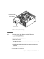
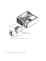
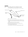
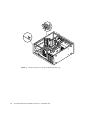
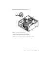
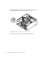
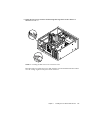
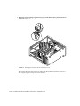
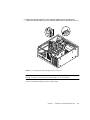
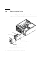
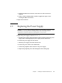
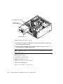
CHAPTER
1
Installing the Sun Noise Reduction
Kit
This chapter describes how to install the Sun noise reduction kit in a Sun Ultra 30 or
Sun Ultra 60 workstation. The installation procedure illustrates the procedure with
an Ultra 60 system, but installation is the same for both systems.
Installing the noise reduction kit involves the following steps.
Note – The procedures described here apply to both the Sun Ultra 30 and Ultra 60
workstations. Some steps,called out in the procedure description, are covered in
more detail in the two systems’ respective service manuals; Sun Ultra 30 Service
Manual, 802-7719, or Sun Ultra 60 Service Manual, 805-1709.
1. Removing the power supply from the system chassis.
2. Removing the Removable Media Assembly from the system chassis.
3. Installing the noise reduction kit inside the chassis
4. Routing the noise reduction kit wiring inside the chassis and making all required
connections.
5. Replacing the Removable Media Assembly into the system.
6. Replacing the power supply into the system.
1-1
1.1
Removing the Power Supply
1. Power off the system unit.
Refer to your system’s service manual.
2. Remove the side access cover.
Refer to your system’s service manual.
Caution – When removing the power supply, attach the copper end of the wrist
strap to the system unit chassis, not the power supply.
3. Disconnect the power cord from the power supply.
4. Attach the wrist strap.
Refer to your system’s service manual.
5. Remove the power supply as follows (FIGURE 1-1):
a. Using a number 2 Phillips-head screwdriver, loosen the four captive screws
securing the power supply to the chassis.
b. Slide the power supply from the chassis rear until the power supply is stopped
by the power supply cables.
c. Disconnect the peripheral cable connector from the power supply (not
illustrated).
d. Disconnect the power supply cables from the motherboard (not illustrated).
e. Remove the power supply from the chassis.
1-2
Sun Noise Reduction Kit Installation Instructions • September 1999
Peripheral power cable
Power supply
(partially extended)
Captive screw (4)
FIGURE 1-1
1.2
Removing the Power Supply
Removing the Removable Media
Assembly (RMA)
1. Remove the RMA as follows (FIGURE 1-2):
a. Remove the front bezel.
b. Using a number 2 Phillips-head screwdriver, loosen the captive screws securing
the RMA to the chassis.
c. Partially remove the RMA from the chassis.
d. Disconnect the peripheral cables and the power cables from the drives (not
illustrated).
e. Remove the RMA from the chassis.
2. Place the RMA on an antistatic mat.
Chapter 1
Installing the Sun Noise Reduction Kit
1-3
RMA
Diskette drive
CD-ROM drive
(or 4-mm or 8-mm tape drive)
Captive screw (2)
Front bezel
FIGURE 1-2
1-4
Removing the Removable Media Assembly
Sun Noise Reduction Kit Installation Instructions • September 1999
1.3
Installing the Noise Reduction Kit
The noise reduction kit consists of the following parts, as shown in FIGURE 1-3:
Fan power connector (2)
Temperature sensor
Pass-through power
connector
Wiring Routing Clip
Voltage regulator
FIGURE 1-3
Noise Reduction Kit Components
1. Insert the nylon tie wrap in the system internal chassis as shown in FIGURE 1-4.
a. Route the tie, tapered end pointing down, through two holes in the internal
chassis.
b. Slip the tapered end of the tie into the tie wrap lock.
2. Install the wiring routing clip inside the chassis, as shown in FIGURE 1-4.
a. Peel off the paper backing from the clip.
b. Press the adhesive back of the clip on to the top of the chassis as shown.
Chapter 1
Installing the Sun Noise Reduction Kit
1-5
FIGURE 1-4
1-6
Placing the Nylon Tie Wrap and Wiring Routing Clip
Sun Noise Reduction Kit Installation Instructions • September 1999
3. Attach the voltage regulator, as shown in FIGURE 1-5.
FIGURE 1-5
Attaching the Voltage Regulator
a. Slip the voltage regulator inside the tie wrap loop.
b. Tighten the tie wrap firmly to hold the voltage regulator in place.
Chapter 1
Installing the Sun Noise Reduction Kit
1-7
4. Route the temperature sensor and one of the fan power connector leads through
the wiring routing clip and inside the chassis, as shown in FIGURE 1-6.
FIGURE 1-6
Routing the Temperature Sensor and Fan Power Lead
5. Place the temperature sensor along the top of the system motherboard.
1-8
Sun Noise Reduction Kit Installation Instructions • September 1999
6. Route the fan power connector lead through the large holes in the chassis as
shown in FIGURE 1-7.
FIGURE 1-7
Routing the Rear Fan Power Connector Lead
Disconnect the rear CPU fan power cable from the system motherboard and connect
it to the voltage regulator fan power lead connector.
Chapter 1
Installing the Sun Noise Reduction Kit
1-9
7. Route the second voltage regulator fan power lead through the systems chassis as
shown in FIGURE 1-8.
FIGURE 1-8
Routing the Front Fan Power Connector Lead
Disconnect the front CPU fan power cable from the motherboard and connect it to
the voltage regulator fan power lead connector.
1-10
Sun Noise Reduction Kit Installation Instructions • September 1999
P3
P3
8. Connect the female connector of the voltage regulator power pass-through
connector to the SCSI device power connector labeled “P3” as shown in FIGURE 1-9.
FIGURE 1-9
Connecting the Pass-Through Power Connector
Note – You will connect the male connector of the voltage regulator power passthrough connector to the SCSI device in the RMA, if one is installed.
You have finished installing the noise reduction kit.
Chapter 1
Installing the Sun Noise Reduction Kit
1-11
1.4
Replacing the RMA
Caution – Use proper ESD grounding techniques when handling components. Wear
an antistatic wrist strap and use an ESD-protected mat. Store ESD-sensitive
components in antistatic bags before placing them on any surface.
RMA
Diskette drive
CD-ROM drive
(or 4-mm or 8-mm tape drive)
Captive screw (2)
Front bezel
FIGURE 1-10
Replacing the Removable Media Assembly
1. Replace the RMA as follows (FIGURE 1-10):
1-12
Sun Noise Reduction Kit Installation Instructions • September 1999
a. Position the RMA into the chassis, connect the rear cable connectors as
required.
b. Using a number 2 Phillips-head screwdriver, tighten the captive screws
securing the RMA to the chassis.
2. Replace the front bezel.
1.5
Replacing the Power Supply
Caution – Use proper ESD grounding techniques when handling components. Wear
an antistatic wrist strap and use an ESD-protected mat. Store ESD-sensitive
components in antistatic bags before placing them on any surface.
1. Replace the power supply as follows (FIGURE 1-11):
a. Feed the power supply cables through the chassis opening; support the power
supply cables while engaging the power supply into the chassis rails.
b. Position the power supply into the chassis.
c. Slide the power supply toward the chassis front.
d. Connect the power cables to the motherboard.
e. Connect the peripheral cable connector to the power supply.
f. Replace the peripheral power cable through the cable routing clips.
Chapter 1
Installing the Sun Noise Reduction Kit
1-13
Peripheral power cable
Power supply
(partially extended)
Captive screw (4)
FIGURE 1-11
Replacing the Power Supply
g. Slide the power supply toward the chassis front until the power supply rear
panel is flush with the chassis.
h. Using a number 2 Phillips-head screwdriver, tighten the captive screws
securing the power supply to the chassis.
Note – Tighten the captive screws in a clockwise order beginning with the upper
right captive screw.
2. Detach the wrist strap.
3. Connect the AC power cord.
4. Replace the side access cover.
Refer to your system’s service manual.
5. Power on the system unit.
Refer to your system’s service manual.
1-14
Sun Noise Reduction Kit Installation Instructions • September 1999