1
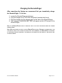
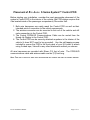
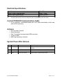
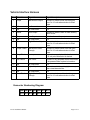
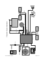
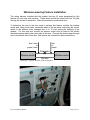
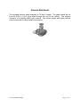
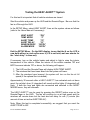
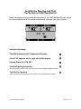
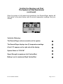
Gen 2 INSTALLATION MANUAL READ THIS FIRST Installation of this system should be carried out by qualified persons familiar with the general installation of law enforcement electronics commonly installed in police service vehicles. It is recommended that the installer(s) have updated wiring diagrams and schematics of the specific vehicle in which the system will be installed or have access to wiring information through a local dealership or other source. If you are replacing an existing deployment and/or heat alert system, remove all previous wiring before beginning installation. Our System requires that wiring connections be made as described in this manual - do not connect this to any other system’s pre-existing wires. Before installation: 1. Confirm all parts and components are included and accounted for by doing a complete inventory of the package contents. 2. Read this manual to familiarize yourself with the system’s unique requirements for installation. 3. Observe all safety practices. It is the installer’s responsibility to determine, implement, and observe those safety practices. Please note: This system is designed to be directly hardwired to the vehicle’s 12-volt battery. DO NOT CONNECT THE SYSTEM TO THE VEHICLE BATTERY UNTIL ALL CONNECTIONS HAVE BEEN COMPLETED AND VERIFIED AS BEING CORRECT. Do not connect this product to any device intended to detect vehicle battery drain. DOING SO MAY “POWER DOWN” THIS PRODUCT AND/OR RENDER IT INEFFECTIVE FOR ITS INTENDED USE. We recommend that you meet with the intended user to discuss preferences and installation requirements specific to the system’s application and user comfort. F2-G2 Installation Manual Page 2 of 17 RAY ALLEN F2 System™ Inventory External Antenna 10ft Antenna Cable Heads-Up Display (HUD) HUD Articulating Mount w/Hardware Pack (4 screws/nuts) Remote/Pager Unit Remote/Pager Holster 120V Remote Charger In-Vehicle Remote Charging Pigtail System Control POD Control POD/HUD Communications 10ft Cable (Grey) Temperature Sensor w/ 15ft cable (Grey w/Black Tip) Electrical Hardware Pack POD & HUD Attachment Hardware Pack (8 self-tapping screws) System Power Wire Harness (15ft) Vehicle Interface Wire Harness (15ft) Qty 1 Qty 1 Qty 1 Qty 1 Qty 1 Qty 2 Qty 1 Qty 1 Qty 1 Qty 1 Qty 2 Qty 1 Qty 1 Qty 1 Qty 1 Installation Manual User’s Manual (To Remain in Car) Qty 1 Qty 1 F2-G2 Installation Manual Page 3 of 17 Charging the Remote/Pager After unpacking the System we recommend that you immediately charge the Remote/Pager. To do this: 1. 2. 3. 4. Locate the Remote/Pager and charger. Plug the charger into a 120v 60hz receptacle (standard wall plug). Plug the charger into the charging port on the side of the Remote/Pager. The message CHARGING BATTERY will appear on the LCD screen of the Remote/Pager. NOTE: IF REMOTE/PAGER SEQUENCE BEGINS. THE NOTE: WE BATTERY IS COMPLETELY DEAD IT MAY TAKE A FEW MINUTES BEFORE THE CHARGING HAVE PROVIDED YOU WITH A LONG-LIFE REMOTE/PAGER BATTERY. DEPENDING ON TEMPERATURE, IT CAN FOR YOUR CONVENIENCE, THE REMOTE/PAGER IS PROTECTED TAKE OVER AN HOUR TO FULLY CHARGE THIS DEVICE. BY OVER-CHARGE CIRCUITRY THEREFORE IT CAN REMAIN ON THE CHARGER FOR LONG PERIODS OF TIME WITHOUT FEAR OF BATTERY DAMAGE. F2-G2 Installation Manual Page 4 of 17 Placement of RAY ALLEN F-Series System™ Control POD Before starting your installation, consider the most appropriate placement of the system’s Control POD in the interior of the vehicle (the POD design requires that it be located inside of the passenger compartment). Be certain that: 1. Both wire harnesses can easily reach the Control POD as well as their intended point of connection to the vehicle components. 2. The antenna connector can be mounted to the roof of the vehicle and still make connection to the Control POD. 3. The Control POD/HUD Communications Cable can be routed from the Heads-Up Display to the Control POD. 4. The Control POD can be securely attached anywhere in the interior of the vehicle (it does NOT need to be grounded). Use the self-tapping screws included to secure the POD to the front panel of your K-9 insert or attach using 2-sided tape, Velcro® or any other attachment method you choose. All wire harnesses are provided with fifteen (15) feet of wire. The POD/HUD communications cable and antenna cable are ten (10) feet long. NOTE: TAKE CARE TO ROUTE ALL WIRES AWAY FROM EXCESSIVE HEAT SOURCES AND POINTS OF POSSIBLE ABRASION. F2-G2 Installation Manual Page 5 of 17 System Specification & Features Following are the system input and output descriptions and specifications. Due to the wide variety of vehicles in which this system could be used, it is not possible to accurately describe all vehicle connections. Therefore it is up to the installer of this system to correctly locate, connect, and test each connection prior to final power connection and operational testing. Hardware Features • Reverse battery protection • Load-dump/Over-voltage protection • On-board, user-accessible fused output protection • ±0.5°C (<1°F) temperature accuracy • Direct Sequence Spread Spectrum wireless communication with belt mounted Remote/Pager o Individual encoding to ensure multiple units can be used at once o 15 selectable channels in case of interference with other equipment • Noise immune RS485 communication with Heads-Up Display (HUD) • On-board relays Heat Alert Features • Window Drop o User can select just the left, just the right, both, or neither window to roll down. o Adjustable window drop time • Fan Output o Manual and automatic control o Three speed settings or off • Alarm o User selectable horn and/or lights alarm • Programmable Auxiliary Output o Can be programmed for single/multiple pulses or continuous output o Adjustable duty cycle/pulse width F2-G2 Installation Manual Page 6 of 17 Electrical Specifications Input Voltage Supply Current (powered down) Supply Current (powered up) Remote / Pager Battery Life* 6V – 16V 50mA – 60mA 100mA - 200mA 80h - 100h * This rating assumes that remote is idling with good, consistent connection with POD. Control POD/HUD Communications Cable • A four conductor, unshielded twisted pair CAT3 cable terminated on both ends with an RJ9 crimp plug Antenna • • • • • Roof mounted, external Omni-directional Part 15 compliant reverse polarity SMA connector 10 feet of cable NMO high frequency connector System Power Wire Harness Pin # Wire Color Signal Name Signal Description 1 Red System Power Input Connect directly to positive battery terminal through included 40A fuse. 2 N/A N/A N/A 3 Blue Fan Output Connect to black fan wire to blow into cage. 4 Green System Power Ground Connect directly to negative battery terminal. F2-G2 Installation Manual Page 7 of 17 Vehicle Interface Harness Pin # Wire Color Signal Name Signal Description 1 Purple Left Window Output Connect to window motor wire that goes from 0 to 12 volts when window is rolled down. 2 N/A No Connection N/A 3 N/A No Connection N/A 4 Yellow Horn Output Connect to vehicle's horn or other auditory alarm device. 5 Grey Aux Output Multi-function auxiliary output. 6 N/A No Connection N/A 7 Blue Right Window Output Connect to window motor wire that goes from 0 to 12 volts when window is rolled down. 8 Purple / Black Left Window PassThrough Connect to window switch wire that goes from 0 to 12 volts when window is rolled down. 9 Grey / Black Aux Input Connect to any peripheral device that sends a 12 volt pulse when alert is desired. 10 Red / Black Aux Power Connect to any peripheral device that needs to be powered when system is turned on. 11 N/A No Connection N/A 12 White Lights Output Connect to vehicle's parking lights or any other visual alarm device. 13 N/A No Connection N/A 14 Blue / Black Right Window PassThrough Connect to window switch wire that goes from 0 to 12 volts when window is rolled down. Connector Numbering Diagram 14 13 12 11 10 9 7 6 5 4 3 2 8 1 Viewed from wire side F2-G2 Installation Manual Page 8 of 17 F2-G2 Installation Manual Page 9 of 17 Heads-up display Motion detector optional Temp sensor 1 Temp sensor 2 Remote / Pager Bi-directional wireless link Antenna Up Down (BL/BK) Right window switch POD 1 8 2 9 3 10 4 11 5 12 6 13 7 14 4 3 2 1 Up Down Right window motor (BL) (GY) (BK) (BL) (GY/BK) (GR) (RD/BK) (BL) (RD) Vehicle battery Fan NEG F2 System Typical Installation Up Down (YL) Horn Left window switch Up Down (PU/BK) Parking lights (WH) (PU) Left window motor POS Window Lowering Feature Installation The wiring harness included with this system has two (2) wires designated for this feature for each rear side window. These wires should be routed from the ‘B’ pillar through the conduit to each door. Make the connection inside each door. To determine the wire in the door used to activate this feature, activate the window switch and, using a volt-meter, determine which of the two wires connecting the control switch to the window motor changes from 0 to 12 volts during the lowering of the window. Cut this wire and connect the window output wire as listed in the vehicle interface harness table to the motor side of this wire. Connect the window pass-through wire to the switch side of this wire. Butt-splices are included for these connections. blue / black or purple / black blue or purple Down wire Window switch Window motor Up wire Drawing 1: Typical Window System Interface F2-G2 Installation Manual Page 10 of 17 Antenna Attachment The provided antenna cable assembly is 10 feet in length. The cable should be run from the POD to a 3/4” hole drilled through the roof of the vehicle. The antenna connector is a modified NMO style terminal. The center contact and plastic washer must be removed in order to attach the antenna. F2-G2 Installation Manual Page 11 of 17 Temperature Sensor Placement You have been provided with two (2) Temperature Sensors which are specifically designed to work with this system. Each Sensor has fifteen (15) feet of cable. These Sensors are plugged into the system Control POD (the two plugs next to the antenna port – opposite side of the wiring harnesses). Care should be taken before deciding where their final mounting point should be. We have provided hook and loop fasteners (Velcro®) to secure these Sensors. Place the cable under the Velcro® so that the black Temperature Sensor is completely exposed. Consider: 1. Neither Sensor should be mounted in a position that is subject to direct sunlight nor in close proximity to air conditioning vents or the roof of the vehicle — doing so will give incorrect readings of the “true” temperature inside the vehicle. 2. Cables should be routed to avoid points of possible abrasion. 3. Be certain the K9 cannot get to the sensors. They are not chew proof. Lights and Horn Connection Under the dashboard, at the fuse panel or under the hood of the vehicle, locate the wires used for these features. Activate the lights and the horn from inside of the vehicle. Using a volt-meter, determine the wire that changes from 0 to 12 volts when these features are activated. Carefully splice into this circuit. On certain vehicles it may be necessary to splice into the wiring circuit beyond relays and fuse boxes. MD10 F Ray Allen Fan Connection (Optional) The Ray Allen MD10 F Fan is designed to bolt directly to either side of the front panel on the Ray Allen Cruise Eze™. Hardware for this installation is included with the Fan. When attaching the Fan to the front panel of your Cruise Eze™, we suggest you insert the bolts and washers from inside of the cage and place the nut on the Fan side. You do not want the nut on the inside of the cage as it has a higher profile than the bolt head and this may injure the dog. Also included is the wiring to connect directly to the system’s Control POD. To complete this connection, attach the fan output wire from the POD to the black wire on the fan (butt-splices are included for this connection). Connect the blue wire from the fan to a positive battery voltage. Test this connection when testing the complete system. This fan is designed to blow “in” to the Cruise Eze™ unit. If for some reason you wish this fan to blow in the opposite direction, simply reverse these wire connections. F2-G2 Installation Manual Page 12 of 17 Placement of Heads Up Display (HUD) The HUD is the system's user interface used for information read-outs and feature programming therefore easy access to the HUD visually and physically is vital. We have included an articulating mount that can be used for this purpose. This mount easily attaches to the HUD using the self-tapping screws included in your hardware pack. Once the location has been determined (we recommend the intended user be involved in this decision) the base of the mount can be permanently attached to the vehicle utilizing the two-sided tape already on the base. This tape is extremely adhesive so you will only get one shot at this. If you wish to mount the HUD directly to the dashboard as shown below (photo on the right), either attach the HUD using the self-tapping screws or attach with Velcro® or two-sided tape. NOTE: TAKE CARE TO ROUTE THE COMMUNICATION CABLE AWAY FROM EXCESSIVE HEAT SOURCES OR POINTS OF POSSIBLE ABRASION. Suggested locations for the HUD: On top of dashboard. F2-G2 Installation Manual On facing of dashboard. Page 13 of 17 Completing the Installation Verify the following before proceeding: • All connections except the four-conductor, black system power connector are securely attached to the Control POD. • The other end of the gray data cable is connected to the HUD. • All wire splices and butt connectors are secure and that there is no chance of a short circuit. Once all of the above is completed, connect the System’s Power and Ground cables to the vehicle battery’s positive and negative terminals and plug the fourconductor, black system power connector into the POD. Power up the RAY ALLEN F-Series System™ by pressing and holding down the center button on the front of the HUD. When the display appears, release the button. The HUD will run a self diagnostic routine. Upon completion of this routine proceed to the following steps. F2-G2 Installation Manual Page 14 of 17 Testing the HEAT ALERT™ System For this test it is important that all vehicle windows are closed. Start the vehicle and power up the HUD and the Remote/Pager. Be sure that the fan is off through the HUD. In the SETUP Menu, select HEAT ALERT, then set the system values as follows (refer to the Users Manual if necessary): HEAT ALERT TEMP MODE ALERT TEMP ALERT DELAY WINDOW DROP ALARM MODE “ON” “F” “70” “01” “BOTH” “BOTH” Exit the SETUP Menu. On the HUD display, insure that the H on the LCD is now bold without a circle w/line over it (if it is not bold, wait one minute for the “alert delay” to time-out). If necessary, turn on the vehicle heater and adjust to high to raise the interior temperature of the vehicle. When the interior of the vehicle reaches 70F and BOTH sensors indicate 70F or above, the following will happen: 1. The HUD and the Remote/Pager will display HIGH TEMP ALERT. 2. The windows that have been wired into the system will lower. 3. After the windows have lowered, the system will turn on the fan at full speed (if the optional fan is installed). Approximately 30 seconds after a HEAT ALERT™ has activated and not been reset, the vehicle’s horn (if integrated) will sound and the lights (if integrated) will flash. If both the horn and lights are connected and selected in the ALERT MODES menu, they will alternate. The HEAT ALERT™ can be reset by pressing the RESET button once on the Remote/Pager or the HUD. The fan will continue to run at high speed and the windows will remain down but the heat alert will delay for one (1) minute (the amount of time set as the ALERT DELAY). Note: When this test is completed successfully, we suggest that you reset the ALERT TEMP to 85F. F2-G2 Installation Manual Page 15 of 17 Confirm the Displays and That The System is Fully Operational Once the system is fully tested and operational, the HUD display will look similar to the photo below (with the actual temperature readings from your vehicle). Verify the following: The HUD shows two (2) Temperature Displays A bold “H” appears on the right side of the display System Status is “SYS OK” Test the Back-light function (Do so by pushing the left button on the HUD to cycle through the brightness levels. Test the Fan function (Do so by pushing the right button on the HUD to cycle through the fan speeds. F2-G2 Installation Manual Page 16 of 17 Confirm the Displays and That The System is Fully Operational (continued) Once the system is fully tested and operational, the Remote/Pager display will look similar to the photo below (with the actual temperature readings from your vehicle). Verify the Following: The Remote/Pager makes connection w/ the system The Remote/Pager displays two (2) temperature readings A bold “H” appears on the right side of the display System Status is “SYS OK” Signal Strength is maximum (Left Vertical Bar) Battery Level is maximum (Right Vertical Bar) F2-G2 Installation Manual Page 17 of 17