1
Installation Instructions
®
“Big Twin ” Camshaft
For 1948-1965 “Panhead®” Engines And
1965-1984 “Shovelhead®” Engines
For more information, see www.cranecams.com
These instructions are a guide to assist in the
installation of your new Crane camshaft in your
"Big Twin®" Harley-Davidson®. This instruction
guide is not designed to perform as a complete
service manual. If you are not sure about
dimensions, torques, timing setting, etc. not
included in this material, refer to your service
manual for your model of motorcycle.
It is important to remember that the concept of
a "bolt-in" camshaft with no inspection from the
engine builder does not really exist. It is the
engine builder's responsibility to be sure that
the component parts that he is using will be
compatible with one another and provide proper running clearance. It is generally accepted
that camshafts with valve lifts greater than
.455" may require modifications to either the
valve spring assembly, valve guides, valves,
and/or pistons to provide proper clearance.
The increase in lift may be itself not cause a
problem, but is used with other components
(such as new "thick margin" valves with new
valve seats in the head) in combination may not
provide the clearance necessary. Mocking up
of the parts with careful inspection is always
advised. For example, some engines may
require that the crankcase be ground in order to
clear the innermost lobe on a high lift camshaft.
If you feel that you do not have the knowledge
or experience for this inspection and possible
modification of component parts, then seek
assistance from a qualified dealer.
may have point ignition.)
4. Remove the gear case cover screws and
remove cover and gasket (Fig. 9).
5. Remove tappet guide screws and lift out
tappet guide assemblies. Be careful not to
drop the tappets out of the bottom of
guides (Fig. 10 & 11).
6. Remove camshaft assembly, spacing
washer, and thrust washer (Fig.12). Save
the spacing washer and thrust washer for
re-assembly on new camshaft.
IMPORTANT NOTES FOR 1948
THROUGH 1969 MODEL ENGINES
Fig. 1
Fig. 2
REMOVING THE OLD CAMSHAFT ALL MODELS
1. Disconnect the battery. Secure the motorcycle on a suitable stand with the rear
wheel off the ground if no kickstarter is on
the model. Remove components necessary for easy access to pushrod covers an
gear case cover, i.e., exhaust system (Fig.
1), right footrest (Fig. 2) brake pedal (Fig.
3), and air cleaner.
2. Remove pushrod cover keepers and lift
covers (Fig. 4 & 5). Remove spark plugs
and rotate engine with kicker, or by moving
rear wheel with motorcycle in gear. Turn
engine until both valves are closed on the
front cylinder. This is found when you can
see both front cylinder tappets in the down
position and see the piston at the top
through the spark plug hole. Loosen the
locknuts on each pushrod adjuster and
adjust shorter until pushrod can be lifted
out (Fig. 6). Repeat this same procedure
Fig. 3
for the rear cylinder. (Keep pushrods in
order for re-assembly.)
3. Remove ignition cover on gear case cover.
(Drilling out of two rivets may be necessary.) Remove adjusting plate. Remove
bolt and rotor. (Figs. 7 & 8 - Your model
1. The 1948 through 1957 engines used a
"bushing" in the crankcase to align the
camshaft in position. The 1958 and later
engines used a "needle bearing". All
Crane camshafts are ground for the needle-bearing dimension and can not be
used with a bushing. If your engine has
the crankcase bushing, it must be converted to the needle bearing by a qualified
dealer.
2. The earlier model engines (1948 through
1969) drive the ignition system by use of a
series of gears. These engines require a
camshaft with a short nose (approximately 3/4" long). The "circuit breaker" gear is
positioned very close to the front lobe of
the camshaft. It is possible that this gear
can hit the lobe of a high lift camshaft. You
must inspect the clearance between the
lobe and the circuit breaker gear to be
sure it's at least .030" or more. If not, this
gear must be removed and modified in a
lathe to provide the proper clearance. In a
lathe, the teeth can be machined down
and narrowed only in the area where the
lobe is hitting, in order to allow for the necessary clearance, and still keep enough
width for the gear to drive the ignition system. The 1970 and later engines drove
the ignition off the end of the camshaft and
used a long nose (approximately 1 5/16"
long) camshaft.
IMPORTANT NOTE CONCERNING
CAMSHAFT GEARS
Harley-Davidson® used two different style cam
gears in the engines between 1948 through
1984. These gears (and matching pinion and
breather gears) are NOT INTERCHANGEABLE. You must be sure that your cam gear is
CRANE CAMS, INC. 530 Fentress Blvd., Daytona Beach, FL 32114
www.cranecams.com Tech Line: (904) 258-6174 Fax: (904) 258-6167
4/00
1
327E
Fig. 4
marks required by Harley-Davidson®. Its
matching pinion gear has teeth across the full
width of the pinion gear body. The matching
breather gear has a "slash mark" (l) to identify
its timing position.
The late 1977 through 1984 (non-Evolution®)
engines used a cam gear with a "curved tooth".
This gear is identified by a "groove" cut into the
face of the gear. The matching pinion gear had
teeth across only half of the width of the pinion
gear body. The matching breather gear had a
"cross" (+) to identify its timing position.
SETTING GEAR LASH
Fig. 5
Fig. 6
In order to establish the proper gear lash, cam
gears and pinion gears are made in different
pitch diameters. The different sizes of gears
are identified by "color codes" on both gears.
(Check the color code chart in your HarleyDavidson® manual for the exact sizes.) It is
advisable to match the color code of the cam
gear (if available) to the color code of the original pinion gear. Crane offers three cam gear
sizes which are .001" difference in pitch diameter. They are identified as color code "yellow"
(smaller size), "red" (medium size), and "blue"
(larger size). If the gears are not matched properly, you may witness some gear noise. If the
gears are too loose, you will hear a "gear clatter" (much like a lifter noise), if the gears are
too tight, you will hear a gear "whine". When
the gears are properly fitted, you will hear a
very slight gear whine when the engine is hot.
You can also fine tune the gear lash by changing the stock pinion gear to the next size larger,
or smaller, as necessary.
ADJUSTABLE CAM GEAR.
Fig. 7
properly mated to the other components for
compatibility.
The 1948 through early 1977 engines use a
cam gear with a "straight cut tooth". This gear
is plain in appearance with no identification
4/00
Crane offers many of its camshafts with multiindex cam gears. This allows you to install the
cam in either the original "straight up" zero
degree ("0") position, 4 degrees advanced
("A"), or 4 degrees retarded ("R"). Advance the
cam pulls the power range down a few hundred
RPM, creating better bottom-end power.
Retarding the cam raises the power band up,
creating better top-end power. A small arbor
press and a simple holding fixture will be
required to remove the gear and to relocate it to
your desired keyway position.
NOTE: When the gear is off the camshaft,
double check the keyways for burrs or raised
areas. Deburr keyways and lightly hand finish
face of gear with fine emery cloth on a flat surface.
2
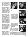
CHECKING FOR "VALVE TO VALVE"
CLEARANCE
The design of the Harley-Davidson® hemispherical cylinder head, with its existing valve
angles, can cause the edge of the intake and
exhaust valves to touch one another during the
"overlap period" on certain camshafts. You
must check to be sure that the valves are not
touching.
There are many sophisticated tools and methods for checking this clearance, but what we
will describe here is the basic way.
Since the valve spring tension could cause a
hydraulic tappet to "bleed down" during the
test, and give you a false reading, we recommend using "solid tappets" when performing
this inspection. If you do not have solid tappets
available, then you must disassemble your
hydraulic tappets, drain the oil, and clean them.
Replace the tappets in the guide and lengthen
the pushrods to the full extent of the hydraulic
tappet's plunger travel. With the hydraulic tappet completely compressed, it will act as a solid
tappet and allow you to do the test properly.
You must make yourself a tool out of .030"
diameter wire then put a 90-degree bend
approximately 3/8" long on any convenient
length of wire. Now rotate the engine so the
piston is at T.D.C. during the "overlap period".
(This is when the exhaust valve is closing and
the intake valve is opening, and both valves are
off the seat at the same time.) We want to
check to be sure there is at least .030" clearance between the valves as they pass by one
another. Put the checking wire through the
spark plug hole and position it between the
valves. Use a flashlight to shine into either the
intake or exhaust port, while looking into the
other port. If the wire will not pass between the
valves, the valves and/or the valve seats must
be modified to provide this clearance.
If necessary, the valves can be modified by
reducing their head diameter, or by machining
a 45-degree angle on the portion of the valve
head that faces into the combustion chamber.
If this does not correct the situation, then the
valve seats in the heads will need to be ground
deeper. This will "sink" the valves into the
heads providing extra clearance at overlap.
CHECKING "VALVE TO PISTON"
CLEARANCE
There must be at least .080" clearance
between the valve and piston.
327E
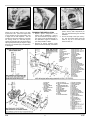
GENERAL INSTRUCTIONS
1. Install spacing washer and thrust washer
on camshaft (Fig. 13). Install camshaft.
Check to make sure the innermost lobe
clears the engine case (Fig. 14). If not,
clearance must be made by removing
case material with a cutter or grinding
wheel. Care must be taken to keep chips,
or grindings, out of the cam bearing. The
inside of the gear case must be thoroughly cleaned after any grinding process.
2. Camshaft must be installed with the timing
marks lined up on both the pinion gear
and the breather gear. To install in a 4degree advance, or a 4-degree retard
position, the gear must be pressed off of
the camshaft and key lined up with the
respective mark. The camshaft is then
pressed back into the gear, Make sure the
camshaft is lined up straight during the
pressing operation. Use of an arbor press
is recommended. The timing marks on the
camshaft gear are then lined up with the
marks on the pinion and breather gears.
3. Camshaft end play must be checked at
this point. With camshaft and original
thrust washers installed in the crankcase,
install the gear case cover with a gasket
and tighten down the screws. Reach
through the tappet guide hole (Fig. 15)
and slide the camshaft back and forth.
There should be a "slight drag" indicating
proper fit of the nose of the cam and the
bushing in the gear case cover. Try to
rotate the camshaft to see if there is too
much lash in the cam and pinion gears.
(See "setting gear lash" section.) If you
have a dial indicator available, measure
the amount of movement (end play) at the
nose of the camshaft as you slide it back
and forth in the case. If no indicator is
available, insert a feeler gauge between
the hardened thrust washer and the thrust
face of the camshaft. (Do NOT measure
between the case itself and the thrust
washer.) Depending on the year of the
engine, the end play can be between .001"
to .016", with an ideal situation of .003" to
.005". If using a point-type ignition system, you must maintain the cam end play
between .003 to .008". To arrive at the
proper end play, different thickness spacing washers are available from a HarleyDavidson® dealer. Also, be sure the thrust
washer is installed properly with the "ears"
facing down and the cutoff portion of the
washer towards the rear cylinder.
SETTING PRELOAD USING STOCK
HYDRAULIC TAPPETS AND
PUSHRODS
1. Remove tappets from guide, drain oil and
clean one at a time, then reassemble.
Replace tappets in guide with "oil hole
flats" (on the side of the tappet body) facing towards the center of the guide block.
Install guides into case, being careful not
to drop the tappets into the gear case.
Install new tappet block gasket, and for
engine models 1977 and later, use an
aligning tool (Crane part #9-0021 or
4/00
Fig. 8
#H.D.-33443) to position the tappet guide
block in the case, and tighten all the
screws.
2. The engine must be rotated so that the
tappet you are adjusting is riding on the
"heel" of the cam lobe (no lift involved). To
determine this, you will watch the same
valve (intake or exhaust) on the opposite
cylinder (the cylinder opposite the one
you're working on). If the same valve on
the opposite cylinder is at full lift (tappet all
the way up in the guide block), then the
one you're adjusting will be all the way
down and riding on the "heel" of the lobe.
For example: When the exhaust tappet on
the rear cylinder is at full lift (all the way up
in the guide block), you will then adjust the
exhaust tappet on the front cylinder, which
will be all the way down. Do one tappet at
a time to avoid confusion.
3. Install the pushrod and adjust. (Be sure to
use new gaskets and seals on the
pushrod tubes.)
REMEMBER, THE
STOCK TAPPETS MUST BE CLEAN AND
DRAINED OF OIL TO DO THE ADJUSTING PROCEDURE. Turn one pushrod
adjusting screw down until the hydraulic
unit is completely compressed. Then turn
it back up 1 & 1/2 turns (nine flats on the
adjusting hex). Lock it in place by tightening the locknut. An adjusting gauge (part
#HD-94438-79) could be used at this point
to double check the tappet adjustment.
4. Follow this procedure of rotating the
engine and adjusting the tappets until all
four are adjusted properly.
5. Extend pushrod tubes and insert keepers
in place.
Note: Improper lifter preload is probably the
most common cause of hydraulic tappet noise.
Different manufacturers of hydraulic tappets
may have their own method for arriving at the
desired "reload" for their particular tappet
design. Therefore, you must follow the methods that the manufacturer of your tappets recommends.
Fig. 9
Fig. 10
Fig. 11
Fig. 12
SOLID LIFTERS
Follow the procedures already described in the
preceding sections, but naturally since you will
be using a "solid tappet", there will be no oil in
the tappet to drain, and no pre-loading.
Instead, you will run a slight amount of clearance between the tappet and pushrod.
3
When the engine is properly rotated so that the
tappet is riding on the heel of the cam, lengthen the adjusting end of the pushrod until the
slack is taken up. When the engine is cold, you
should be able to spin the pushrod with your
327E
Fig. 13
fingers, but not be able to move it up or down
by more than .002". (When the engine heats
up the cylinders will grow approximately .040"
in length, due to heat expansion. This will
increase the valve lash clearance, and create
the "ticking" sound of a solid lifter engine.)
Tighten the pushrod locking nut and recheck by
spinning the pushrod with your fingers. A slight
drag, but no up and down play, is acceptable on
a cold engine
4/00
Fig. 14
FINISHING THE INSTALLATION
1. Replace ignition components in the
reverse order of disassembly. Refer to
your service manual for proper setting. If
your ignition cover was fastened with rivets, replacement rivets are available at
your Harley-Davidson® dealer.
2. Reinstall air cleaner assembly, brake
pedal and footrest assembly, the exhaust
4
Fig. 15
system, and any other components you
may have removed during the camshaft
installation.
3. You are now ready to start your motorcycle. Run the engine before riding and
check for any oil or fuel leaks, loose
screws or bolts, etc.
327E