1
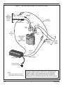
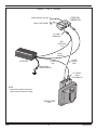
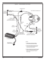
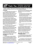
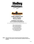
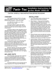
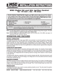
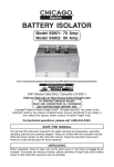
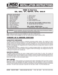
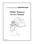
INSTALLATION INSTRUCTIONS for
HI-6S PERFORMANCE
IGNITION SYSTEM
Part Number 6000-6300
CAUTION: READ INSTRUCTIONS CAREFULLY BEFORE STARTING INSTALLATION
OVERVIEW - READ FIRST!!
The optional HI-6TR Timing Retard Control (P/N 6000-6470)
adds 0-20 degrees adjustable retard. A boost sensor can be
added to give 0-4 degrees per psi boost proportional retard. Refer
to page 18.
Before proceeding with the HI-6S installation, read the introductory material below and on pages 2-4. Then use the
Applications Index to find the appropriate section for your vehicle.
INTELLIGENT MULTI-SPARK
INTRODUCTION
Multi-spark is generated by repeatedly turning the coil current
on and off during the spark sequence. At low RPM, during cranking, the HI-6S generates upwards of 12 sparks. This assures quick
starting even under the most adverse conditions. At idle and
cruise, the number of sparks fired is adjusted to maintain a total
spark duration of about 20 degrees (crankshaft), assuring smooth
idle, improved throttle response, and eliminating the lean surge
characteristic of some late model emission controlled vehicles.
During acceleration at higher RPM levels, the HI-6S generates a
single powerful spark with about twice the spark gap energy of
O.E. systems (with use of recommended LX-91 or PS-91 coil).
The Crane HI-6S part number 6000-6300 is a multi-spark
inductive ignition specially optimized for street driven performance
vehicles with an engine redline below 8,000 RPM. A RISC microcontroller manages all functions of the HI-6S including the two
stage rev limiter and timing retard capability. The lower stage of
the rev limiter can also be used as an anti-theft function by using
a switch hidden under the dash to select a very low rev limit that
keeps the engine from running above idle (details on page 12).
The HI-6S is intended for use with vehicles equipped with
original equipment (O.E.) electronic ignition and computer engine
control. Crane LX91 or PS-91 coils are recommended for optimum
performance, however the HI-6S is compatible with most O.E.
coils. Some late model vehicles with fuel injection or OBD II On
Board Diagnostic system may require Crane P/N 6000-8950
Universal Trigger adapter when installing the HI-6S. The HI-6S is
not compatible with distributorless ignitions. The HI-6S is 50 states
legal (California Air Resources Board E.O. D-225-59) for vehicles
without OBD II.
SEQUENCE REV LIMITER
The HI-6S has a built in two stage rev limiter that can be set
via rotary trimpots from 1,000 to 5,000 RPM for the stage rev limit
and 4,000 to 8,000 RPM for the maximum rev limit.
The HI-6S utilizes a sequential firing program to equalize
cylinder firing at the rev limit. When engine RPM exceeds the rev
limit, firing stops. The HI-6S counts the number of cylinder firings
that are skipped. Once RPM drops below the rev limit, firing is
resumed when the count reaches an odd number. If the engine is
held against the rev limit, RPM will stay within a narrow band. All
cylinders will be fired equally in rotation. Fuel loading and plug
fouling will be greatly reduced. For most V6 and V8 engines, cylinders will fire in alternate banks. This helps to minimize harmonics
and vibrations that can stress engine and drivetrain parts.
APPLICATIONS INDEX
All except Honda and OBD II . . . . . . . . . . . . . . .Page 4
(most 1981 and up vehicles with O.E. electronic
ignition and engine control computer, and 197286 Mopar with 4 or 5 pin module)
DIAGNOSTICS
Honda and Acura Integra . . . . . . . . . . . . . . . . . Page 5
(with O.E. electronic ignition and external or
internal coil)
A status LED is provided to assist in basic troubleshooting.
When the ignition switch is turned on, the HI-6S completes an
internal diagnostic check and lights up the status LED. When the
engine is cranked, the status LED will blink to indicate that a valid
trigger signal is being received.
All vehicles with OBD II Diagnostics . . . . . . . .Page 12
(hookup with Universal Trigger adapter. Also use
for problem vehicles where fuel injection or tach
will not function properly after HI-6S installation)
SPARK PLUGS AND WIRES
Do not use solid copper core spark plug wires, or non-resistor spark plugs with the HI-6S, as this can generate electrical
530 Fentress Boulevard, Daytona Beach, FL 32114
Tech Line: (386) 258-6174
Fax: (386) 258-6167
Check our web site for updates: www.cranecams.com
3/99
1
9000-6300A
noise that may interfere with the HI-6S or other on-board computer and radio equipment.
Ground hookup. Connect the heavy black HI-6S wire directly to
chassis ground. Use the supplied 3/8” ring terminal.
The use of O.E. high resistance carbon or suppression spark
plug wires is not recommended, as this will cause a significant loss
of spark energy. For optimum results, use low resistance spark
plug wires, such as Crane FireWire spiral core. Wire resistance
should be 300-900 ohms per foot.
+12 volt hookup. Connect the red HI-6S wire to switched +12 volt
power. In most applications, switched +12 volt power is available at
the Coil+ terminal. Refer to your vehicle wiring diagram. If you are
unsure which terminal is Coil+, use the following procedure. Label
and then disconnect O.E. wires from the coil. Turn the ignition
switch on. Use a 12 volt test light or voltmeter. The wire from the
ignition switch to Coil+ will be hot.
Resistor spark plugs are required for all applications unless
recommended otherwise by vehicle manufacturer. Use manufacturer’s recommended plug gap.
Ballast resistance. Some vehicles (such as Ford with Duraspark
ignition and early Chrysler with 4 or 5 pin electronic ignition modules) use ballast resistance. This can be in the form of a ballast
resistor or resistance wire between the ignition switch and Coil+
terminal. For proper operation of the HI-6S, ballast resistance must
be bypassed. Locate the ballast resistor or resistance wire (refer to
your vehicle service manual). Bypass it with heavy 14 or 16 AWG
stranded wire. If this is not practical, you can add an ignition power
relay using the hookup shown in Figure 13.
COIL COMPATIBILITY
WARNING: High voltage is present at the
coil primary and secondary terminals. Do
not touch the coil while the engine is
running. Do not connect any test equipment to the coil.
If you are unsure whether or not your vehicle has ballast resistance, measure the voltage at the Coil+ terminal while the engine
is idling. If the Coil+ voltage is less than 11 volts, your vehicle probably has ballast resistance that must be bypassed.
Most O.E. coils used on late model vehicles with electronic
ignition are compatible with the HI-6S. Maximum recommended
primary resistance is .6 ohms. Optimum results, and a significant
increase in spark energy will be obtained by using the Crane LX91 or PS-91 coil. The HI-6S is specially tuned for use with Crane
LX-91/PS91 coils.
Coil. Remove all O.E. wires from Coil- terminal. These O.E. wires
will be connected to the HI-6S in the next step. Connect the yellow
HI-6S wire to the Coil- terminal.
Trigger. Connect the white HI-6S wire to all O.E. wires that were
removed from the Coil- terminal above. The white wire is the trigger input to the HI-6S. It requires a 12 volt signal, such as that from
the output of an O.E. ignition module. This type of trigger signal is
sometimes referred to as a “module” or ”points” trigger signal.
Note: the HI-6S cannot be triggered directly from a Hall Effect or
magnetic pickup.
INSTALLATION
A parts bag with hardware and electrical terminals is provided for your convenience. All connections must be made with
stranded copper wire. Crimp terminals are recommended over soldering, which can make wires brittle near the solder joint. Make
sure all terminals are clean and free of corrosion. Scrape off paint,
dirt, and grease when making connections to ground. You will
require common hand tools including a proper wire stripping and
crimping tool. Do not attempt to use pliers to crimp terminals.
Tach. In most cases the O.E. connections to the tach (and possibly fuel injection system) are made to the Coil- terminal.
Sometimes these connections are within the wire harness and are
not brought out to Coil- as separate wires. If you connected all O.E.
wires that went to Coil- to the white HI-6S trigger wire as instructed above, your tach and fuel injection should continue to function.
If not, you may have to use the Crane Universal Trigger accessory as described on page 12 and the hookup shown in Figure 11.
MOUNTING THE HI-6S UNIT
The HI-6S is fully encapsulated and capable of withstanding
high temperatures and water splash.. However salt spray and corrosive cleaning agents may in time attack the anodized finish. For
this reason, Crane recommends mounting the unit in the passenger compartment if possible.
Cylinder Select. The blue HI-6S wire is used to program the rev
limiter and retard feature for the correct number of cylinders. Refer
to Figure 2. For 8 cylinder engines, tape up the blue wire. For 4
cylinder engines, connect the blue wire to the red switched +12
volt wire with a 3M splice. For 6 cylinder engines, connect the blue
wire to ground with a 1/4” ring terminal.
Make sure that the HI-6S mounting location is away from
exhaust system heat, protected from salt water splash, and has
good airflow for cooling. When you have picked a mounting location, make sure that the wire harness will reach and that the rev
limiter trimpots are accessible. Use the supplied sheet metal
screws for mounting. At least two screws should be used to secure
the unit.
Stage Limit. The orange HI-6S wire can be connected to a normally open switch to select the stage rev limit as shown in Figure
3. +12 volts applied to the orange wire selects the stage rev limit.
If the orange wire is left open or grounded, the maximum rev limit
is active. Tape up this wire if it is not used. In some applications,
the stage input is connected to a switch that also controls a line
lock or transmission brake solenoid valve. When the switch opens
and current flow to the solenoid is interrupted, electrical transients
BASIC HOOKUP
This section explains the basic hookup of the HI-6S, as shown
in Figures 1-3. You can use this hookup for applications not specifically referenced in the Applications Index.
3/99
2
9000-6300A
Figure 1. Basic Hookup
START
BALLAST
RESISTOR
RUN
IGNITION
SWITCH
3M WIRE SPLICE
+12V
–
ADD JUMPER
ACROSS BALLAST
RESISTOR
+
12 VOLT
BATTERY
+
RED
SWITCHED
+12V
GROUND
–
COIL
YELLOW COIL -
M F
WHITE
TRIGGER
HI-6S UNIT
HEAVY BLACK
CHASSIS GROUND
M
F
NOTES:
TYPICAL
1/4" MALE-FEMALE
QUICK DISCONNECTS
1. Cylinder select, stage limit, and
retard input connections not shown
for clarity.
2. Some early models including Ford
and Chrysler use ballast resistor or
resistance wire. Add jumper to bypass
ballast resistance.
RPMX100
O.E. WIRE
TO COIL -
3. Any condenser connected to O.E.
Coil- wire must be disconnected and
removed.
4. Crane LX91 coil recommended for
maximum performance.
TACHOMETER
O. E.
ELECTRONIC
IGNITION
MODULE
CUT WIRE
AND REMOVE
CONDENSER
IF NECESSARY
CONDENSER
3/99
3
9000-6300A
Figure 2. Cylinder Select Hookup
3M WIRE SPLICE
+12V
FROM
IGNITION
SWITCH
RED
SWITCHED
+12V
4 CYLINDER
CONNECT TO +12V
HI-6S UNIT
BLUE
CYLINDER SELECT
8 CYLINDER
TAPE UP
6 CYLINDER
CONNECT TO GROUND
and distributor with vacuum advance). These GM HEI systems
with vacuum advance require triggering directly from the magnetic pickup. Use the Crane HI-6 CD system for these GM HEI applications.
(up to 500 volts) occur. These transients can lead to glitches in onboard electronics. The solution is to install the supplied surge
absorber. It will limit the maximum voltage to about 40 volts. The
surge absorber appears as a small 1/2 inch diameter disk with two
wire leads. Solder one lead to the stage switch and the other lead
to a terminal that connects to ground as shown in Figure 3.
The HI-6S will be triggered from the output of the O.E. electronic ignition module. Before starting, identify all O.E. wires to the
ignition coil. Use the hookups shown in Figures 5-9 for common
Ford and GM applications. Refer to Figure 1 for all other applications. Hookup is as follows:
Retard Input. The brown HI-6S wire can be connected to a 1
Kohm (1000 ohms) potentiometer and normally open switch as
shown in Figure 3 or to the optional HI-6TR Timing Retard Control.
If you plan to add this optional module, please read the material
starting on page 18 for more details.
1. Connect black HI-6S ground wire to a good chassis
ground.
2. Identify Coil+ and Coil- terminals. If your vehicle has
ballast resistance, bypass or install the power relay circuit.
CAUTION: If the retard feature is not
used, you must connect the brown
wire to switched +12 volt as shown,
or the timing will always be retarded
20 degrees.
3. Refer to the previous section for details. Connect the
red HI-6S switched +12 volt wire to the Coil+ terminal.
4. Remove O.E. wire(s) from Coil- terminal. Tie all these
wires together and connect them to the white HI-6S
trigger wire.
If the basic connection with a potentiometer and switch is
used, up to 20 degrees of retard can be commanded when the
switch is closed. The potentiometer should be a 1 Kohm minimum
2 watt unit with a “linear” (not audio) taper, such as a Clarostat
RV4LAYSA102A available from Digi-Key Electronics (1-800-3444539).
5. Connect the yellow HI-6S Coil- wire to the Coil- terminal. There should not be any other wires connected to
Coil-.
6. Tach and fuel injection. In some cases, the trigger
wires for tach and fuel injection will be connected to the
O.E. module output somewhere within the vehicle wire
harness and will not be brought out to Coil- as separate
wires. Usually these systems will continue to function
properly. If the tach or fuel injection doesn’t work, you
may have to use the Universal Trigger adapter
described on page 12.
HOOKUP INSTRUCTIONS FOR
SPECIFIC APPLICATIONS
LATE MODEL VEHICLES WITH O.E.
ELECTRONIC IGNITION
7. Some O.E. systems may have a condenser at the coil
or near the ignition module. Disconnect and remove
the condenser.
Use this hookup for most late model vehicles with O.E. electronic ignition. Note that the HI-6S cannot be used with GM vehicles with 4 or 5 pin HEI modules (typically 1974-1980 model years
3/99
4
9000-6300A
Figure 3. Stage Limit and Retard Hookup
SWITCHED
+12V
0 20
1K POT
RETARD
ADJUST
CAUTION: IF RETARD INPUT
NOT USED, CONNECT BROWN
WIRE TO SWITCHED +12V
NORMALLY OPEN
RETARD SWITCH
BROWN
RETARD
INPUT
TARD
RE
HI-6TR
OPTIONAL HI-6TR
RETARD
CONTROLLER
ORANGE STAGE
LIMIT INPUT (TAPE UP IF NOT USED)
HI-6S UNIT
SWITCHED
+12V
NORMALLY OPEN
STAGE LIMIT SWITCH
GROUND
GROUND
LINE LOCK OR TRANSMISSION
BRAKE SOLENOID VALVE
INSTALL SUPPLIED SURGE
ABSORBER IF SOLENOID
VALVE IS USED
Detailed instructions are given in the following sections.
8. Connect the blue HI-6S cylinder select wire as required
for your engine. Connect the orange HI-6S stage rev
limit and brown HI-6S retard input wires as required.
HONDA EXTERNAL COIL HOOKUP
1. Refer to Figure 9. Connect black HI-6S ground wire to
a good chassis ground.
VEHICLES WITH HALL EFFECT
SYSTEMS
2. Identify the two plugs on the Honda/Acura O.E. coil.
Connect the HI-6S as shown. Use terminals and wire
supplied in the parts bag. Note that some O.E. coils
have only a single plug. Identify wires and connect similar to Figure 10. Most vehicles use blue color code for
module output and tach connection to Coil- terminal
and black-yellow color code for switched +12 volt
power connection to Coil+ terminal. Connect all blue
wires from O.E. harness to white HI-6S trigger wire.
Connect yellow HI-6S Coil- wire to Coil- terminal.
Connect red HI-6S switched +12 volt wire to Coil+ terminal and all O.E. black-yellow wires.
Many late model vehicles, especially European vehicles, have
O.E. Hall Effect ignition systems. Use the output of the O.E. electronic ignition to trigger the white HI-6S wire as shown in Figure 1.
The Hall Effect pickup cannot directly trigger the HI-6S.
1972-86 MOPAR VEHICLES WITH 4
OR 5 PIN MODULES
Use the output of the Mopar 4 or 5 pin module to trigger the
white HI-6S wire as shown in Figure 1. All these vehicles have a
ceramic ballast resistor mounted on the firewall. Four pin modules
use a two terminal ballast resistor. You can bypass this resistor by
soldering all the wires going to it together. Five pin modules use a
four terminal ballast resistor. The ballast resistor also supplies
power to the five pin module. Bypassing the resistor may damage
the module. You must use the power relay circuit shown in Figure
13 if your vehicle has a five pin module.
3. Tach and fuel injection. Usually these systems will continue to function properly if left connected as is. If the
tach or fuel injection doesn’t work, please call Crane
Tech Support.
4. Connect the blue HI-6S cylinder select wire to the red
+12 volt wire as shown in Figure 2 (for 4 cylinder
engine). Connect the orange HI-6S stage rev limit and
brown HI-6S retard input wires as required.
HONDA AND ACURA INTEGRA
Late model Honda and Acura Integra have either a distributor
with internal coil or an external coil. The O.E. internal coil is not
suitable for use with the HI-6S and must be replaced with a Crane
PS91. Internal coil distributors can easily be converted to external
coil by changing the distributor cap.
3/99
5
9000-6300A
Figure 4. GM Internal HEI Distributor Hookup
IMPORTANT!
FOLLOW SEQUENCE
FOR WIRES
NOTES:
1. Use this hookup only for distributors
without vacuum advance. HI-6S not compatible
with GM 4 or 5 pin ignition modules used in
vacuum advance distributors.
1/4" FEMALE
QUICK
DISCONNECTS
2. Cylinder select, stage limit and retard
input connections not shown for clarity.
GM HEAVY
RED OR PINK
SWITCHED
+12V
YELLOW
COIL -
HI-6S UNIT
RED
SWITCHED
+12V
HEAVY BLACK
CHASSIS GROUND
12" RED
JUMPER WIRE
12" BLACK
JUMPER WIRE
WHITE
TRIGGER
GM TACH WIRE
(REMOVED FROM
HEI CAP)
USE 1/4" MALE
TERMINAL
SHORT LENGTH
OF WHITE WIRE
USE 1/4" MALE
TERMINALS
WARNING:
GM COIL MUST BE GROUNDED
WITH BLACK JUMPER WIRE
AS SHOWN.
TO
GM
MODULE
3/99
BROWN
BLACK
PINK
6
9000-6300A
Figure 5. GM Early Model External HEI Distributor Hookup
GM
COIL
CONNECTOR
GM
O.E. WIRE
HRNESS
1/4" MALE
TERMINALS
JUMPER WIRES
ACROSS AS SHOWN
WHITE
TRIGGER
RED
SWITCHED
+12V
12" RED
JUMPER WIRE
HI-6S UNIT
YELLOW
COIL HEAVY BLACK
CHASSIS GROUND
F
1/4" FEMALE
QUICK
DISCONNECTS
F
NOTES:
GM
EARLY HEI
COIL
1. Use this hookup only for distributors
without vacuum advance. HI-6S not compatible
with GM 4 or 5 pin ignition modules used in
vacuum advance distributors.
2. Cylinder select, stage limit and retard
input connections not shown for clarity.
3/99
7
9000-6300A
Figure 6. GM Late Model External HEI Distributor Hookup
M
F
GM O.E.
HARNESS TO
TACH AND
IGNITION
SWITCH
TACH
WHITE
CUT AND
TAPE UP
SWITCHED +12V
PINK
12" WHITE
JUMPER WIRE
3M WIRE SPLICE
PINK
WHITE
PINK
GREY
PLUG
WHITE
RED
SWITCHED
+12V
BLACK
PLUG
LATE MODEL
HEI COIL
WITH
DUAL PLUGS
F
M
M
F
WHITE
MODULE
OUTPUT
TO GM
IGNITION
MODULE
YELLOW
COIL-
HI-6S UNIT
WHITE TRIGGER
HEAVY BLACK
CHASSIS GROUND
NOTES:
1. Cylinder select, stage limit and retard
input connections not shown for clarity.
3/99
CAUTION: SOME 1990 AND LATER GM LT-1 ENGINES HAVE
CONNECTIONS TO GREY AND BLACK PLUGS SWAPPED.
VERIFY CORRECT HOOKUP BY TRACING O.E. WIRES OR
REFERRING TO THE SERVICE MANUAL FOR YOUR VEHICLE.
8
9000-6300A
Figure 7. Ford SSI and DuraSpark Hookup
–
USE HEAVY GAUGE
(16 AWG MINIMUM WIRE)
+
12 VOLT
BATTERY
IGNITION POWER RELAY
RADIO SHACK 275-226
FORD
SWITCHED
+12V
GROUND
FORD
COIL –
87
86
GROUND
M
TYPICAL 1/4"
MALE-FEMALE
QUICK DISCONNECTS
M F
USE 1/4" FEMALE
QUICK DISCONNECTS
FOR RELAY CONNECTIONS
F
85
30
F
RED
SWITCHED
+12V
FORD
COIL
“HORSESHOE”
CONNECTOR
M
M
F
YELLOW COIL-
HI-6S UNIT
WHITE TRIGGER
HEAVY BLACK
CHASSIS GROUND
CAUTION: WHEN USING THE RELAY CIRCUIT SHOWN,
YOU MUST ALSO ADD A DIODE BETWEEN THE
VOLTAGE REGULATOR AND CHARGING INDICATOR
LAMP AS SHOWN IN FIGURE 14 TO PREVENT RUN ON.
NOTES:
1. Most Ford SSI and Duraspark systems have
a ballast resistance wire between Coil+ and
the ignition switch. Use the relay to supply
+12V power direct from the battery as shown.
2. Most standard 12V automotive relays use the
pin numbers shown above and can be substituted
for the Radio Shack part.
3. Cylinder select, stage limit and retard
input connections not shown for clarity.
4. Ford coil is not recommended, replace with
Crane LX91 for optimum results.
3/99
9
9000-6300A
Figure 8. Ford TFI Hookup
FORD COIL
CONNECTOR
DARK GREEN & YELLOW
RED & LIGHT GREEN
1/4" MALE
TERMINALS
RED
SWITCHED
+12V
WHITE
TRIGGER
HI-6S UNIT
12" RED
JUMPER
WIRE
YELLOW
COILHEAVY BLACK
CHASSIS GROUND
F
1/4" FEMALE
QUICK
DISCONNECTS
F
NOTES:
1. Cylinder select, stage limit and retard
input connections not shown for clarity.
FORD E CORE
COIL
3/99
10
9000-6300A
Figure 9. Honda External Coil Hookup
3M WIRE SPLICE
TO O.E.
IGNITION
MODULE
SWITCHED +12V
BLK-YEL
TOP VIEW OF HONDA COIL
MODULE OUTPUT
BLUE
SMALL
PLUG
F
F M
M
TYPICAL
1/4" MALE-FEMALE
QUICK DISCONNNECTS
YELLOW
COILWHITE
TRIGGER
BLUE
LARGE
PLUG
TAPE UP
SWITCHED +12V
BLK-YEL
RED
SWITCHED
+12V
M F
LENGTH OF
WHITE WIRE
FROM PARTS BAG
TACH
BLUE
TO O.E.
IGNITION
SWITCH AND
TACH
2.2 K OHM 1/2 WATT
RESISTOR - SEE NOTES
HI-6S UNIT
NOTES:
HEAVY BLACK
CHASSIS GROUND
1. Cylinder select, stage limit and retard
input connections not shown for clarity.
2. Some Honda coils have a single connector.
In this case, identify individual wires and
connect same as shown above.
3. If tach or fuel injection is erratic, add 2.2 Kohm
resistor in blue tach wire as shown. Solder
leads or use two butt splices. Wrap with
electrical tape.
3/99
11
9000-6300A
HONDA INTERNAL COIL
CONVERSION
thus prevents any interaction with the OBD II system. The fuel
injection and tach also continue to see the normal signal waveforms that these systems require for proper operation.
1. Refer to Figure 10. Remove the distributor cap and
dust shield. The dust shield is generally not required
and can be discarded. Note the O.E. wiring hookup
within the distributor. Remove the O.E. coil (held in
place with two screws). Install a 2 position terminal
block as shown. You can use Radio-Shack P/N 274656 or a similar part available from electronic supply
stores. Tie wrap the terminal block to one of the coil
mounting holes or fabricate a support bracket from
aluminum channel material. Connect the O.E. coil
wires to the terminal block as shown.
When the Universal Trigger adapter senses a high voltage
pulse from the O.E. coil, it generates a trigger signal for the HI-6S.
The Universal Trigger adapter also controls +12 volt power to the
HI-6S. When the engine is started, power is applied to the HI-6S
after sensing about 2-3 high voltage pulses. When the ignition
switch is turned off and the O.E. ignition stops firing, the Universal
Trigger adapter cuts power to the HI-6S after a delay of 2 seconds.
The Universal Trigger adapter is supplied with a parts bag that
includes several types of coil terminals and boots, including the
special terminals used on some Chevy LT-1 engines. Select the
terminal and boot that best fits your coil.
2. You will require an external coil distributor cap. You can
use Honda P/N 30102-PT3-A12 for most 92-97 Honda
and Acura Integra models. Check the Crane web site
for availability of adapters for other models. Drill a 3/8”
wire exit hole in the cap at the approximate location
shown in the figure. Install the rubber grommet supplied in the parts bag.
You will need to install a second coil for use with the HI-6S.
We recommend the Crane LX-91 or PS-91 for optimum results. If
you cannot use the original cable, you may also need to fabricate
a length of high voltage cable from the new coil to the distributor
cap. We recommend the use of low resistance (300-900 ohms per
foot) spiral core cable). The Universal Trigger parts bag includes
low resistance spiral core cable and assorted coil and distributor
terminals and boots.
3. Connect black HI-6S ground wire to chassis ground.
4. Route the white HI-6S trigger wire and red HI-6S
switched +12 volt wires along with an additional red
+12 volt wire for the Coil+ connection through the hole
in the new distributor cap and connect to the terminal
block as shown using small ring terminals.
Note that Figure 11 shows a direct connection from the
Battery+ terminal to Coil+. Power is always applied to the Coil+
terminal. When the HI-6S is powered down by the Universal
Trigger adapter, only a very small leakage current will flow through
the coil. For additional protection, you can add a 10 amp fuse in
this circuit.
5. PS-91 coil connections. Connect the red +12 volt wire
to the Coil+ terminal. Connect the yellow HI-6S Coilwire to the Coil-terminal. Use the plug supplied with the
PS-91. You will have to fabricate a high voltage cable
for use between the coil and new distributor cap.
STAGE REV LIMIT FEATURE - USE AS
THEFT DETERRENT
Refer to Figure 3. A normally open switch is used to select the
stage rev limit. When +12 volts is applied to the orange HI-6S wire,
the stage rev limit is selected. If you do not require two rev limit
stages, tape up the orange wire.
6. Tach and fuel injection. Usually these systems will continue to function properly if left connected as is. If the
tach or fuel injection doesn’t work, please call Crane
Tech Support.
The stage rev limit can also be used as a theft deterrent feature. You can install a hidden switch under the dash and set a very
low rev limit, such as 1,000 RPM. The vehicle will start but not run
above idle. A thief will think that the vehicle is defective.
7. Connect the blue HI-6S cylinder select wire to the red
+12 volt wire as shown in Figure 2 (for 4 cylinder
engine). Connect the orange HI-6S stage rev limit and
brown HI-6S retard input wires as required.
REV LIMITER
OBD II DIAGNOSTIC SYSTEM
EQUIPPED VEHICLES
Select safe rev limits that are less than the red line for your
engine. Set the trimpots on the HI-6S to the selected stage and
maximum rev limits. The stage limit range is 1,000 to 5,000 RPM.
The maximum rev limit range is 5,000 to 9,000 RPM. Use the label
underneath the unit as a guide to setting the trimpots. Use the
small screwdriver supplied in the parts bag to adjust the trimpots.
The trimpots only turn about 270 degrees as shown on the label.
To avoid damage, do not apply excessive force or attempt to turn
the trimpots past the stops
If your vehicle is equipped with an OBD II On Board
Diagnostic system, you must use the Crane P/N 6000-8950
Universal Trigger adapter and the hookup shown in Figure 11. This
eliminates the need to tap into the O.E. wiring harness on the coil
primary side. Connection of aftermarket equipment to the O.E.
wiring harness may cause the OBD II malfunction indicator light to
come on.
The HI-6S continually reads rev limit settings while the engine
is running below 3,000 RPM. When adjusting the rev limits while
the engine is running, let the engine return to idle momentarily
after making an adjustment.
If your vehicle has a fuel injection system and will not run or
the tach does not function properly after installing the HI-6S, you
must also use the Universal Trigger adapter.
The Universal Trigger adapter connects to the high voltage
terminal on the O.E. coil. It simulates a normal spark plug load and
3/99
12
9000-6300A
O.E. HOOKUP
Figure 10. Honda
Internal Coil Hookup
TO O.E.
HARNESS
O.E.
COIL
IGNITION MODULE
+ -
INPUT FROM
ECU
HONDA
30102-PTS A12 CAP
RED
SWITCHED +12V
MODULE
OUTPUT
+12V
TACH
SIGNAL
TO O.E.
HARNESS
TRIGGER
2 POSITION
TERMINAL
BLOCK
DRILL 3/8" HOLE AND INSTALL
RUBBER GROMMET FOR WIRE EXIT
+12V
RED
SWITCHED +12V
HI-6S UNIT
WHITE TRIGGER
YELLOW
COIL-
HEAVY BLACK
CHASSIS GROUND
NOTES:
1. Cylinder select, stage limit, and retard input connections
not shown for clarity.
+
-
RED
(+12V TO COIL+)
USE PLUG
SUPPLIED
WITH LX-91
LX91 COIL
2. Remove internal coil, use LX91 Coil and Honda Cap
30102-PTS-A12 for external coil. Drill hole thru cap
for HI-6S wire exit.
3. Use 16 AWG wire for +12V connection to LX91 coil.
3/99
13
9000-6300A
Figure 11. Universal Trigger Hookup
+12V POWER
USE HEAVY GAUGE
(16 AWG MINIMUM)
WIRE
NEW HIGH VOLTAGE COIL WIRE TO
DISTRIBUTOR (LOW RESISTANCE SPIRAL
CORE WIRE RECOMMENDED)
+
–
12 VOLT
BATTERY
-
+
GROUND
USE PLUG
SUPPLIED
WITH LX-91
LX91 COIL
YELLOW COIL-
HI-6S UNIT
DISTRIBUTOR
HEAVY BLACK
CHASSIS GROUND
RED
SWITCHED
+12V
RED
+12V
POWER
WHITE
TRIGGER
P/N 6000-8950
UNIVERSAL TRIGGER
ADAPTER
BLACK
F M
1/4" MALE-FEMALE
QUICK DISCONNECTS
F M
WHITE
TRIGGER
RED/WHITE
SWITCHED
+12V
HIGH VOLTAGE CABLE
(COIL LOAD)
CHASSIS
GROUND
O.E.
COIL
NOTES:
CAUTION: DO NOT REMOVE ANY WIRES
CONNECTED TO O.E. COIL OTHER THAN
THE HIGH VOLTAGE WIRE THAT ORIGINALLY
CONNECTED THE DISTRIBUTOR
1. HI-6S cylinder select, stage limit, and retard input
connections not shown for clarity.
2. High voltage cable from universal trigger adapter to
O.E. coil: Install appropriate terminal and boot from
supplied parts bag.
3/99
14
9000-6300A
AFTERMARKET ACCESSORIES
CHECKING FOR SPARK
Many aftermarket accessories are compatible with the HI-6S
system. Figure 12 shows hookup of typical accessories. Note that
the HI-6S cannot be used with MSD timing controls, rev limiters,
or triggered directly from magnetic pickup distributors, or crank
triggers.
To crank the engine without starting or to check for spark, use
a KD Tools test plug. Make up a length of spark plug wire to connect the test plug to the coil.
MISFIRE OR INTERMITTENT OPERATION
1. A weak battery may cause misfire or intermittent operation, especially at high RPM. If in doubt, charge or
replace the battery.
MSD RPM sensing accessories such as the MSD 8950 RPM
Activated Switch, 8940 Shift Alert, and 8952 Shift Light are compatible. Connect the trigger input wire on the MSD accessory (typically white) to the white HI-6S trigger wire. Refer to the MSD
instructions for further details on hookup and operation of these
units.
2. Field experience has shown that misfire at high RPM is
usually not an electrical problem within the HI-6S. Coil
failure and arcing at coil or plug connections are common causes.
FINAL CHECK
3. Route all trigger signal connections away from any coil
connections and spark plug wires.
Before starting the engine for the first time, double check all
electrical connections. Start the engine and verify that timing is set
to manufacturer’s specifications.
4. Replace spark plugs, plug wires, distributor cap, and
rotor. Use only spiral core plug wires. Verify plug gap
and heat range. Check for loose or corroded connections.
TROUBLESHOOTING HI-6S
OPERATION
RUNNING ON
Did the engine run properly before installation of the HI-6S?
If not, remove the HI-6S, reconnect the O.E. ignition or another
known good unit and then find and correct the original problem.
Did the HI-6S function correctly before the problem occurred? If
the answer is yes, did you change anything that may have affected it? If you connected an external control or changed ignition
coils, try going back to the last setup that worked OK to help isolate the problem.
Running on is a condition where the engine continues to run
after the ignition switch is turned off. First, verify that the condition
is due to the ignition system. Dieseling can cause running on. The
engine will run very rough when it is dieseling. This may be due to
an overly rich mixture, excessive timing, or heavy carbon deposits.
Dieseling can usually be cured by installing colder spark plugs.
With ignition run on, the engine continues to run smoothly, as
if the ignition had not been turned off. Run on problems can occur
when using the ignition power relay circuit shown in Figure 7 or 13.
Current leaks through the charging system indicator light and
keeps the relay energized even when the ignition switch is turned
off. To solve this problem, install the supplied diode on the voltage
regulator.
If the engine will not start, or runs rough or intermittently, follow the checklist steps given in the following sections.
NO STATUS LED WHEN IGNITION IS ON
If the status LED doesn’t light up after the ignition switch is
turned on, check power and ground connections. Use a volt meter
to verify +12 volts at the red HI-6S wire and the Coil+ terminal.
Also verify +12 volts when the ignition switch is in the start position. During cranking, the HI-6S will continue to operate down to
about +5 volts.
GM or Ford with external voltage regulator: refer to Figure 14.
For GM vehicles, install the diode on the #4 terminal. For Ford
vehicles, install the diode on the terminal marked “I”.
ENGINE WILL NOT START
GM vehicles with Delcotron alternator and internal regulator:
refer to Figure 16. Install the diode in the thin brown wire going to
the indicator light.
1. If the status LED lights up when the ignition switch is
turned on but the engine will not start, verify that the
status LED blinks while the engine is cranking.
Installation of the diode may not correct the run on problem
on some vehicles. Refer to Figure 16. Use a 1973-76 Chrysler dual
ballast resistor (available at most parts stores). Solder a jumper
wire across both terminals on one end. Then connect the terminals
on the other end to ground and to the ignition switch wire. The ballast resistor sends the leakage current to ground.
2. If the status LED doesn’t blink, the HI-6S is not receiving a trigger signal. Recheck trigger signal electrical
connections and trigger source.
3. If the status LED blinks, but engine will not start,
recheck coil primary connections or replace coil. The
only wire going to Coil- should be the yellow HI-6S
wire. Tach and fuel injection systems must be connected to the white HI-6S trigger wire. If the hookup is correct and the engine will not start upon installation of an
HI-6S system, the fuel injection may not be receiving a
proper trigger signal. You may need to use the
Universal Trigger adapter on page 12.
3/99
RADIO NOISE
All ignition systems generate some noise. A powerful multispark ignition system such as the HI-6S will tend to generate more
noise than the O.E. ignition. To some extent this is unavoidable, but
steps can be taken to reduce the noise level.
Radio frequency (RF) noise is radiated from coil and spark
plug wires. RF noise primarily affects AM and CB radios.
Conducted noise from the coil primary is carried through +12 volt
15
9000-6300A
Figure 12. Accessory Hookup
SWITCH OUTPUTS
NORMALLY
CLOSED
NORMALLY
OPEN
+12V
YELLOW
MSD RPM SWITCH
RED
RT
IFT
SH
GREY
ALE
40
. 89
NO
RT
PA
WHITE
BLACK
GROUND
AUTOMETER
OR MSD SHIFT LIGHT
+12V
RED
HI-6S UNIT
GREEN
BLACK
GROUND
3M WIRE SPLICE
AFTERMARKET TACH
TRIGGER
SOURCE
(O.E. IGNITION
MODULE)
WHITE
TRIGGER
DASH
LIGHTS
+12V
RED
WHITE
7
GREEN
NOTES:
6
5
4
RPM
3
1. HI-6S power, coil, and other signal wires
not shown for clarity.
2. Multiple accessories may be connected to
the HI-6S white trigger wire.
8 9 10
2 1 0
BLACK
GROUND
3. Typical Autometer tach hookup shown, other
aftermarket units similar, check instructions
for wire colors.
CAUTION: DO NOT CONNECT ANY
AFTERMARKET ACCESSORIES TO
COIL- TERMINAL
4. MSD RPM SWITCH: Refer to MSD instructions for
hookup to normally closed and open outputs
from RPM switch.
3/99
16
9000-6300A
Figure 13. Ignition Power Relay Hookup
O.E. WIRING
START
BALLAST
RESISTOR
RUN
IGNITION
SWITCH
USE HEAVY GAUGE
(16 AWG MINIMUM WIRE)
SWITCHED
+12V
+12V
–
+
12 VOLT
BATTERY
IGNITION POWER RELAY
RADIO SHACK 275-226
87
GROUND
86
GROUND
85
30
+
RED +12V
POWER
YELL
OW C
OIL -
HI-6S UNIT
HEAVY BLACK
CHASSIS GROUND
COIL
M
WHITE
TRIGGER
–
F
M
F
NOTES:
1. Cylinder select, stage limit,and
retard input connections not shown
for clarity.
TYPICAL
1/4" MALE-FEMALE
QUICK DISCONNECTS
2. Most standard 12V automotive relays
use the pin numbers shown above and
can be substituted for the Radio-Shack
part.
3. Any condenser connected to O.E.
Coil- wire must be disconnected and
removed.
4. Crane PS91 coil recommended for
maximum performance.
O.E. WIRE
TO COIL -
3/99
17
RPMX100
O. E.
ELECTRONIC
IGNITION
MODULE
CUT WIRE
AND REMOVE
CONDENSER
IF NECESSARY
CAUTION: WHEN USING THE RELAY CIRCUIT
SHOWN, YOU MUST ALSO ADD A DIODE IN THE
CHARGING INDICATOR LAMP CIRCUIT AS SHOWN
IN FIGURES 15 OR 16 TO PREVENT RUN ON.
TACHOMETER
CONDENSER
9000-6300A
Figure 14. Diode Installation on External Regulator
Use the following checklist to reduce RF
noise:
BROWN WIRE
To No. 1 TERMINAL
1.
Make sure a ground strap is
installed between the engine and
chassis. Make sure that the coil
bracket is grounded.
2.
Make sure that radio, tape and
CB systems are grounded direct t
to the chassis.
3.
Mount the HI-6S unit as far away
as possible from the antenna
(including windshield antenna)
and other electronic devices.
Make sure the HI-6S is grounded
direct to the chassis. Keep the
ground wire short, preferably no
more than 6”.
4.
Replace spark plug wires with
spiral core type wire. Replace
rotor and cap. Apply a small
amount of silicone dielectric
grease to the rotor tip and to all
high voltage terminals. Use only
resistor spark plugs when
running on the street.
BUTT
SPLICE
No. 1
TERMINAL
“BAT”
TERMINAL
1N4007 DIODE
BUTT
SPLICE
INDICATOR
LAMP
No. 2
TERMINAL
NOTE:
1973-83 GM
DELCOTRON
USE BUTT SPLICES TO CONNECT DIODE,
THEN WRAP WITH ELECTRICAL TAPE.
Figure 15. Diode Installation on Delcotron Alternator
VOLTAGE
REGULATOR
NOTE:
USE BUTT SPLICES TO CONNECT DIODE,
THEN WRAP WITH ELECTRICAL TAPE.
INDICATOR
LAMP
EARLY GM VEHICLES
ATTACH DIODE TO TERMINAL MARKED "4"
1N4007 DIODE
BUTT
SPLICE
FORD VEHICLES
ATTACH DIODE TO
TERMINAL MARKED "I"
BUTT
SPLICE
HI-6TR TIMING RETARD
CONTROL ACCESSORY
Figure 16. Run-On Fix Using Chrysler Ballast Resistor
TO BATTERY+
87
86
CHASSIS
GROUND
IGNITION
SWITCH
IGNITION POWER RELAY
RADIO SHACK 275-226
85
30
CHRYSLER DUAL
BALLAST RESISTOR
JUMPER
WIRE
The Crane Cams HI-6TR is an accessory for HI-6S systems that provides driveradjustable retard. The HI-6TR can provide
continuous timing retard (0° - 20°), retard
using a switch (0° - 20°), or retard proportional to boost (up to 4° per psi) on supercharger
or turbocharger installations (with an optional
boost sensor, not included).
INSTALLATION
Complete the installation of the HI-6S
ignition module prior to installing the HI-6TR.
Figure 17 shows hookup of the HI-6TR to the
HI-6S. The red wire from the HI-6TR is connected to a key switched, +12 volt supply. You
may splice it into the red wire on the HI-6S.
The yellow wire from the HI-6TRC is connected directly to ground for continuous retard
control, through a boost/nitrous switch to
ground for retard on demand, or taped off when using the optional boost sensor. When using retard on demand, the switch must
complete the circuit to ground to activate the retard (use a normally open switch or relay).
+12V POWER
TO COIL +
AND HI-6S
CHASSIS
GROUND
power connections. Conducted noise appears as a whine that follows engine RPM and may affect all systems including tape players and FM radio.
3/99
Conducted noise can be reduced by
installing a power line noise filter (available at
Radio Shack) near the affected radio.
18
9000-6300A
FINAL CHECK
Demand retard mode is also great for crank-trigger systems
where a momentary start retard is required. A manual switch or a
normally open relay energized by the starter solenoid can be used
to ground the yellow wire during cranking to provide up to 20° of
starting retard. Once the switch is released, timing returns to normal.
Before starting the engine for the first time, double check all
electrical connections. Set the HI-6TR knob to 0° (fully counterclockwise), then start the engine and check the ignition timing. The
timing may change a few degrees after installation. Reset timing to
manufacturer’s specs. Upon starting the engine, the LED on the
HI-6TR module will be lit only if the yellow wire is grounded.
Boost Proportional Retard
Refer to Figure 17. An optional boost sensor (Crane P/N
9000-0110) is required for boost proportional retard. This sensor is
a rugged unit that can measure pressures up to 15 psi above normal atmospheric pressure. The harness and mating connector are
supplied. The yellow wire should be taped up. Use 1/4” I.D. fuel
hose to plumb the sensor to your intake manifold.
OPERATION
The HI-6TR module allows you to adjust the amount of retard
produced by the HI-6S. It also contains an LED that indicates
when the retard function is activated. How you use the HI-6TR
depends on whether you have connected it for continuous,
demand, or boost-proportional retard.
When the boost sensor is connected, the retard setting on the
HI-6TR now refers to a retard slope from 0° to 4° per psi of boost.
Simply divide the knob setting by 5 to determine the retard slope
(see Figure 20 below). For example, if the knob is set to 5° the
retard slope is 1° per psi and at 5 psi of boost the retard is 5°. As
boost rises further, the retard increases at this same slope up to a
maximum of 20°. If the boost level exceeds 15 psi, the retard levels off as shown in Figure 17 below (sensor damage may occur
above 18 psi).
Continuous Retard
Refer to Figure 17. Connect the yellow wire from the HI-6TR
directly to chassis ground for continuous retard. Since the retard
feature is active all the time, the LED on the HI-6TR will be illuminated whenever the key is on. Turning the knob fully counterclockwise (0°) produces no retard. Turning the knob clockwise increases the retard up to 20°. The HI-6TR is approximately linear
throughout its range, so half scale is about 10° of retard. For precise retard calibration, you must use a high-quality timing light.
The status LED on the HI-6TR illuminates when retard is
being applied. Under most conditions, this occurs between 0.5 and
1.0 psi of boost. As boost rises, retard rises with a slope determined by the knob setting. Note that the retard slope stops rising
when the boost reaches 15 psi or the retard reaches 20°. The HI6TR is approximately linear throughout its range, but for precise
retard calibration use a timing light to obtain retard value.
The uses for this type of timing control include adjusting timing to prevent knock because of inferior fuel quality or insufficient
octane, altitude adjustments, etc. As you drive, you can apply just
the amount of retard required to prevent spark knock and optimize
fuel economy. In racing applications the retard control can be used
to tune the vehicle to specific track and atmospheric conditions.
The HI-6TR also may be used on vehicles with mechanical
advance distributor or computer engine controls to change the
total ignition timing.
TROUBLESHOOTING
Did the engine run properly before installation of the HI-6TR?
If not, remove the both the HI-6TR and HI-6S units, reinstall the
OEM ignition or another known good unit and then find and correct the original problem. Make sure the HI-6S system functions
properly before installing or troubleshooting the HI-6TR accessory. Did the HI-6TR function correctly before the problem occurred?
If the answer is yes, did you change anything that may have affected it? If you connected an external control or changed ignition
coils, try going back to the last setup that worked to help isolate
the problem. Refer to the HI-6S installation instructions for more
details, including the use of the HI-6S built-in diagnostic LED
located on the ignition module.
Demand Retard
Refer to Figure 17. Connect the yellow wire from the HI-6TR
to a normally open switch or relay that will complete a path to
chassis ground when retard is desired. Example: A pressure
switch that closes at a certain boost level. The LED on the HI-6TR
will light up when the yellow wire is grounded. When the LED is lit,
the retard feature is active and the spark is retarded by the amount
set on the HI-6TR knob from 0° - 20°. The HI-6TR is approximately linear throughout its range, so half scale is abut 10° of retard.
For precise retard calibration, you must use a high-quality timing
light. The diagram below shows an example with the knob set for
10° of retard.
If you are not getting the amount of retard you expect, check
the LED on the HI-6TR module; it lights up when retard is being
applied. If it does not light up in continuous or demand retard
modes, check the yellow wire from the HI-6TR. It must contact a
good chassis ground when retard is needed. Also re-check the
brown wire connection from the HI-6TR to the HI-6S.
This type of timing control is great for nitrous oxide and supercharged applications, or any vehicle that requires adjustable
retard. For nitrous applications, Figure 17 shows how a normallyopen relay is used to ground the yellow wire when nitrous and fuel
solenoids are activated. The pin numbers are for a standard automotive relay such as Radio Shack P/N 275-226. Figure 17 also
shows a pressure activated switch designed to retard timing when
the boost pressure reaches a pre-set value. NAPA Balkamp offers
two adjustable pressure switches: P/N 701-1591 (3-7 psig range)
and P/N 701-1603 (1.1-3 psig range).
3/99
In boost retard mode the amount of retard should be proportional to the pressure measured by the optional MAP sensor. The
amount of retard may vary in a given application if local atmospheric (barometric) pressure changes significantly. This occurs
most often with a change in altitude of 1000 feet or more.
19
9000-6300A
Figure 17. HI-6TR Timing Retard Control Accessory Hookup
NOTES:
1. The HI-6TR control module must have +12V power during engine start and run. The
hookup shown avoids problems. If the HI-6TR red wire is connected to a separate +12V
power source, verify that +12V power is present during cranking, otherwise timing will be
retarded 20 degrees and the engine may be hard to start.
2. HI-6S ground, coil, and remaining signal connections not shown for clarity. Refer to
appropriate HI-6S hookup figures for details.
OPTIONAL
MAP SENSOR
PN 9000-0110
HI-6S UNIT
RED (SWITCHED +12V)
RED
( SWITCHED +12V)
RETARD COMMAND
BROWN
BROWN
TARD
RE
BLACK
(GROUND)
HI-6TR
TIMING RETARD
CONTROL MODULE
HI-6TR
YELLOW WIRE FROM HI-6TR TIMING RETARD CONTROL
NORMALLY
OPEN
RELAY
OR
OR
87
86
85
30
TAPE UP WHEN
USING BOOST
RETARD FEATURE
GROUND
CHASSIS
GROUND
OR
NITROUS
SOLENOID
PRESSURE
SWITCH
FUEL
SOLENOID
TO NITROUS
TRIGGER
CIRCUIT
0°
KNOB AT 10°
20°
MIN
TIMING
RETARD
20°
MAX
10°
KNOB AT 10°
0°
MIN
X
TIMING
RETARD
10°
Yellow wire grounded
via switch or relay
MAX
20°
Optional MAP Sensor installed.
Yellow wire taped up
DEMAND RETARD
MA
Yellow wire
permanently
grounded
BOOST PROPORTIONAL
RETARD
TIMING
RETARD
CONTINUOUS
RETARD
T 5°
BA
KNO
5°
0°
0
5
15
10
BOOST (PSI)
MIN
20
25
SWITCH OR RELAY ACTIVATED
3/99
20
9000-6300A