1
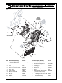
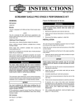
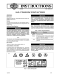
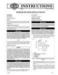
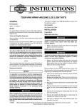
INSTRUCTIONS
®
REV. 07-03-2003
-J03021
Kit Number 26721-01A
VRSC RADIATOR KIT
General
Installing the New Radiator Assembly
This kit fits all 2002 and later VRSC (V-Rod®) models.
1. Hold the new radiator/ oil cooler assembly up to the
motorcycle frame.
See the Service Parts illustration for kit contents.
NOTE
This instruction sheet references Service Manual information. A Service Manual for your model motorcycle is required
for this installation and is available from any HarleyDavidson Dealer.
Removing the Existing Radiator Assembly
1WARNING
Do not remove radiator filler cap when engine is hot. The
cooling system is under pressure and hot coolant and
steam can escape, which could cause severe burns.
Allow engine to cool before servicing the cooling system.
(00091a)
1WARNING
To prevent accidental vehicle start-up, which could
cause death or serious injury, disconnect negative (-)
battery cable before proceeding. (00048a)
2. Line up and fit the radiator inlet and outlet pipes to the
engine coolant hoses.
3. See Figure 1. Supporting the radiator/ oil cooler assembly, push the oil line into the “oil out” fitting on the engine
oil filter until it clicks in place under the spring clip.
NOTE
The yellow witness band on the flanged oil line will not be visible if the oil line has been correctly snapped into the fitting.
4. Snap the plastic dust cap over the spring clip groove.
NOTE
The dust cap will not snap onto the fitting if the oil line is not
correctly installed on the fitting.
5. Thread on, but do not tighten, the nuts holding the radiator/ oil cooler assembly to the engine mount studs.
6. Push the remaining oil line into the “oil in” fitting on the
crankcase until it clicks in place under the spring clip.
Snap the plastic dust cap over the spring clip groove.
1. Refer to BATTERY MAINTENANCE, DISCONNECTION in the Service Manual to disconnect the maxi-fuse
and negative battery cable.
2. Cover the front fender with a shop towel or protective
cover.
i02401.tif
3. Refer to RADIATOR/ OIL COOLER, REMOVAL in the
Service Manual to remove the radiator assembly. It will
not be necessary to remove the air filter or velocity
stacks.
2004 and Later Models
4. Proceed to “Installing the New Radiator Assembly”. The
two quick-connect oil fittings (23) and cable strap (28) in
the kit can be discarded.
2002-2003 Models
4. Refer to OIL LINE FITTINGS, REMOVAL in the Service
Manual to remove the “oil in” fitting at the crankcase
and the “oil out” fitting at the oil filter.
5. Obtain the two quick-connect oil fittings (23) from the kit.
Thread the fitings into the holes in place of the original
fittings Tighten the fittings to 40-44 Nm (29-32 ft-lbs).
Figure 1. Flanged Oil Line
1 of 3
7. Install the grommets (18) into the holes in the radiator/
oil cooler crossmember. Assemble the crossmember to
the mounting pins on the bottom of the oil cooler. Install
the crossmember to the frame.
8. Lightly tug on the oil lines to verify that they are securely
locked to the fittings.
9. Tighten the cooling system fasteners as follows:
• Cross member fasteners to 20-26 Nm (15-19 ft-lbs).
• Top mounting nuts (22) to 19-27 Nm (15-20 ft-lbs).
17. Install the air cleaner cover and the decorative air box
cover. See AIRBOX AND AIR FILTER in the Service
Manual.
CAUTION
Do not over-tighten bolts on battery terminals. Use recommended torque values. Over-tightening battery terminal bolts could result in damage to battery terminals.
(00216a)
• Pipe clamp to 6.5 Nm (57 in-lbs).
18. Reinstall the negative battery cable. Tighten to 6.8-10.8
Nm (60-96 in-lbs).
• “P”-clamp to 6-10 Nm (53-88 in-lbs).
19. Install the maxi-fuse and right side cover.
• Hose clamps to 3-4 Nm (27-35 in-lbs).
CAUTION
10. Route the drain hose (7) to the overflow bottle.
11. Secure the voltage regulator connector to the top plate
of the radiator
• 2002-2003 Models: Use the cable strap (28) from
the kit.
• 2004 and Later Models: Use the cable strap
already assembled to the connector.
The “rosebud” on the strap snaps into the hole in the
radiator top plate.
12. Install the radiator cover.
13. Make the electrical connections as follows:
• Mate the crank position sensor connector [79]
halves.
• Mate the top [97T] and bottom [97B] cooling fan
connector halves.
• Mate the stator to voltage regulator connector [46]
halves.
• Push the top fan connector [97T] into the radiator
cover.
Use a cable strap (not provided) to tie the fan wiring
harness to the crank position sensor wiring harness
14. Install the left- and right-side radiator trim covers.
15. Fill the engine with oil. See ENGINE OIL AND FILTER
in the Service Manual.
When closing the seat, make sure the ignition switch is
in the FUEL position. If the ignition switch is in any
other position when the seat is closed, the seat latch
mechanism could be damaged. (00196a)
20. Close the seat, then start the engine. While the engine
is running, inspect the oil fittings for leaks. If leaks are
found, turn off the engine and correct.
Check the coolant level in the overflow bottle with the
coolant cold and the motorcycle on the jiffy stand. If the
coolant level is below the COLD FULL line, remove the
cap from the overflow bottle and add Genuine HarleyDavidson Extended Life Antifreeze & Coolant until the
fluid level reaches the COLD FULL line.
Continue to run the engine, checking for oil leaks.
Watch the coolant level and add fluid until the level
remains at the COLD FULL line with the motorcycle on
the jiffy stand.
Turn off the engine, check the oil level and add oil if
required.
Radiator Maintenance
CAUTION
Carefully clean the front surface of the radiator regularly.
Leaves and other debris can collect on the radiator surface and degrade radiator performance. This could lead
to engine overheating and engine damage. (00197a)
16. Remove the radiator pressure cap. Loosen the air bleed
plug. Fill the radiator with Genuine Harley-Davidson
Extended Life Antifreeze & Coolant through the filler
neck. See ENGINE COOLANT in the Service Manual.
Tighten the air bleed plug to 9-11 Nm (80-97 in-lbs).
and reinstall the pressure cap.
-J03021
2 of 3
®
Part No. 26721-01A
Service Parts
Date 07/03
VRSC Radiator Kit
i02400
Voltage
regulator
connector
20
28
19
15
5
18
Crossmember
2
16,
17
18
21
6
22
4
10
3
13
23
27
25 26
10
10
24
7
12
8
11
14
Item Description (Quantity)
1
Cooling module
(consists of items 2-22)
2
Radiator
3
Plug
4
Hose ass’y, oil cooler inlet
5
Hose ass’y, oil cooler outlet
6
Cap
7
Hose, drain
8
Cable strap (3)
9
Oil cooler assembly
10
Screw (8)
11
Nut (4)
12
Screw (2)
13
Bracket
14
“O”-ring (2)
-J03021
Part No.
Not sold separately
26722-04
5235
62940-04
62941-04
62909-04
62953-01
10065
26723-04
5237M
5238M
5236M
26772-04
11101
9
Item
15
16
17
18
19
20
21
22
23
24
25
26
27
28
Description (Quantity)
Part No.
Fan assembly
26724-04
Socket housing, 2-place (2)
73152-96BK
Contact, socket (4)
73191-96
Grommet (4)
26757-01
Bushing (2)
11568
Spacer (2)
26758-01
Washer, front (2)
6838M
Nut (2)
3725M
Oil feed/ return fitting ass’y (2) 63650-04K
(consists of items 24-27)
Fitting, oil feed/ return
Not sold separately
“O”-ring, 13.3mm (.52 in) I.D. 10994K
“O”-ring, 12.4mm (.49 in) I.D. 11140
Retainer, wire clip
11384K
Cable strap, rosebud mount
10073
3 of 3