1
~9 J ICS 14
SERVICE
MANUAL
FOR
BF POWER DRAWER
4KW ELECTRIC POWER PLANT
FOR
RECREATIONAL VEHICLES
© 2006 UsefulCDs
http://stores.ebay.com/UsefulCDs
TABLE OF CONTENTS
General Information
2
Specifications
4
Dimensions and Clearances 5
Assembly Torques
6
Special Tools
6
Engine Troubleshooting Guide 7
Engine Disassembly
8
Oil System
19
Fuel System
20
Fuel System Troubleshooting Guide24
Ignition and Battery Charging 26
Testing Battery Charging System 28
Starting System
29
AC Generator Maintenance 36
Generator Troubleshooting Guide 42
Controls
44
Control System Troubleshooting Guide 46
Remote Accessories
49
Plant Wiring Diagram
52
© 2006 UsefulCDs
1
http://stores.ebay.com/UsefulCDs
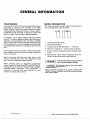
GENERAL INFORMATION
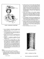
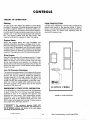
YOUR MANUAL
MODEL DESIGNATION
This manual contains information required for proper
maintenance, servicing and overhaul of the 4KW
Power Drawer . Study the entire manual to better
understand how the plant functions . This will help in
maintenance and servicing of the plant, which will
result in longer life and more reliable operation .
The following typical model number is broken down
into code segments used by Onan .
4 .0 BF - 1 R9500A
1
T1TTT
If possible, use a parts catalog with the service
manual . The parts catalog will give a good picture of
assembly and disassembly and will help to identify
plant components . Since the first and most important
part of repair work is correct diagnosis of the trouble,
troubleshooting charts are included to help find the
fault .
1 2
5 6
1 . Indicates kilowatt rating .
2 . Series identification .
3 . Voltage code of the generator, 1 = 120 volts .
4 . Method of starting : R - remote electric starting .
A list of special tools is included in the manual . These
are available from Onan, and will make it easier to
work on the plant .
5 . Factory codefordesignating optional equipment,
if any .
6 . Specification letter which advances when the
factory makes production modifications .
When discussing left side and right side in this
manual, view the plant from the engine end of the
plant, which is designated the front end .
Onan uses this symbol throughout the text to
warn of possible equipment damage .
When ordering parts or requesting information
always supply the complete MODEL and SPECIFICATION as shown on the Onan nameplate (see "MODEL
DESIGNATION" following) . This information is
necessary to identify your plant among the many
models manufactured by Onan .
© 2006 UsefulCDs
3 4
` WA R NING
` This symbol is used to warn of any possible
personal Injury .
Service information contained herein applies to Model 4 .OBF1R/9500 . The basic information can also be used when servicing
Model 4 .OBF-1 R/9000 .
2
http://stores.ebay.com/UsefulCDs
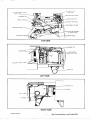
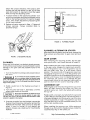
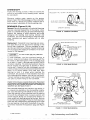
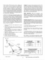
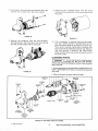
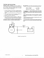
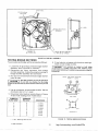
35 AMP CIRCUIT
BREAKER
BREAKER POINT BOX
INTAKE MANIFOLD
CHOKE LINKAGE
EXHAUST MANIFOLD
GOVERNOR LINKAGE
DIPSTICK AND OIL FILL
DOT BUTTON (ACCESS
TO TIMING MARK
ELECTRIC CHOKE
BLOWER SCROLL
TOP VIEW
LEFT SIDE
RIGHT SIDE
© 2006 UsefulCDs
3
http://stores.ebay.com/UsefulCDs
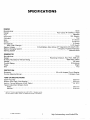
SPECIFICATIONS
ENGINE
Onan
Manufacturer
Four
Cycle,
Air
Cooled,
L
Head
Design
Gasoline
Fuel
12V, Electric
Fuel Pump
Two
Cylinders
3-1/8
Inch
Bore
2-5/8
Inch
Stroke
3
Quarts
Oil Capacity
3-1/2 Quarts
(With Filter Change) 12
Volt
Battery
Size
(Above
0°
F
Operation)
45
Amp/hr Min .
Battery Voltage
9 Ampere, Flywheel Alternator
Battery Charging System
Solenoid Shift
Starting System
GENERATOR
Manufacturer Design
60 Hertz Recreational Vehicle Rating
Voltage
Current Rating
Phase
Wire
Onan
Revolving Armature, Four Pole, 1800 rpm
4000 Watts (4KW)
120 Volts
33 Amperes
Single
Two
PROTECTION
Generator Control (Remote Wiring) 35 or 40 Ampere Circuit Breaker
5 Ampere Fuse
TUNE-UP SPECIFICATIONS
Spark Plug Gap
Breaker Point Gap (Cold Setting)
Ignition Timing Reference (Cold, Static)
Tappet Adjustment (Engine Cold)
Intake
Exhaust
.020 Inch
.025 Inch
** 26° BTC
.003 Inch
.010 Inch
Ignition Timing is permanently set at 26° BTC . If breaker points
are set properly ( .025" Cold), no additional timing is necessary .
© 2006 UsefulCDs
4
http://stores.ebay.com/UsefulCDs
DIMENSIONS AND CLEARANCES
All dimensions and clearances given in inches unless otherwise specified .
Readings taken at 70° F .
Minimum
CYLINDER AND PISTON
Piston to Pin (70°)
.001
Pin to Connecting Rod Clearances .0002
Piston Ring Gap in Cylinder .010
Piston Clearance in Cylinder, Solid Type Measured .10 Below Oil Controlling Ring - 90° From Pin .003
Cylinder Bore - Honed Std 3 .1265
CRANKSHAFT AND CAMSHAFT
Crankshaft Main Bearing Journal to
Bearing Clearance . Steel Backed Aluminum
Crankshaft End Play
Camshaft End Play
Crankshaft Rod Journal to Rod Bearing
Clearance . Aluminum Rod
Connecting Rod End Play Timing Gear Backlash
Oil Pump Gear Backlash
TAPPET AND VALVES
Tappet to Cylinder Block Clearance Valve Seat Width
Valve Stem to Guide - Intake
Valve Stem to Guide - Exhaust
Valve Face Angle
Valve Seat Angle
Valve Tappet Clearance - Intake 70° F
Valve Tappet Clearance - Exhaust 70" F
Maximum
.005
.0007
.020
.005
3 .1275
.0025
.006
.003
.0038
.012
.0020
.002
.002
.002
.0033
.016
.003
.0015
1/32
.0010
.0025
.0030
1/8
.0025
44
45
003"
.010"
7
© 2006 UsefulCDs
r)
http://stores.ebay.com/UsefulCDs
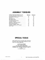
ASSEMBLY TORQUES
TORQUE SPECIFICATIONS IN LB . FT .
Connecting Rod Bolt - Aluminum Rod
Flywheel Mounting Screw
Oil Pump
Gearcase Cover
Rear Bearing Plate
Oil Base Mounting Screws
Cylinder Head Nuts
Manifolds - Intake and Exhaust
Starter Mounting Bolts Generator Through - Studs
Armature Holddown Nut (12-point) Spark Plugs
Minimum
14
35
7
8
25
18
14
8
18
15
45
15
Maximum
16
40
9
10
27
23
16
10
20
18
50
20
SPECIAL TOOLS
These special tools are required when overhauling
the engine . Other tools are also available from Onan .
Order Tool Catalog (900-0019) .
VALVE SEAT DRIVER
VALVE GUIDE DRIVER
OIL SEAL GUIDE AND DRIVER
COMBINATION BEARING DRIVER (MAIN & CAM)
COMBINATION BEARING REMOVER (MAIN &
CAM)
FLYWHEEL PULLER
© 2006 UsefulCDs
6
http://stores.ebay.com/UsefulCDs
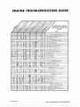
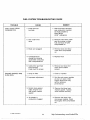
ENGINE TROUBLESHOOTING GUIDE
y
yaa 4S' caa4a`
+ a
o`
a`c ao~~~aa c
4
GASOLINE ENGINE
TROUBLESHOOTING
GUIDE
a~
~xo
a
O
oc
CAUSE
Qy
STARTING SYSTEM
Loose or Corroded Battery Connection
IGNITION SYSTEM
Ignition Timing W ong
Wrong Spark Plug Gap
Wo n Poin s o Imp oper Gap Sett ng
Bad Ignit on Co I or Condense
Faulty Spa k Plug Wires
FUEL SYSTEM
Out of Fuel Check
Lean Fuel Mixture
Readjust
Rich Fuel Mixtu e or Choke Stuck
Engine Flooded
Poor Qual ty Fuel
Dirty Carburetor
Dirty A Cleaner
Dirty Fuel Filter
Defec ive Fuel Pump
INTERNAL ENGINE
W ron R Valve Clearance
Broken Valve S in
Valve or Valve Seal Leaking
Piston Rings Worn or Broken
Wrong Bearin g Clearance
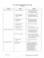
COOLING SYSTEM (AIR COOLED)
Poo Air C culation _
0
y or 0 y Cooling Firs
Blov n Head Gas et
LUBRICATION SYSTEM
Defective Oil Gauge
Retie Valve Stuck
Faulty 0 I Pump
•
•
Dirty Oil or Filter
Oil Too Light or Dilu ed
Oil Le el Low
Oil Too Heavy
Dirty Crankcase Breather Val e
THROTTLE AND GOVERNOR
Lin age Out of Adjustment
Lin age Worn or Disconnec ed
Governor Spring Sensitivity Too Great
Linkage Binding
© 2006 UsefulCDs
7
http://stores.ebay.com/UsefulCDs
ENGINE DISASSEMBLY
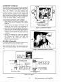
GENERAL
ASSEMBLY
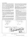
A 3/8-16 threaded hole in manifold provides space for
a lifting eye for removing power plant from vehicle .
When complete engine disassembly is necessary,
first remove all complete assemblies . Individual
assemblies like fuel pump and carburetor can be
disassembled and repaired at another time .
The engine assembly procedure is normally the
reverse of the disassembly procedure, observing
proper clearances throughout the engine . Use a
torque wrench to assure proper tightness . Coat the
internal engine parts with SAE 30 oil as they are
assembled . After the internal engine parts are
assembled, the engine should turn over by hand
freely . Use only genuine Onan parts and Onan special
tools when reassembling your engine .
DISASSEMBLY
Common sense dictates the order of disassembly and assembly .
The suggested disassembly procedure is as follows :
1 . Use the proper bearing driver to install front main
bearing after coating it with a light film of oil .
2 . Insert rear main bearing in rear bearing plate .
1 . Drain crankcase oil .
2 . Disconnect all exhaust lines, fuel lines and electrical wires (tag all electrical wires) .
3 . Install crankshaft and rear bearing plate .
3 . Remove engine from its slide rails and mountings
and place on a suitable bench or work stand .
4 . Install connecting rods, pistons and bearings .
5 . Install camshaft and gear .
4 . Remove all shrouds, mounts, air cleaner, control
box, etc .
6 . Install valve assemblies .
7 . Install oil pump, oil base and cylinder heads .
When removing generator and control box, tag all wires according
to their respective locations .
8 . Install breaker box .
9 . Install fuel pump, oil filter, starter, generator,
carburetor, fuel lines, spark plugs, etc .
10 . Install crank gear, aligning crank gear mark with
camshaft .
5 . Remove flywheel, using a puller or pry-bar
method .
6 . Remove flywheel alternator stator .
7 . Remove the gear cover, being careful to protect
the oil seal from keyway damage .
8 . Remove the crank gear, using a gear puller and
ring .
11 . Install gear cover and oil seal .
12 . Install flywheel alternator stator .
13 . Install flywheel .
14 . Install all housings, air cleaner, control box, etc .
9 . Remove fuel pump, oil filter, starter, carburetor,
fuel lines, spark plugs, etc .
10 . Remove breaker box .
15 . Reinstall power plant in vehicle, making proper
fuel, battery, electrical and exhaust connections .
(Refer to wiring diagram when making electrical
connections) .
11 . Remove oil base, oil pump and cylinder heads .
12 . Remove valves, springs, lifters, etc .
13 . Remove camshaft and gear assembly .
14 . Remove connecting rods, pistons and bearings .
15 . Remove rear bearing plate .
16 . Fill crankcase with oil .
OPERATIONAL CHECKOUT
1 . Start engine .
2 . Check oil pressure .
16 . Remove crankshaft .
17 . Remove front main bearing .
3 . Run engine approximately 15 minutes to bring up
to operating temperature .
4 . Check for oil leaks, security of electrical connections, fuel lines and exhaust connections .
Keep all parts in their respective orders . Keep valve
assemblies together . Return rod caps to their respective pistons . Analyze the reasons for parts failure . See
specific sections of this manual covering dimensions
of parts, tolerance and wear limits, etc .
© 2006 UsefulCDs
5 . Adjust carburetor and governor linkage .
6 . Check output voltage and frequency both at a noload and full load condition .
8
http://stores.ebay.com/UsefulCDs
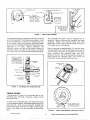
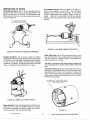
VALVE SYSTEM
Properly seated valves are essential to good engine
performance . The aluminum cylinder heads are
removable for valve servicing . Do not use a pry to
loosen the cylinder head ; rap sharply on the edge with
a soft faced hammer, taking care not to break any
cooling fins . A conventional type valve spring lifter
may be used when removing the split type valve
spring locks . Clean all carbon deposits from the
cylinder heads, piston tops, valves, guides, etc . If a
valve face is burned or warped, or the stem worn,
install a new valve . Refer to Figure 1 .
Remove all grinding compound from engine parts
and place each valve in its proper location . Make
pencil marks at intervals across the valve face and
observe if the marks rub off uniformly when the valve
is rotated part of a turn against the seat .
Valve locks are split, tapered type, the smaller
diameter of which must face toward the valve head .
Tappets are also replaceable from the valve chamber,
after first removing the valve assemblies .
1 . Remove all parts necessary to gain access to
valve tappets .
The valve / we angle is 44 degrees . The valve seatangle
is 45 degrees . This 1 degree interference angle results
in a sharp seating surface between the valve and the
top of the valve seat . The interference angle method
of grinding valves minimizes face deposits and
lengthens valve life .
3 . Use the engine flywheel to turn the engine over
slowly by hand until the left hand intake valve
opens and closes . Continue turning the flywheel
until the TC mark is on the top and lined up with
the TC mark on the gear cover . Both valves should
be closed . This should place the left hand piston
at the top of its compression stroke, the position it
must be in to get proper valve adjustment for the
left cylinder .
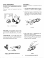
Tappet Adjustment : The engine is equipped with
adjustable valve tappets . The valve tappet clearance
should be checked and adjusted when necessary .
Adjust the valve clearance only when engine is at
ambient temperature . Proceed as follows :
2 . Remove spark plugs to ease the task of turning
the engine over by hand .
The valves should not be hand lapped,
because the sharp contact may be destroyed .
This is especially important where stellite faced valves and seats
are used .
4 . For the intake valve, a .003 inch thickness gauge
should just pass between valve stem and tappet .
5 . For the exhaust valve, a .01 0 inch thickness gauge
should just pass between valve stem and tappet .
6 . To correct the valve clearance, use a 7/16 inch
open end wrench to turn the adjusting screw to
Valve faces should be finished to 44 degrees . Valve
seats should be ground with a 45 degree stone and the
width of the seat band should be 1 /32 inch to 3/64 inch
wide . Grind only enough to assure proper seating .
VALVE- .1
VALVE
t>
/v
i
4 yC<
A?73
SEAT
SEAT
FR~tiC~
WRONG
RIGHT
NOTE : USE A STANDARD AUTOMOTIVETYPE WRENCH TO ADJUST THE
TAPPETS .
VALVE SEAT
Er
VALVE RETAINER
VALVE SPRING
VALVE GUIDE '-'
FIGURE 1 . VALVE SYSTEM
© 2006 UsefulCDs
9
http://stores.ebay.com/UsefulCDs
obtain the correct clearance . The screw is selflocking and will stay where it is set . A 9/16 inch
open end wrench is required to hold the tappet
while turning the adjusting screw .
7 . To adjust valves on the right hand cylinder-turn
engine one complete revolution and again line up
mark on the flywheel and the TC mark on the gear
cover . Then follow adjustment procedure given
for left hand cylinder .
8 . Replace all parts removed in Step 1 . Tighten all
screws securely . Torque manifold bolts to
specified torque .
11
-
k_/
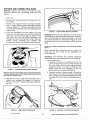
FIGURE 3 .
FLYWHEEL PULLER
FLYWHEEL ALTERNATOR STATOR
After disconnecting stator terminal wires, remove the
three screws securing stator to gear cover and pull
off .
FIGURE
2. ADJUSTING VALVES
GEAR COVER
After removing the mounting screws, tap the gear
cover gently with a soft faced hammer to loosen it .
FLYWHEEL
Removing the flywheel is a relatively simple process,
but the following procedure must be followed to avoid
damage to the gear case and possible injury to the
operator .
When installing the gear cover, make sure that the pin
in the gear cover engages the metal lined (smooth)
hole in the governor cup . Turn the governor cup so
that the metal lined hole is at the three o'clock
position . The smooth side of the governor yoke must
ride against the governor cup . Turn the governor arm
and shaft clockwise as far as possible and hold in this
position until the gear cover is installed flush against
the crankcase . Be careful not to damage the gear
cover oil seal . Adjust the roll (stop) pin to protrude to a
point 3/4 inch from the cover's mounting surface .
1 . Turn the flywheel mounting screw outward about
two turns .
WARNING
F
Do not remove the screw completely since it
acts as a restrainer when the flywheel snaps
loose. If the flywheel is not held by the screw, the spring action in
the wheel will cause it to fly off with great force which can cause
injury to the operator.
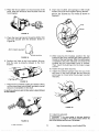
GOVERNOR CUP
2 . Install a puller bar on the flywheel as shown in
Figure 3 .
With the gear cover removed, the governor cup can be
taken off after removing the snap ring from the
camshaft center pin . Catch the flyballs while sliding
the cup off .
3 . Turn the puller bar bolts in, alternately, until the
wheel snaps loose on the shaft .
Do not use a screwdriver or similar tool or pry
behind the flywheel against the gear case .
The gear case cover is die-cast material and will break if undue
pressure is applied in this manner.
4 . Unscrew the puller from the flywheel, remove
flywheel mounting screw and washer and pull
flywheel off the shaft . Take care not to drop
wheel . A bent or broken fin will destroy
balance . Always use a steel key for mounting
flywheel .
© 2006 UsefulCDs
Replace with a new part, any flyball which is grooved
or has a flat spot ; the ball spacer if its arms are worn or
otherwise damaged ; and the governor cup if the race
surface is grooved or rough . The governor cup must
be a free spinning fit on the camshaft center pin, but
without any excessive play .
the
the
the
the
the
When installing the governor cup, tilt the engine so
the gear is up, then put the flyballs in place . Install the
cup and snap ring on the center pin .
10
http://stores.ebay.com/UsefulCDs
GOVERNOR CUP
ROTATE
GOVERNOR CUP
SO THAT ROLL PIN
FITS INTO THE
METAL LINED
HOLE IN THE CUP
A359a .
IF FEELER WILL
ENTER HOLE I/2"
BALL HAS
FALLEN OUT
FIGURE 4 .
GEAR COVER ASSEMBLY
The camshaft center pin extends out 3/4 inch from the
end of the camshaft . This distance provides an in and
out travel distance of 7/32 inch for the governor cup,
as illustrated . Hold the cup against the flyballs when
measuring . If the distance is less (the engine will race,
especially at no load), replace camshaft . The
camshaft center pin cannot be pulled outward or
removed without damage . If the center pin extends
out too far, the cup will not hold the flyballs properly .
The camshaft and gear must be replaced as an
assembly . Before removing the camshaft and gear
assembly, remove the cylinder head and valve
assemblies . Then remove the operating plunger for
the breaker points and tappets .
Each timing gear is stamped with "0" near the edge .
The gear teeth must mesh so that these marks exactly
coincide when the gears are installed in the engine .
When installing the camshaft gear and shaft
assembly, be sure that the thrust washer is properly in
place behind the camshaft gear . Then install the
crankshaft retaining washer and lock ring .
WHEN GOVERNOR
IS PROPERLY
ASSEMBLED THE
DIMENSION SHOWN
ON DRAWING WILL
BE AS INDICATED
CAMSHAFT
FIGURE 5 .
GOVERNOR CUP CROSS-SECTION
TIMING GEARS
If replacement of either the crankshaft gear or the
camshaft gear becomes necessary, always install
both gears new .
To remove the crankshaft gear, first remove the snap
ring and retainer washer, then attach gear pulling ring
using two No . 10-32 screws (Figure 6) . Tighten the
screws alternately until both are tight . Attach a gear
puller to the puller ring and proceed to remove the
gear .
© 2006 UsefulCDs
~_
A20
FIGURE 6 .
11
a
"
`J Y
a~
THESE MARKS MUST
ALIGN WHEN INSTALLING
ING TIMING GEARS .
TIMING GEAR REMOVAL AND INSTALLATION
http://stores.ebay.com/UsefulCDs
PISTONS AND CONNECTING RODS
Removal: Observe the following procedure when
removing pistons and connecting rods from the
engine .
1 . Drain oil .
2 . Remove the cylinder heads and oil base pan from
the engine .
3 . Remove the ridge from the top of each cylinder
with a ridge reamer before attempting piston
removal (Figure 7) . Forcing the piston from the
cylinder before reaming may cause damage to the
piston lands .
FIGURE 9 . PISTON RING GROOVE CLEANING
4 . Turn the crankshaft until the piston is at the
bottom of its stroke and remove the connecting
rod bolts . Lift the rod bearing cap from the rod
and push the rod and piston assembly out
through the top of the cylinder using a hammer
handle . Avoid scratching the crankpin and
cylinder wall when removing the piston and rod .
Cleaning : Remove dirt and deposits from the piston
surfaces with an approved cleaning solvent . Clean the
piston ring grooves with a groove cleaner or the end
of a piston ring filed to a sharp point (Figure 9) . Care
must be taken not to remove metal from the groove
sides .
Do not use a caustic cleaning solvent or wire brush for cleaning
pistons .
When cleaning the connecting rods in solvent, include the rod bore . Blow out all passages with
compressed air.
FIGURE 7 .
Inspection : The following text contains inspection
procedures concerning pistons and connecting rods .
1 . Piston Inspection :
a . Inspect the pistons for fractures at the ring
lands, skirts and pin bosses . Check for wear at
the ring lands using a new ring and feeler
gauge as shown in Figure 10 . Replace the
piston when the side clearance of the top
compression ring reaches 0 .008 inch .
b . Replace pistons showing signs of scuffing,
scoring, worn ring lands, fractures or damage
from preignition . Excessive piston wear near
the edge of the top ring land indicates preignition .
REMOVING RIDGE FROM CYLINDER
Mark each piston and rod assembly so they can be returned to their
respective cylinders after overhaul . Keep connecting rod bearing
caps with their respective rods .
5 . Remove the piston rings from the piston with a
piston ring spreader as shown in Figure 8 .
Remove the piston retainer and push the piston
pin out .
FIGURE 8 .
REMOVING PISTON RINGS
© 2006 UsefulCDs
FIGURE 10 . CHECKING RING SIDE CLEARANCE
12
http://stores.ebay.com/UsefulCDs
ti 00000 ,'
04--MEASURE CLEARANCE HERE _~~
FIGURE 11 . MEASURING PISTON CLEARANCE
2 . Connecting Rod Inspection :
a . Replace connecting rod bolts or nuts with
damaged threads . Replace connecting rods
with deep nicks, signs of fractures, scored
bores or bores out of round more than 0 .002
inch .
b . Use a new piston pin to check connecting rod
for wear . A push fit clearance is required and
varies from engine to engine . If a new piston
pin falls through a dry rod pin bore as a result
of its own weight, replace the rod .
FIGURE 12 . CHECKING PISTON RING END GAP
CYLINDER BLOCK
Inspection :
1 . Make a thorough check for cracks . Small cracks
may be detected by coating the suspected area
with a mixture of 25 percent kerosene and 75
percent light motor oil . Wipe the part dry and
immediately apply a coating of zinc oxide (white
lead) dissolved in wood alcohol . If cracks are
present, the white coating will become discolored
at the defective area .
REPAIR
1 . Fitting Pistons :
a . Proper piston tolerances must be maintained
for satisfactory operation .
b . Measure the piston as shown in Figure 11 to be
sure the total piston-to-cylinder clearance
follows specifications .
2 . Inspect the cylinder bore for scoring and cooling
fins for breakage .
2 . Fitting Piston Rings :
a . Install the piston ring in the cylinder bore .
Invert the piston and push the ring to the end of
ring travel, about halfway into the bore, which
trues the ring end gap . Check the gap with a
feeler gauge as shown in Figure 12 .
3 . Check the cylinder bore for taper, out of round
and wear, with a cylinder bore gauge, telescope
gauge or inside micrometer (Figure 13) . These
measurements should be taken at four places the top and bottom of piston ring travel .
4 . Record measurements taken lengthwise at the
top and bottom of the piston travel as follows :
b . The practice of filing ring ends to increase the
end gap is not recommended . If the ring end
gap does not meet specifications, check for the
correct set of rings and correct bore size . A
cylinder bore that is 0 .001 inch under size will
reduce the end gap 0 .003 inch .
© 2006 UsefulCDs
a . Lengthwise of the block, measure and record
as "A" the diameter of the cylinder at the top of
the cylinder where greatest ring wear occurs .
13
http://stores.ebay.com/UsefulCDs
3 . Connect drill to hone and start drill . Move the
hone up and down in the cylinder approximately
40 cycles per minute . Usually the bottom of the
cylinder must be worked out first because it is
smaller . Then when the cylinder takes a uniform
diameter, move the hone up and down all the way
through the bore . Follow the hone manufacturer's
recommendations for wet or dry honing and
oiling the hone .
4 . Check the diameter of the cylinder regularly
during honing . A dial bore gauge is the easiest
method but a telescoping gauge can be used .
Check the size at six places in the bore : measure
twice at the top, middle and bottom at 90 degree
angles .
5 . The crosshatch formed by the scratching of the
stones should form an angle of 23 degrees . This
can be achieved by moving the hone up and down
in the cylinder about 40 cycles per minute .
6 . Clean the cylinder block thoroughly with soap,
water and clean rags . A clean white rag should not
be soiled on the cylinder wall after cleaning is
complete . Do not use a solvent or gasoline since
they wash the oil from the walls but leave the
metal particles .
7 . Dry the crankcase and coat it with oil .
FIGURE 13. MEASURING CYLINDER BORE
b . Also, lengthwise of the block, measure and
record as "B" the cylinder diameter at the
piston skirt travel .
c . Crosswise of the block, measure and record as
"C" the diameter of the top of the cylinder at
the greatest point of wear .
d . Measure and record as "D" the diameter at the
bottom of the cylinder bore and crosswise of
the block .
e . Reading "A" compared to reading "B" and
reading "C" compared to reading "D" indicates
cylinder taper .
f . If cylinder taper exceeds 0 .005 inch, rebore
and hone to accommodate the next oversize
piston . Reading "A" compared to reading "C"
and reading "B" compared to reading "D"
indicates whether or not the cylinder is out of
round . If the out of round exceeds 0 .002 inch,
the cylinders must be rebored and honed for
the next oversize piston . A reboring machine is
used when going to oversize pistons . The
following repair data covers honing to oversize
by use of a hone .
PRODUCE CROSS HATCH SCRATCHES
FOR FAST RING SEATING
Repair:
1 . A hone can be used to refinish a cylinder .
2 . Anchor the block solidly for either vertical or
horizontal honing . Use either a drill press or
heavy-duty drill which operates at approximately
250 to 450 rpm .
© 2006 UsefulCDs
FIGURE 14. CROSSHATCH PATTERN
14
http://stores.ebay.com/UsefulCDs
CRANKSHAFT
Inspect the bearing journals . If they are scored and
cannot be smoothed out by dressing down, replace
the crankshaft .
PRECISION TYPE - DO NOT LINE REAM OR BORE .
Whenever making major repairs on the engine,
always inspect the drilled passages of the crankshaft .
Clean them to remove any foreign material and to
assure proper lubrication of the connecting rods .
ALIGN HOLE IN BEARING
7/32''
FROM
OUTSIDE
BEARINGS (Figures 15-18)
CAMSHAFT BEARING
Removal : Removing camshaft or crankshaft bearings
requires complete disassembly of the engine . Use a
press or a suitable drive plug to remove the bearings .
Support the casting to avoid distortion and avoid
damaging the bearing bore during removal and
installation . Use oil on the bearings to reduce friction
when installing and again lubricate with oil after
installing .
FIGURE 15 . CAMSHAFT BEARINGS
Replacement : Crankshaft main bearings are precision type which do not require line reaming or line
boring after installation . They are available in standard size and .002 inch undersize . Expand the bearing
bore by placing the casting in hot water or in an oven
heated to 200 degrees F .
LOCK PIN
ALIGN BEARING OIL HOLES
WITH OIL HOLES IN
BEARING BORE
If a torch is used, apply only a little heat .
To ease assembly, cool the precision bearing to
shrink it . Align the oil hole(s) in the bearing with the
oil hole(s) in the bearing bore . The oil passage must
be at least 1/2 open . Lubricate bearings with SAE20
oil before installing . The cold oiled precision bearing
should require only light taps to position it with a
driving tool . If head of lock pin is damaged, use side
cutters or Easy Out tool to remove and install new pin .
Apply oil to thrust washer (one used with each
bearing) to hold it in place while installing the
crankshaft . Oil grooves in thrust washers must face
the crankshaft and washers must be flat (not bent) .
The two notches on each washer must fit over the two
lock pins to prevent riding on the crankshaft .
FIGURE 16 . REAR MAIN BEARING
FRONT MAIN
BEARING BORE
Original front bearing uses a separate thrust washer . Replacement
front bearing is a one piece assembly with thrust washer part of the
bearing . Do not use a separate thrust washer when installing this
replacement part . See Figures 16 and 17 .
New camshaft bearings are precision type which do
not require line reaming or line boring after installation . Coat the bearing with SAE20 to reduce friction .
Place the bearing on the crankcase over the bearing
bore with the elongated hole in proper position and
narrow section facing out (except bores without oil
holes install with bearing groove at the top) . Be sure
to start the bearing straight . Press the front bearing in
flush with the outside end of the bearing bore . Press
the rear bearing in flush with the bottom of counterbore which received the expansion plug (see Figure
15) .
ALIGN BEARING
NOTCHES WITH
LOCK PINS
AND MATCH
OIL HOLES
B49 Rev
PRECISION TYPE DO NOT LINE BORE OR REAM
FIGURE 17 . FRONT MAIN BEARING
© 2006 UsefulCDs
15
http://stores.ebay.com/UsefulCDs
CRANKSHAFT ENDPLAY
After the rear bearing end plate has been tightened
using the torque recommended in ASSEMBLY TORQ('ES check the crankshaft endplay as shown in
Figure 18 . If there is too much endplay (see
DI .LIENSIONSAND CLEA RANCESfor minimum and
maximum endplay), remove the rear bearing end
plate and add a shim between the thrust washer and
plate . Reinstall the end plate making sure the thrust
washer and shim notches line up with the lock pins .
Torque and recheck endplay of the crankshaft .
Checking Bearing Clearance with Plastigage :
1 . Make certain that all parts are marked or identified so that they are installed in their original
positions .
2 . Place a piece of correct size Plastigage in the
bearing cap the full width of the crankshaft rod
surface about 1/4 inch off center (Figure 19) .
3 . Rotate the crank about 30 degrees from bottom
dead center and reinstall the bearing cap ; tighten
the bolts to the torque specified in the TABLE OF
TORQUES AND CLEARANCES . Do not turn the
crankshaft .
FIGURE 18 . CRANKSHAFT ENDPLAY
4 . Remove the bearing cap . Leave the flattened
Plastigage on the part to which it has adhered
and compare the widest point with the
graduations on the
Plastigage envelope to
determine bearing clearance .
OIL SEALS (Figure 20)
The bearing plate must be removed to replace the oil
seal . Drive the oil seal out from the inside .
Before installing the seals, fill the space between lips
with a multi-purpose grease . This will improve sealing .
FIGURE 19. MEASURING BEARING CLEARANCE
GEAR COVER
01-1 -
- MOUNTING FACE
OF GEAR COVER
OIL SEAL
*31/32"
A877
THIS SURFACE SHOULD BE
CLEANED OF ALL OLD
SEALING COMPOUND BEFORE INSTALLING SEAL .
*New style thin
open-face seal
dimension is
1-7/64"
THIS SURFACE SHOULD BE
CLEANED OF ALL OLD
SEALING COMPOUND BEFORE INSTALLING SEAL .
GEAR COVER OIL SEAL
DRIVE OR PRESS OIL
SEAL TO SHOULDER
OF THE PLATE BORE
REAR BEARING PLATE
OIL SEAL
FIGURE 20 . OIL SEALS
© 2006 UsefulCDs
16
http://stores.ebay.com/UsefulCDs
When installing the gear cover oil seal, tap the seal
inward until it is 31/32 inch from the mounting faceof
the cover .
When installing the bearing plate oil seal, tap the seal
into the bearing plate bore to bottom against the
shoulder in the plate bore . Use a seal expander or
place a piece of shim stock around the end of the
crankshaft when replacing the bearing plate to avoid
damaging the seal . Remove the shim stock as soon as
the plate is in place .
ASSEMBLY
1 . Lubricate all parts with engine oil .
2 . Position piston on its respective rod and install
the pin .
3 . Install the rings on the pistons starting with the oil
control ring (Figure 21) . Use a piston ring
spreader to prevent twisting or excessive expansion of the ring . Some oil control rings and all
compression rings have a dot or the word "top" on
one side of the ring to indicate which side faces
the top of the piston . Unmarked piston rings can
be installed either way . If the oil control ring has a
coil expander, install the expander first and then
close until the coil ends butt . The joint should be
180 degrees from the gap of that ring .
FIGURE 22 . INSTALLING PISTON
The connecting rod numbers should always face away from the
camshaft or bottom side of engine . See Figure 23 .
4 . Tap the piston down into the bore with the handle
end of a hammer until the connecting rod is
seated on the journal (Figure 22) . Install the
bearing cap on the rod with the witness marks and
stamped reference numbers matching the marks
on the rod . Install and tighten the bolts to the
specified torques .
The bearing cap must be tapped several times to
properly align it with the rest of the connecting
rod . Clearance varies on the journal if this is not
done .
Install the remaining pistons and rods in the same
manner . Crank the engine over by hand to see
that all bearings are free .
5 . Install the oil base with a new gasket .
6 . Install the cylinder heads and torque 14-16 ft . l b .
7 . Replace oil and break-in engine .
FIGURE 21 . PISTON RINGS
INSTALLATION OF PISTON IN CYLINDER
Installation of Piston in Cylinder :
1 . Turn the crankshaft to position the number one
rod bearing journal at the bottom of its stroke .
2 . Lubricate the number one piston assembly and
inside of the cylinder . Compress the rings with a
ring compressor as shown in Figure 22 .
3 . Position the piston and rod assembly in the
cylinder block .
© 2006 UsefulCDs
FIGURE 23 . PISTON ASSEMBLY
17
http://stores.ebay.com/UsefulCDs
CYLINDER HEADS
Remove the cylinder heads for cleaning when poor
engine performance is noticed .
1 . Use a 1/2 inch socket wrench to remove cylinder
head nuts . Lift heads off .
Do not remove heads when they are hot .
Warpage may occur .
2 . After removing heads, clean out all carbon
deposits . Be careful not to damage the outer
sealing edges where gaskets fit . The heads are
made of aluminum and can be damaged by
careless handling .
3 . Use new head gaskets and clean both the heads
and the cylinder block thoroughly where the head
gaskets rest .
4 . Place heads in position and follow head torque
tightening sequence shown in Figure 24 . Start out
tightening all nuts to 5 ft-lb, then 10 ft-lb, etc ., until
all nuts are torqued 14-16 ft-lb .
5 . Recheck torque before engine has run a total of
50 hours .
NO .1 CYLINDER
NO .2 CYLINDER
FIGURE 24. CYLINDER HEAD TORQUE SEQUENCE
© 2006 UsefulCDs
18
http://stores.ebay.com/UsefulCDs
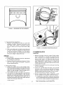
OIL SYSTEM
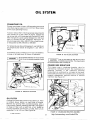
CRANKCASE OIL
Change crankcase oil every 100 operating hours and
only when engine is warm . (EXCEPTION : Drain initial
oil fill at 25 operating hours .)
To drain, remove the 1/2 inch cap screw (requiring 3/4
inch socket) on oil pan . After oil drains, replace the
cap screw and refill crankcase with 3 quarts (3 1/2 with
filter change) of a good quality detergentoil . Oil must
meet or exceed the API (American Petroleum Institute) designation SE or SE/CC ; this oil was formerly designated as MS, MS/DG or MS/DM .
For temperatures above 30 degrees F use SAE30 oil ;
for temperatures below 30 degrees F, use 10W or
5W30 .
In extremely dusty conditions or in very cold weather,
change oil at least every 50 hours of operation .
L
FIGURE 26 . OIL FILTER LOCATION
Do not overfill crankcase . Do not use service
DS oil . Do not mix brands nor grades of motor
oil .
CAUTION
Do not over-torque oil filter. Be sure ring is
installed around oil filter. This ring acts as an
air seal and prevents loss of cooling air .
CRANKCASE BREATHER
This engine uses a crankcase breather valve for
maintaining crankcase vacuum . No maintenance is
generally required . If the crankcase becomes
pressurized as evidenced by oil leaks at the seals,
clean baffle and valve in a suitable solvent . Crankcase
breather disassembly requires removal of exhaust
manifold . See Figure 27 .
FIGURE 25 . DIPSTICK LOCATION
OIL FILTER
Change the crankcase oil filter every 200 hours . Filter
is located above starter on right side of engine .
Remove by turning filter counterclockwise with a
filter wrench . Before installing new filter, coat gasket
on base of filter with a light film of oil . Install by
turning clockwise until friction is noted, then turn an
additional 1/4 to 1/2 turn . See Figure 26 .
FIGURE 27 . CRANKCASE BREATHER ASSEMBLY
© 2006 UsefulCDs
19
http://stores.ebay.com/UsefulCDs
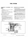
FUEL SYSTEM
CARBURETOR DISASSEMBLY
REPAIR
AND
CARBURETOR FLOAT ADJUSTMENT
1 . Invert float and casting .
2 . With the float resting lightly against the needle
and seat, there should be .07 to .11 inch clearance
between base of float and carburetor casting .
Removal :
1 . Disconnect fuel inlet hose and crankcase
breather hose .
2 . Remove air cleaner assembly .
A drill bit can be used for this measurement as shown in Figure 29 .
Use a 3/32 inch drill bit or any bit between .07 inch (No . 50) and .11
inch (No . 35) .
3 . Disconnect governor, throttle linkage, and choke
control .
4 . Remove two hold-down screws and lift carburetor
from intake manifold .
3 . If it is necessary to reset float level, remove the
float from carburetor and bend the float tang, near
the pin, to obtain correct float level .
Always work on carburetor in clean conditions .
Do not bend the float when installed; doing so
may cause deformation of needle or seat .
Replacing Needle and Valve Seat :
1 . Remove 7/16 inch hex at base of fuel bowl and lift
bowl from carburetor .
4 . Check the float closely for signs of leakage .
Repair or replace float if damaged or filled with
gasoline .
5 . Before assembling carburetor, remove filter
screen from float bowl and clean both screen and
base of float bowl .
6 . Install new gaskets when reassembling .
2 . Push out pin that holds float to carburetor body .
Disconnect spring holding needle to float .
3 . Remove float and set aside in a clean place . Pull
out needle and using a large screwdriver remove
needle valve seat .
4 . Install new valve seat and needle and replace
float .
5 . Adjust float .
CRANKCASE BREATHER HOSE
TO AIR INTAKE
IDLE ADJUSTMENT
ELECTRIC
FUEL PUMP
FUEL INLET
TO PUMP
FIGURE 28 . FUEL SYSTEM
© 2006 UsefulCDs
20
http://stores.ebay.com/UsefulCDs
CARBURETOR CLEANING AND INSPECTION
To clean the carburetor, soak all components
thoroughly in a good carburetor cleaner, following
the manufacturer's instructions . Be sure to remove all
carbon from carburetor bore, especially in the area of
the throttle valve . After soaking, clean out all
passages with filtered, compressed air .
Check the adjusting needles and nozzle for damage .
If float is loaded with fuel or damaged, replace it . The
float should fit freely on its pin without binding .
Check the choke and throttle shafts for excessive side
play and replace if necessary .
FIGURE 29 . CARBURETOR FLOAT ADJUSTMENT
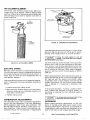
FUEL PUMP
Every 400 hours or sooner, drain fuel pump and check
filter element . Remove fuel pump mounting screws
and turn off hex nut on base of pump . If element
appears dirty, replace with a new one . Be sure to
replace gaskets when reassembling . Static fuel pump
pressure should be 21/2 to 31/4 psi .
FIGURE 31 . FUEL PUMP FILTER ELEMENT
FUEL SOLENOID
An electric fuel solenoid mounts between fuel pump
outlet and carburetor inlet . The solenoid opens
during cranking and running . A defective solenoid
will not allow plant to start . (Refer to Fuel System and
Control System Troubleshooting Guides .)
FIGURE 30 . EXPLODED VIEW OF CARBURETOR
© 2006 UsefulCDs
21
http://stores.ebay.com/UsefulCDs
AIR CLEANER ELEMENT
Check and clean element at least every 100 hours .
Loosen wing nut to remove . Clean by tapping base
lightly on a flat surface . Replace element at least every
200 operating hours ; clean or replace more often in
dusty conditions .
FIGURE 33 . CARBURETOR ADJUSTMENTS
have been disturbed turn main fuel jet 1-1/4 turn off its
seat and idle fuel jet one turn off its seat to permit
starting . Then readjust them for smooth operation .
Forcing the needle against its seat will
damage it . The needle does not completely
shut off fuel when turned fully in .
Set the throttle stop screw (located on the carburetor
throttle lever), with no load connected to the plant .
Turn stop so it just touches adjustment screw ; then
turn adjustment screw (with stop still touching it) until
unit is running at 1500 rpm . When stop is released,
governor will then control no-load speed at 1850 to
1890 rpm .
FIGURE 32 . AIR CLEANER ELEMENT
ELECTRIC CHOKE
Manually check movement of choke travel to be sure
it is not stuck open or closed . Voltage at choke should
be 12 volts during start and drop to zero during run . If
choke does not move at room temperature with 12
volts applied, replace it .
Before final adjustment, allow the engine to warm up .
Adjust the idle fuel jet with no load connected . Open
the main jet until the engine runs smooth under
acceleration with no load . Slightly more fuel may be
needed (open about 1/4 turn further) when sudden
load is applied or if operating in extremely cold
weather .
This choke should not require any seasonal readjustment . If adjustment becomes necessary proceed as
follows :
1 . Loosen choke lever clamp screw .
If the engine develops a "hunting" condition (alternate increase and decrease of engine speed), try
correcting by opening the main adjusting needle a
little more .
2 . With lever fully forward (away from carburetor),
adjust so choke valve is completely closed or not
more than 1/4 inch open .
3 . Tighten clamp screw .
Do not open main fuel jet more than 1/2 turn
beyond the maximum power point .
CARBURETOR ADJUSTMENTS
GOVERNOR
The carburetor has a main fuel (power) adjustment
and an idle fuel adjustment . The main adjustment
affects operation under heavy load conditions . The
idle adjustment affects operation under light or noload conditions . Under normal circumstances, adjustments should not be disturbed . If adjustments
© 2006 UsefulCDs
Before making governor adjustments, run the unit
about 15 minutes under light load to reach normal
operating temperature . (If governor is completelyout
of adjustment, make a preliminary adjustment at no
load to first attain a safe voltage operating range) .
22
http://stores.ebay.com/UsefulCDs
Engine speed determines the output voltage and
current frequency of the generator . By increasing the
engine speed, generator voltage and frequency are
increased, and by decreasing the engine speed,
generator voltage and frequency are decreased . An
accurate voltmeter or frequency meter (preferably
both) should be connected to the generator output in
order to correctly adjust the governor . A small speed
drop not noticeable without instruments will result in
an objectionable voltage drop . The engine speed can
be checked with a tachometer .
Linkage : The engine starts at wide open throttle . The
length of the linkage connecting the governor arm to
the throttle shaft and lever is adjusted by rotating the
ball joint . Adjust this length so that with the engine
stopped and tension on the governor spring, the stop
on the carburetor throttle lever just contacts the stop .
This setting allows immediate control by the governor
after starting . It also synchronizes travel of the
governor arm and the throttle shaft .
Speed Adjustment : With the warmed-up unit
operating at no load, adjust the tension of the
governor spring . Refer to
CHART and
RT(Figure 34) . Turn the speed adjusting
nut to obtain a voltage and speed reading within the
limits shown .
A binding in the bearings of the governor shaft, in the
ball joint, or in the carburetor throttle assembly will
cause erratic governor action or alternate increase
and decrease in speed (hunting) . A lean carburetor
adjustment may also cause hunting . Springs of all
kinds have a tendency to lose their calibrated tension
through fatigue after long usage . If all governor and
carburetor adjustments are properly made, and the
governor action is still erratic, replacing the spring
with a new one and resetting the adjustments will
usually correct the trouble .
VOLTAGE
SPEED
CHA
Sensitivity Adjustment: Refer to Figure 34 . Check the
voltage and speed, first with no load connected and
again with a full load . Adjust the sensitivity to give the
closest regulation (least speed and voltage difference
between no load and full load) without causing a
hunting condition .
1 . Adjust the carburetor idle needle with no load
connected .
To increase sensitivity (closer regulation), shift the
spring toward the governor shaft .
2 . Adjust the carburetor main jet for the best fuel
mixture while operating the set with a full rated
load connected .
3 . Adjust the length of the governor linkage and
check linkage and throttle shaft for binding or
excessive looseness .
4 . Adjust the governor spring tension for rated
speed at no load operation .
5 . Adjust the governor sensitivity .
An adjustment for too much sensitivity will cause
alternate increase and decrease of engine speed
(hunting) .
To decrease sensitivity, shift the spring toward the
outer end of the governor arm . Too little sensitivity
will result in too much difference in speed between no
load and full load conditions .
6 . Recheck the speed adjustment .
7 . Set the carburetor throttle stop screw .
Any change in the sensitivity adjustment usually
requires a compensating speed (linkage) adjustment .
THR )T LE
?SOP ` .E,:RcW
VOLTAGE CHART
FOR CHECKING
GOVERNOR REGULATION
MAXIMUM
NO-LOAD VOLTAGE
MINIMUM
FULL-LOAD VOLTAGE
LINKAGE
An IusrMiENT
----I
LOOSEN
Fi
LASS
SPEED
r-tuT-
120 VOLT
1 PHASE
2 WIRE
TIGHTr_N N'UT
FOR MORF
SPEED
126
110
SPEED CHART FOR CHECKING
GOVERNOR REGULATION
MAXIMUM NO-LOAD SPEED (RPM)
HERTZ (CURRENT FREQUENCY)
MINIMUM FULL-LOAD SPEED (RPM)
HERTZ
GOVERNOR
ARM
1890
63
1770
59
FIGURE 34. GOVERNOR ADJUSTMENTS
© 2006 UsefulCDs
23
http://stores.ebay.com/UsefulCDs
FUEL SYSTEM TROUBLESHOOTING GUIDE
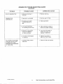
TROUBLE
FUEL LEAKS FROM
CARBURETOR
ENGINE SMOKES AND
RUNS RICH
© 2006 UsefulCDs
CAUSE
REMEDY
1 . Float level set
too high
1 . With fuel bowl removed
and carburetor inverted,
set float parallel to
bowl flange
(3/32" clearance)
2 . Dirt under inlet
valve
2 . Remove inlet valve, clean
seat by rinsing in clean
fuel and blow off with
compressed air
3 . Bowl vent plugged
3 . Remove bowl and blow
clean with compressed
air
4 . Collapsed float
caused by blowing
assembled carburetor
with compressed air
4 . Replace float
5 . Carburetor gummed
from storage .
Float stuck to screen
5 . Remove fuel bowl and
clean with suitable
solvent .
1 . Dirty air filter
1 . Clean or replace
2 . Improper adjustment
2 . Set idle and power needles
at one turn open . After
engine starts and runs,
set for optimum
performance
3 . Nozzle boss gasket
leaks . Engine runs
with power needle
seated
3 . Remove fuel bowl and
replace gasket . Tighten
bowl retainer securely .
4 . Air bleeds in
carburetor plugged
4 . Remove fuel bowl, idle
and power needles . Clean
thoroughly with compressed
air .
24
http://stores.ebay.com/UsefulCDs
FUEL SYSTEM TROUBLESHOOTING GUIDE
(Continued)
TROUBLE
ENGINE RUNS LEAN
ENGINE STARTS HARD
GOVERNOR SURGE
© 2006 UsefulCDs
I
CAUSE
REMEDY
1 . Improper adjustment
1 . Set idle and power needles
at one turn open . After
engine starts and runs,
set for optimum performance
2 . Idle holes plugged .
Dirt in fuel delivery
channels
2 . Remove fuel bowl, idle and
power needles . Clean
thoroughly with compressed
air
3 . Float level set too
low . Low level in
fuel bowl
3 . With fuel bowl removed
and carburetor inverted,
set float parallel to bowl
flange (3/32" clearance)
4 . Fuel filter in electric
fuel pump dirty
4 . Remove filter and replace
5 . Fuel filter (screen) in
bowl plugged
5 . Remove fuel bowl .
Clean thoroughly and replace
1 . Improper adjustment
1 . Set idle and power needles
at one turn open . After
engine starts and runs, set
for optimum performance
2 . No fuel in carburetor
2 . Check carburetor drain valve .
If no fuel in bowl, clean tank
filter and carburetor . Check electric
fuel pump operation . Check
electric solenoid valve .
3 . Choke valve not
closing
3 . Check controls for proper
travel
Throttle shaft and
valve binding
Remove and replace shaft if
worn . Clean carburetor body .
Reassemble throttle shaft
assembly into carburetor body
as far as possible . Hold
firmly in place in this
position while assembling
throttle valve . Make
certain valve does not bind
in throttle bore when
opening and closing throttle .
25
http://stores.ebay.com/UsefulCDs
IGNITION AND BATTERY CHARGING
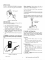
BREAKER POINTS (Cold Setting)
The engine is equipped with an automotive type
battery ignition system . Both spark plugs fire
simultaneously, thus the need for a distributor is
eliminated . Spark advance is set at 26 degrees BTC
(before top center) and should be maintained for best
engine performance . Always check timing after
replacing ignition points or if noticing poor engine
performance . Proceed as follows :
To maintain maximum efficiency from the engine,
change the breaker points every 200 hours of operation . Proceed as follows :
1 . Remove the two screws and the cover on the
breaker box .
2 . Remove the two spark plugs so engine can be
easily rotated by hand . Check condition of spark
plugs at this time .
Timing Procedure - Engine Not Running - Cold
Setting
3 . Refer to Figure 35 . Remove mounting nut (A) and
pull the points out of the box just far enough so
screw (B) can be removed and leads disconnected .
4 . Remove screw (C) and replace condenser with a
new one .
5 . Replace points with a new set but do not completely tighten mounting nut (A) .
6 . Remove the dot button on blower housing . This
provides an access to view timing mark .
7 . Rotate the engine clockwise (facing flywheel) by
hand until the 26 degree BTC mark on gear cover
aligns with mark on flywheel . Turn another 1/4
turn (90 degrees) to ensure points are fully open .
8 . Using a screwdriver inserted in notch (D) on the
right side of points, turn points until gap
measures .025 inch with a flat thickness gauge .
(Be sure feeler is clean .) Tighten mounting screw
and recheck gap .
1 . Connect a continuity test lamp set across the
ignition breaker points . Touch one test prod to
the breaker box terminal to which the coil lead is
connected and touch the other test prod to a good
ground on the engine .
2 . Turn
crankshaft against
rotation
(counterclockwise) until the points close . Then slowly
turn the crankshaft with rotation (clockwise) .
3 . The lamp should go out just as the points break
which is the time at which ignition occurs (26
degrees BTC) .
Timing Procedure - Engine Running - Hot Setting
1 . To check the ignition timing with unit running use
a timing light . Connect the timing light according
to its manufacturer's instructions . Either spark
plug can be used as they fire simultaneously .
2 . Remove the dot button on blower housing to
provide an access to view timing marks .
3 . Start the engine and check the timing . The mark
on the flywheel should line up with the 21 degree
mark on the cover when engine is warmed up .
4 . Replace dot button, breaker box cover and any
other hardware removed from engine .
9 . Check ignition timing .
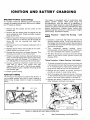
IGNITION TIMING
The timing on the engine is preset at the factory . A
non-movable breaker point box is used, however a
slight timing change could be made by adjusting
points .
-r
I
0
- DOT DUTTON
(ACCLSS TO
TIMING MARK
FIGURE 35 . BREAKER BOX AND TIMING ACCESS HOLE
© 2006 UsefulCDs
26
http://stores.ebay.com/UsefulCDs
SPARK PLUGS
Remove hnth spark plugs and install new ones every
250 hours . Use Onan No . 167-0245 or equivalent .
Check to be sure spark plug gap is set at .020 inch .
Battery Inspection : Check battery cells with a
hydrometer . The specific gravity reading should be
approximately 1 .280 at 80 degrees F .
If one or more cells are low on water, add distilled
water and recharge .
Keep the battery case clean and dry . An accumulation
of moisture will lead to a more rapid discharge and
battery failure .
Keep the battery terminals clean and tight . After
making connections, coat the terminals with a light
application of petroleum jelly or grease to retard
corrosion .
FIGURE 36 . SPARK PLUG GAP
IGNITION COIL
To test primary and secondary windings within the
ignition coil proceed as follows :
1 . Use a Simpson 260 VOM or equivalent .
2 . Place black lead on ground (-) terminal of coil and
red lead to positive (+) terminal . Primary
resistance should read 4 .30 (±10%) ohms .
3 . Change resistance setting on ohmmeter . Place
ohmmeter leads inside spark plug cable holes
(Figure 37) . Secondary resistance should read
14,000 (±10%) ohms .
4 . If any of the above conditions are not met, replace
coil .
FIGURE 38 . SPECIFIC GRAVITY TEST
FLYWHEEL ALTERNATOR
This unit is equipped with a permanent magnet
flywheel alternator and solid-state voltage regulatorrectifier (output control) . As with all solid-state
electrical units, precautions are necessary when
servicing . Observe the following .
This engine uses a 12 volt, negative ground
system . Alternator must be connected to
battery at all times when engine is running . Do not reverse battery
cables .
Precautions :
1 . Do not connect battery cables in the wrong
polarity .
2 . Do not short together alternator stator leads .
3 . Do not run without a battery . Damage will occur
to regulator and battery ignition coil .
Preservice Checks :
1 . Check for a good ground between equipment and
regulator-rectifier case .
2 . Be sure output control plug (connector) is
properly inserted into stator receptacle to
eliminate any resistance due to a poor connection . Keep it clean and tight .
3 . Check battery and its connection to be sure it is
serviceable .
Charging system tests require a fully charged
battery .
FIGURE 37 . TESTING COIL
© 2006 UsefulCDs
27
http://stores.ebay.com/UsefulCDs
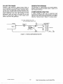
TESTING BATTERY CHARGING SYSTEM
BASIC TEST
PROCEDURE
TEST VALUES
1 . Battery
Battery Voltage - unit not running
2 . Regulator
Battery Voltage after unit is
running 3 to 5 minutes .
3 . Alternator
Stator and
Wiring with
Fully Charged
battery .
Ohmmeter reading from stator
output - unit not running .
Disconnect wire terminating at
AC terminal of voltage regulator
and wire terminating at BAT
terminal of start solenoid . Insert
ohmmeter between these wires .
4 . Alternator
Stator and
Wiring
Measure AC stator output voltage
with unit running . Disconnect
wire terminating at AC terminal
of voltage regulator . Measure
AC voltage (unit running) between
this wire and BAT terminal of
start solenoid .
12 VDC
13 .6 to 14 .7 VDC
.2 to .6 Ohms
28 VAC
FIGURE 39. FLYWHEEL ALTERNATOR
© 2006 UsefulCDs
28
http://stores.ebay.com/UsefulCDs
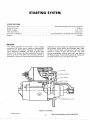
STARTING SYSTEM
SPECIFICATIONS
Engaging System
Nominal Output
Rated Voltage
Field Connection
Direction of Rotation
Weight
Solenoid-operated Overrunning Clutch
0 .68 Hp
D .C . 12 V .
Compound
Counterclockwise (Viewing from pinion end)
6 .76 lbs .
DESIGN
The starter consists of two parts : a low voltage
compound DC motor and a means of transmitting
motor power to the flywheel ring gear . The constructional difference between this type of starter and
others is that the lever spring is located in the central
portion of the front bracket . The shift lever, which is
operated by solenoid, causes the overrunning clutch
assembly to move along the armature shaft toward
the flywheel . As the pinion and flywheel teeth make
contact, the shift lever continues to move and make
electrical contact to spin the armature . The lever
spring compresses, holding the pinion gear against
the flywheel gear . As soon as the armature rotates and
the gear teeth line up, the gears will mesh .
PLUNGER
SPRING HOLDER
LEVER SPRING
SHIFT LEVER
OVERRUNNING CLUTCH
FIGURE 40 . STARTER
© 2006 UsefulCDs
29
http://stores.ebay.com/UsefulCDs
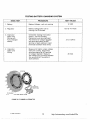
STARTER REMOVAL
6 . Disconnect heavy wire that connects to starter .
7 . Remove two starter hold-down studs and lift out
starter .
Starter removal requires removal of the generating set from its slide
rails and mounts .
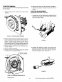
STARTER DISASSEMBLY
1 . Remove blower scroll from front of engine (four
screws) .
Disassemble the starter as follows :
1 . Loosen the nut that attaches the solenoid motor
terminal to the field coil connector lead and take
off the connector lead .
FIGURE 41 . BLOWER SCROLL REMOVED
2 . Remove flywheel with a flywheel puller or loosen
center cap screw and direct a sharp blow to
loosen . It helps to pull forward on one side of
flywheel when striking with a hammer . If using
this procedure be sure to leave center cap screw
loosely in place or blower wheel will fall on floor .
3 . Remove left and right hand air shrouds that cover
cylinder heads .
4 . Remove exhaust manifold .
5 . Remove blower scroll backing plate (two screws
on bottom - two on gear cover) .
FIGURE 43 .
2 . Loosen the retaining screws and remove the
solenoid from the front bracket . Simultaneously,
the fiber washers, the return spring and the
solenoid plunger will be removed .
FIGURE 42 . REMOVING BACKING PLATE
© 2006 UsefulCDs
30
http://stores.ebay.com/UsefulCDs
3 . Unscrew the through bolts and separate the yoke
with the rear bracket from the front bracket .
5 . Removing the insulated brush from the brush
holder permits separation of the rear bracket from
the yoke .
FIGURE 45
FIGURE 47
4 . Remove the armature from the front bracket .
Simultaneously, the shift lever, the lever spring
and the spring holder will be removed .
6 . If it is necessary to remove overrunning clutch,
first, put a metal cylinder of suitable size over the
end of armature shaft so it rests on the stop ring .
Then tap the cylinder lightly with a hammer, the
stop ring towards armature and lock ring . Remove
ring from groove in shaft so the overrunning
clutch and the stop ring will be removed from the
armature shaft .
CLEANING PARTS
1 . Do not immerse parts in cleaning solvent .
Immersing the field coil, yoke assembly,
armature and solenoid will damage the insulation . Wipe these parts
with a cloth only .
2 . Do not immerse the overrunning clutch in cleaning solvent . The
clutch is prelubricated at the factory, and solvent will wash lube
from clutch .
FIGURE 46
3 . Wash all other parts in solvent and dry the parts .
BRUSH
SPRING
I
BRUSH (-)
REAR BEARING
SCREW
I
(BRUSH
WASHER
(+)
YOKE
REAR
SET
.
BRACKET
ASSY
ASSY .
I
ARMATURE
FRONT
BRACKET
ASSY .
FIGURE 48 . EXPLODED VIEW OF STARTER
© 2006 UsefulCDs
31
http://stores.ebay.com/UsefulCDs
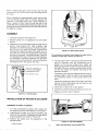
INSPECTION OF PARTS
Commutator Runout : Place armature in a pair of vblocks and measure runout with a dial indicator .
Measure both shaft and commutator . A bent shaft
requires replacement of armature . When runout exceeds
.004 inch, commutator should be refaced .
Remove only enough metal to provide a smooth, even
surface .
Grounded Armature : Use a 120 volt test lamp set for
testing armature for grounds . If lamp lights when one
probe of test lamp is touched to commutator with
other probe to the core, the armature is grounded and
must be replaced .
IF ARMATURE IS GOOD
LAMP SHOULD NOT LIGHT
FIGURE 51 . CHECKING COMMUTATOR RUNOUT
FIGURE 49 . TESTING FOR GROUNDED ARMATURE
Open Field Coil : Use a 120 volt test lamp set for this
test . Connect one probe of test lamp to the yoke and
the other probe to insulated brush . If lamp does not
light, the field coil is open .
Shorted Armature : Use a growler tester for testing
armature for a short circuit . Place armature in growler
and hold a thin, steel blade (hacksaw blade) parallel
to the core and just above it while slowly rotating
armature in growler . A shorted armature will cause
blade to vibrate and be attracted to the core .
This starter is compound wound, having a series coil and a shunt
coil . The grounded end of the shunt coil is soldered inside of the
yoke .
Grounded Field Coil : Use a 120 volt test lamp set for
testing for a grounded field coil . First disconnect the
grounded end of shunt coil as shown in Figure 52 .
Then connect one probe of test lamp to yoke and the
other probe to field coil connector lead . If lamp lights,
field coil is grounded .
UNSOLDER THE GROUNDED END OF
SHUNT COIL-(DO NOT DISCONNECT
THE RIVETED JOINT)
FIGURE 50 . TESTING FOR A SHORT CIRCUIT
Open Armature : The most likely place to check for an
open circuit is at the commutator riser bars . Inspect
for loose connections on points where the conductors are joined to the commutator bars .
© 2006 UsefulCDs
FIGURE 52
32
http://stores.ebay.com/UsefulCDs
BRUSH REPLACEMENT
REASSEMBLY
Brushes that are worn out to the wear limit line should
be replaced . Brushes can be replaced after removing
the rear bracket .
Reassembly is the reverse of disassembly . Note the
following :
1 . Lubricate armature shaft and splines with a very
light grade oil . A medium or heavy oil and grease
may cause faulty operation in cold weather .
When resoldering the brushes, make a low resistance
connection, using a high temperature solder and
resin flux .
T
/4
1/2
2 . Install the overrunning clutch assembly, the ring
and the stop ring on the armature shaft . Drive
pinion stopper far enough on shaft to install stop
ring . Then using a puller (Figure 55) pull stopper
against ring .
WEAR
LIMIT
LINE
FIGURE 53 . BRUSH WEAR LIMIT
FIGURE 55
Brush Springs : The spring tension should be taken
using a push-type spring scale until the top of a new
brush protrudes 1/16 inch from the brush holder .
Spring tension should be 36 to 48 ounces . See Figure
54 .
Overrunning Clutch : The pinion gear should rotate
smoothly in one direction (not necessarily easily), but
should not rotate in opposite direction . If pinion gear
does not function properly, or if pinion gear is worn or
burred, replace the overrunning clutch .
3 . Apply a small amount of lubriplate on the shift
lever pivot pin and lever holders .
Install the shift lever over the clutch assembly with
position indicated in Figure 56 . This is important,
if the shift lever is not properly positioned the
pinion gear travel will be restricted causing a
locking in the clutch mechanism .
FIGURE 54 . CHECKING BRUSH SPRING TENSION
FIGURE 56
© 2006 UsefulCDs
33
http://stores.ebay.com/UsefulCDs
4 . Place the thrust washer on the drive end of the
shaft . Slide the armature with the lever into the
front bracket .
8 . Insert two brushes and springs in their brush
holders and push them against spring tension .
Secure the brushes by iron wires as shown in
Figure 61 .
FIGURE 57
5 . Place the lever spring and the spring holder into
the front bracket with the direction shown in
Figure 58 .
a
TO FRONT BRACKET
FIGURE 61
01a)"we
9 . When securing the brushes, position the rear
bracket to the yoke, inserting the rubbergasketto
the slot of the rear bracket . After the rear bracket
is installed to the yoke, withdraw iron wires so the
brushes and the commutator come in contact .
Then, insert the bushings into the holes to keep
out dirt.
FIGURE 58
6 . Position the Yoke to the front bracket . Be sure
that the yoke is properly indexed to the front
bracket .
10 . Fasten through bolts securely .
11 . Install the solenoid plunger over the top of the
shift lever in the front bracket . Be sure that the
pinion gear is moved when the plunger is pulled
manually .
FIGURE 59
7 . Place the thrust washer (steel) and washer (fiber)
on the commutator end of shaft, and apply a small
amount of lubriplate on the shaft .
In case three washers are used, the fiber washer is placed between
the steel washers.
FIGURE 62
12 . Install the solenoid .
The return spring, in this case, should be
straight in the proper position between the
bore of the solenoid and the bore of the plunger.
FIGURE 60
© 2006 UsefulCDs
34
http://stores.ebay.com/UsefulCDs
TESTING AND ADJUSTING
Adjusting Pinion Clearance : After the starter is
reassembled the pinion clearance must be adjusted to
give sufficient clearance between the end of the
pinion and the stop ring when the pinion is in mesh
with the ring gear of the engine .
No Load Test : For this test connect starter as shown in
Figure 63 . The values of this test should be as follows :
Battery Voltage11 .5 Volts
Minimum RPM6000 RPM
Maximum Current Draw . . . 55 Amps
1 . Connect a battery of the proper voltage between
the "Switch" terminal of the solenoid and the
bracket of the starter (ground), so the pinion will
travel .
1 . Before installing the starter, be sure starter
and engine mounting surfaces are free of dirt
and oil . These surfaces must be clean to make a good electrical
contact .
2 . Then, push the pinion back until play is taken out
of the lever and the clutch mechanism .
2 . Don't operate the starter more than 30 seconds, or serious
damage may result . Starters are not designed for continuous
operation .
3 . Measure the pinion clearance .
4 . The clearance should be 0 .002 to 0 .008 inch .
Adjust by removing the solenoid and increasing
or decreasing the number of the fiber washers .
3 . When the engine does not rotate, don't hold the starter in a stall
condition more than 10 seconds .
Increasing the number of the washers decreases clearance, and
decreasing the number of the washers increases clearance .
4 . The wires between the battery and the starter should be of
sufficient size to carry the electric load without excessive voltage
drop.
SWITCH
FIGURE 63
© 2006 UsefulCDs
35
http://stores.ebay.com/UsefulCDs
AC GENERATOR MAINTENANCE
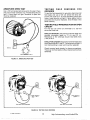
GENERAL
Note that brush blocks are stamped "BRG END" on
one side . Be sure this stamped side faces bearing end
of generator for correct brush alignment . Tighten the
brush block screws to 40-70 in-lb . (4-6 ft-lb .) . If some
sparking occurs after replacing brushes, run the plant
with a light load until brushes seat properly . Check
brush springs for freedom of movement .
The generator uses a revolving armature and normally needs little care other than a periodic check of the
brushes and collector rings . If a major generator
repair becomes necessary, have the equipment
checked and tested by a qualified electrician who is
thoroughly familiar with the operation of electric
generating equipment .
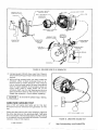
GENERATOR DISASSEMBLY
All accessories must betaken off and power plant must be removed
from its slide rails for disassembly and repair of the generator .
1 . Remove power plant from its slide rails .
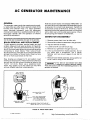
BRUSH REMOVAL AND REPLACEMENT
2 . Remove all accessories attached to the generator .
3 . Tag and remove all leads .
4 . Loosen and lift out both brush rigs .
To gain access to brushes, remove plastic end bell
screens . Measure brush wear as shown in Figure 64,
using a small, narrow scale inserted into top of brush
block . If brushes need replacing remove and tag wires
connecting to brush blocks . Then remove brush
blocks and lift out of end bell . Pull out the brushes and
springs from bottom of brush block . Clean out any
dirt or oil from brush block at this time .
5 . Remove four generator through-stud nuts .
6 . Lift or pull end bell from frame assembly . Do not
pry loose with a screwdriver, use a plastic
hammer and tap around edges of end bell to
loosen .
7 . Remove frame (field) assembly, being careful not
to let it rest or drag on the armature .
New brushes are shaped to fit and seldom need
sanding to seat properly . Always replace brushes as a
set and use only the correct brushes as listed in the
PARTS CATALOG. Never use a substitute brush
which may appear to be the same but may have
entirely different electrical characteristics .
Four seals are used between frame (field)
assembly and engine-to-generator adapter .
These seals must be used when reassembling generator or the
generator will overheat.
TOP VIEW OF
BRUSH BLOCK
O
O
~O
C;_13 O
C
BR o END
O
O,
MAXIMUM WEAR LIMIT
ONE INCH
REPLACE WHEN WORN
TO THIS DIMENSION
OR IF MEASUREMENT
"A" EXCEEDS ONE INCH
CROSS SECTION OF
BRUSH BLOCK
NOTE . MEASURE FROM TOP FACE OF
BRUSH BLOCK TO TOP OF BRUSH .
FIGURE 64 . BRUSH WEAR LIMITS
© 2006 UsefulCDs
36
http://stores.ebay.com/UsefulCDs
ARMATURE (ROTOR)
THROUGH-STUD
GENERATOR-TOADAPTER SEALS
BALL BEARING & CLIP
ROLL PIN
f
ARMATURE
ASSEMBLY
GROMMET FOR
OUTPUT LEADS
BRIDGE
RECTIFIER
ASSEMBLY
END BELL
FIGURE 65 . EXPLODED VIEW OF AC GENERATOR
8 . Using a square 3/8 inch drive, insert into 12-point
(internal wrenching) armature hold-down nut and
remove .
9 . While pulling outward with one hand under the
armature, strike a sharp end-wise blow on armature shaft to loosen armature . The armature
has an internal taper which fits onto the external
taper of engine adapter . If the armature does not
come loose, place a heavy brass rod on the
armature shaft near the ball bearing and strike a
sharp downward blow on the rod with a hammer .
Rotate the armature 1/2 turn before repeating .
Do not strike the collector rings or bearing .
ARMATURE GROUND TEST
Use a 120 volt series test lamp set for this test .
Armature must be removed from generator for this
test .
Place one test prod on one of the collector rings and
the other test prod on the armature shaft . Test lamp
should not light . If the test lamp lights, the AC winding
or a collector ring is grounded to the shaft . Test both
collector rings in this manner .
© 2006 UsefulCDs
FIGURE 66 . ARMATURE GROUND TEST
37
http://stores.ebay.com/UsefulCDs
ARMATURE OPEN TEST
TESTING
GROUNDS
Use a 120 volt series test lamp set for this test . Place
one prod on each collector ring . Thetestlamp should
light . If lamp does not light, armature is open and
must be replaced .
FIELD WINDINGS
FOR
To test the field assembly for grounds, disconnect all
field leads and use a 120 volt series test lamp set .
Touch one prod to F1 (+) and the other prod to the
frame . Lamp should not light . If lamp lights, field is
grounded and must be replaced . (Test F2 lead in the
same manner .)
TESTING FIELD WINDINGS FOR AN OPEN
CIRCUIT
For this test use either an ohmmeter or a 120 volt
series test lamp set .
Using an Ohmmeter : Disconnect external leads and
connect ohmmeter leads to F1 (+) and F2 (-) .
Resistance in the windings should read 28 .8 ohms
(±3%) at 70 F .
Using a Test Lamp Set: Disconnect external leads and
touch test prods to F1 and F2 . The lamp should light . If
not, field winding is open and must be replaced .
Check terminal ends closely for loose connections .
These can be fixed easily without replacing the whole
assembly .
FIGURE 67. ARMATURE OPEN TEST
B11o
B11OA
F2
LAMP SHOULD
NOT LIGHT
LAMP SHOULD
LIGHT
TESTING FOR GROUNDS
TESTING FOR OPENS
FIGURE 68 . TESTING FIELD WINDINGS
© 2006 UsefulCDs
38
http://stores.ebay.com/UsefulCDs
LOAD WIRES
X I LEAD
FIGURE 69 . END BELL ASSEMBLY
TESTING BRIDGE RECTIFIER
To accurately test bridge rectifier proceed as follows :
6 . If any tests do not agree with the above readings,
install a new bridge rectifier .
1 . Loosen No . 8-32 screw to remove bridge rectifier
assembly (see Figure 69 for location) .
2 . Disconnect the nylon connector from bridge
rectifier assembly, noting the polarity marking of
bridge rectifier assembly and connector .
3 . Pull out from end bell and remove bridge rectifier
from its case .
All terminals are marked on both bridge
rectifier and nylon case . Observe proper
polarity when reinstalling . If installed wrong, generator voltage will
not build up .
NOTE : RED MARK APPEARS
NEAR "+" LEAD
Note that connector can only be mounted in
the end bell one direction, but the bridge
rectifier can be mounted in (4) four directions of which only one will
work .
4 . Use an ohmmeter to test bridge rectifier . Set the
ohmmeter dial to R x 1 scale .
5 . Now place meter leads on points shown in Figure
70 and note readings from Table below .
OHMMETER
BLACK LEAD *
OHMMETER
RED LEAD *
RESISTANCE
A
A
B
D
B
D
C
C
B
D
C
C
A
A
B
D
* 8 ohms
* 8 ohms
* 8 ohms
* 8 ohms
Infinity
Infinity
Infinity
Infinity
TOP VIEW
AC
.
6
I•
AC /
SCHEMATIC
FIGURE 70 . TESTING BRIDGE RECTIFIER
± 10% - Readings taken at 70 F .
© 2006 UsefulCDs
39
http://stores.ebay.com/UsefulCDs
COLLECTOR RINGS
GENERATOR BEARING
Collector rings acquire a glossy brown finish in
normal operation . Do not attempt to maintain a bright,
newly machined appearing surface . Ordinary cleaning with a dry, lint-free cloth is usually sufficient . Very
fine sandpaper (#240 or finer) may be used to remove
slight roughness . Use only light pressure on the
sandpaper, while the plant is running . Do not use
emery or carborundum paper or cloth . Clean out all
carbon dust from the generator .
The generator is prelubricated and double-sealed .
Replace bearing approximately every 5 years or at
each engine overhaul .
COMPOUNDING REACTOR
If output voltage is high with no electrical load
connected to the generator, with generator running at
1800 rpm, then the compounding reactor is probably
defective . Test as shown in Figure 71, using a variac .
WITH ONE AMPERE INPUT THE
VOLTAGE SHOULD READ 65-75
FIGURE 71 . TESTING COMPOUNDING REACTOR
© 2006 UsefulCDs
40
http://stores.ebay.com/UsefulCDs
END BELL
REACTOR
H1
H2
CIRCUIT PROTECTOR
1
H3
1
1
--~LOAD LEADS
LOAD
1
GRD-L2
1
1
I
1
1
O
L1
AC
GR D-L2~-o
+
F2
BRIDGE RECTIFIER
FIGURE 72 . AC GENERATOR SCHEMATIC
GENERATOR VALUES FOR 4KW
MODEL
4KW
TYPICAL
TYPICAL
N .L . VOLTS
N .L . VOLTS
N .L . VOLTS
F .L . VOLTS
X1 to H1
F1 to F2
RESISTANCE RESISTANCE
F1 to F2
H1 to X1
FULL LOAD
CURRENT
125
112
100 VAC
40V DC
28 Ohms
0 .83 Ohms
33 Amps
N .L . - No Load
F .L . - Full Load
GENERATOR TORQUE VALUES
DESCRIPTION
Generator Through Studs (4)
Armature Holddown Nut - 12 Point
Compounding Reactor Studs
Brush Block Assembly Studs
© 2006 UsefulCDs
41
TORQUE VALUE
15-18
45-50
4- 6
4- 6
http://stores.ebay.com/UsefulCDs
Ft .-Lb .
Ft .-Lb .
Ft .-Lb .
Ft .-Lb .
GENERATOR TROUBLESHOOTING GUIDE
TROUBLE
NO AC OUTPUT
VOLTAGE
LIGHTS FLICKER
INTERMITTENTLY
LOW AC OUTPUT
VOLTAGE
© 2006 UsefulCDs
POSSIBLE CAUSE
CORRECTIVE ACTION
1 . Blown fuse or
circuit breaker .
1 . Replace fuse or reset
breaker and look for cause .
2 . Disconnected wire or
lead on brushes,
bridge rectifier or
reactor assembly .
2 . Reconnect wire or wires .
3 . Brushes not making
contact with collector
rings .
3 . Check brush springs for
free movement or brushes
which may be excessively
worn .
4 . Open, grounded or
short circuit in
field or armature
winding .
4 . Test with series test
lamp and repair or replace
as necessary .
5 . Defective bridge
rectifier assembly .
5 . Test with ohmmeter and
replace if defective .
6 . Bridge rectifier
assembly installed
wrong in its case .
6 . Reinstall making sure
marks on case and rectifier
match .
1 . Loose or broken lead/
leads in generator .
1 . Repair broken lead or
reconnect loose lead .
2 . Brushes stuck in holder.
2 . Loosen brush and clean
or turn rings in lathe .
1 . External short circuit
on line .
1 . Locate and eliminate short
circuit problem .
2 . Generator overloaded .
2 . Remove part of load .
3 . Shorted or grounded
circuit in field or
armature winding .
3 . Test with series test lamp
or ohmmeter and replace if
defective .
4 . Engine not running
properly causing generator to slow down .
4 . Refer to Engine Troubleshooting guide .
42
http://stores.ebay.com/UsefulCDs
GENERATOR TROUBLESHOOTING GUIDE
(Continued)
TROUBLE
POSSIBLE CAUSE
CORRECTIVE ACTION
NOISY GENERATOR
1 . Defective bearing in
end ball .
1 . Replace bearing .
GENERATOR
OVERHEATS
1 . Generator overloaded .
1 . Remove part of load .
2 . Windings and parts
covered with oil or
dirt .
2 . Clean generator .
3 . Air intake restricted
or incoming air too hot .
3 . Take necessary steps to
allow for proper cooling .
4 . Shorted or grounded
circuit in armature
or field windings .
4 . Test with ohmmeter or
series test lamp and
replace if defective .
5 . Air seals are damaged
or missing .
5 . Replace air seals or
tape over the air leak .
1 . Compounding reactor
defective .
1 . Remove, test and replace .
AC OUTPUT VOLTAGE
HIGH WITH NO LOAD
CONNECTED AND
GENERATOR RUNNING
AT 1800 RPM
© 2006 UsefulCDs
43
http://stores.ebay.com/UsefulCDs
CONTROLS
THEORY OF OPERATION
Starting
FUSE PROTECTION
To start, push start switch S3 . Battery current flows
through K1 solenoid, K2 contacts and start switch S3
to battery negative (GND) . K1 solenoid closes contacts, feeding current to starter motor and to choke El
plus K3 relay . K3 relay contacts close the circuit to the
ignition coil T1 and fuel pump E2 plus fuel solenoid
K4 . The engine cranks and the fuel pump, fuel
solenoid and ignition operate to start the engine .
A 5 amp fuse, installed on control board, protects the
board from shorts in the remote wiring . If fuse is
blown it can be replaced (after correcting trouble) by
removing cover on control and replacing with an
identical 5 ampere fuse .
Engine Starts
When the engine starts and rpm increases, the
flywheel alternator develops a voltage which is rectified and energizes relay K2 . Relay K2 contacts close
to hold relay K3 energized, and K2 normally closed
contacts open to drop K1 start solenoid . K3 contacts
maintain current to ignition coil, fuel pump and fuel
solenoid . The engine runs and K2 remains energized .
CONTROL
START
Stop Engine
Relay K3, energized by K2, maintains ignition . To stop
engine, push the stop switch which shorts out K3 .
Relay K3 drops out to remove power from the fuel
pump, fuel solenoid and ignition coil . Resistor R2
absorbs the power that was supplied to K3 during the
period the stop switch is held closed as the engine
slows to a stop .
STOP
I
5 AMP FUSE
(REMOVE COVER
TO REPLACE)
Low Oil Pressure Shutdown
The control has a time delay of 2 to 4 seconds for a low
oil pressure shutdown . If a low oil pressure condition
occurs, the low oil pressure switch S2 closes to
charge capacitor C3 through resistor R3 . When the
voltage on capacitor C3 matches the voltage of the
divider R5-R6, the programmable unijunction transistor Q1 "fires" to trigger CR8 . CR8 turns on to deenergize K3 relay . K2 contacts open as the engine
stops and CR8 turns off .
Onan
ELECTRIC POWER
EMERGENCY START-STOP OPERATION
In an emergency, the control board can be bypassed
to start or stop the unit . Connect a jumper between
terminals 9 and 11 to energize the ignition, fuel
solenoid and fuel pump . Then temporarily jumper
terminals 1 and 7 to energize starter . Remove this
jumper as soon as the engine starts and r uns . D O
NOT jumper while engine is running . To stop, remove
the jumper from terminals 9 and 11 .
8134
FIGURE 73 . FUSE LOCATION
This emergency operation DOES NOT
provide fuse protection, start disconnect or
low oil pressure shutdown and should not be used without
monitoring the electric power plant .
© 2006 UsefulCDs
44
http://stores.ebay.com/UsefulCDs
SCHEMATIC
BTI
~LI
BI
PAC
VRI
S1Breaker Box
S2Low Oil Pressure Switch
S3Start-Stop Switch
T1Ignition Coil
VR1Voltage Regulator
RTMRunning Time Meter (Opt .)
BCM . Battery Condition Meter (Opt .)
K4Fuel Solenoid
B T1 Battery
B1
Starter
ElElectric Choke
E2Fuel Pump
E3, E4Spark Plugs
F15 amp . Fuse
G1Battery Charging Alternator
K1Start Solenoid
FIGURE 74 . CONTROL SYSTEM SCHEMATIC
© 2006 UsefulCDs
45
http://stores.ebay.com/UsefulCDs
CONTROL SYSTEM TROUBLESHOOTING GUIDE
This troubleshooting section is divided into four
parts, A, B, C and D as follows :
A.
B.
C.
D.
Always stop the power plant and disconnect the battery leads
before removing the cover or printed circuit board. After removing
control cover, use a long nose pliers to remove flag connectors
from terminals on board. Pull flag connectors straight out to avoid
breaking control board terminals . Although dust covers on two
relays (K2 and K3) are removable, DO NOT attempt to adjust the
contacts on these relays ; they are precision set at the factory . The
only maintenance required on these relays is blowing out sand and
dirt with a low pressure, compressed air source .
Engine does not crank .
Engine cranks but does not start .
Engine runs for 3 or 4 seconds, then stops .
Low battery - low charge rate .
To correct a problem, answer the question of the step
either YES or NO . Then refer to the number in
whichever column question was answered, and
proceed to that step next .
A.
ENGINE DOES NOT CRANK
YES
NO
1A .
Check battery . Are battery terminals clean and are
cables tight?
2A
---
Check battery cables for correct polarity . Is
12 volts present across battery terminals with
engine stopped and is 8 volts or higher present
with engine cranking?
3A
10A
Remove cover on printed circuit board . Jumper
terminal 7 to 3 . Press start switch . Does engine
crank?
4A
5A
K2 contact is defective . Replace printed circuit
board .
---
---
5A .
Jumper terminal 7 to 1 . Does engine crank?
6A
7A
6A .
Start switch S3 is defective . Replace printed
circuit board .
---
---
Jumper from S terminal of B1 starter motor to
positive (+) . Does engine crank?
8A
9A
8A .
Replace K1 start solenoid .
---
---
9A .
Starter is defective . Remove and perform tests
listed in STARTING SYSTEM section and/or replace
starter .
---
---
Replace battery .
---
---
2A .
3A .
4A .
7A .
10A .
© 2006 UsefulCDs
46
http://stores.ebay.com/UsefulCDs
YES
NO
Is F1 fuse on control board OK?
3B
2B
Replace with an identical 5 amp fuse . Correct
problem which caused fuse to burn .
---
---
While engine cranks, check K1-I start solenoid
voltage . Is 12 volts present between terminals
10 and 1?
5B
4B
4B .
Replace K1 start solenoid .
---
---
5B .
Jumper terminals 9 to 11 . Does engine start when
start switch is pushed?
6B
7B
K2 contacts are defective . Replace printed circuit
board .
---
---
Fuel solenoid K4 must be open during starting and
running . Remove fuel line from carburetor . Does fuel
pulsate from line when start switch is pushed?
11B
8B
Disconnect fuel solenoid from line and check fuel
pump E2 . Pump will click when operating properly .
Does fuel pulsate from pump (solenoid disconnected)
when start switch is pushed?
10B
9B
Fuel pump (or wiring) is defective and must be
replaced .
---
---
10B
Fuel solenoid is defective and must be replaced .
---
---
11B .
Is electric choke closed when engine is cranking?
13B
12B
12B .
Voltage at choke terminal when engine is cranking
should be 12 volts . If choke does not move (at room
temperature) with 12 volts applied, replace it . Also
check wire from choke to control for shorts to
ground .
---
---
The fault is in the ignition system . Check points,
plugs, wires and coil . Refer to IGNITION section .
---
---
B.
ENGINE CRANKS BUT DOES NOT START
1 B.
2B .
3B .
6B .
7B .
WARNING : Use extreme care for tests 7B and 8B . Direct
the fuel flow into a suitable container and make
sure area is well ventilated to prevent accumulation
of gasoline fumes .
8B .
9B .
13B .
© 2006 UsefulCDs
47
http://stores.ebay.com/UsefulCDs
NO
Check oil level . Refill to FULL mark on dipstick .
Does engine now continue to run?
---
2C
Check voltage from terminal 11 to 12 . Is it 12 volts
with engine stopped and does voltage drop to zero
when engine runs?
---
3C
Check oil pressure sensor wire for shorts to
ground by visually tracing wire from S2 low oil
pressure switch to control . Is wire grounded?
4C
5C
Replace or repair wire making sure it isn't
rubbing against anything that may again cause a
grounding problem .
---
Replace low oil pressure switch S2 .
---
---
` ENGINE RUNS 3 OR 4 SECONDS - THEN STOPS
1 C.
2C .
3C .
4C .
5C .
I
YES
C.
D.
LOW BATTERY - LOW CHARGE RATE
YES
NO
1 D.
With engine cranking, measure voltage at terminal
8 to BAT terminal of K1 start solenoid . Is 6 volts
present?
2D
3D
Check battery connections . They must be clean
and tight .
---
---
Check flywheel alternator G1 output . Disconnect
AC lead that connects to voltage regulator VR1
and connect voltmeter to this lead and BAT
terminal of K1 start solenoid . This checks AC open
circuit voltage . Start engine . Is AC output voltage
approximately 28 volts with unit running at 1800 rpm?
5D
4D
4D .
Replace alternator stator G1 .
---
---
5D .
Connect a voltmeter across battery terminals .
Start engine . Does DC voltage increase to 13
to 14-1/2 volts after engine is running for a
few minutes?
---
6D
Remove and replace voltage regulator VR1 .
---
---
2D .
3D .
6D .
© 2006 UsefulCDs
48
http://stores.ebay.com/UsefulCDs
REMOTE ACCESSORIES
ONAN REMOTE SWITCH (300-0985)
This switch provides a remote start-stop option in
addition to the plant mounted start-stop switch . A
small amber lamp, located on center of switch, glows
when the electric power plant is running . To install,
proceed as follows :
1 . Determine location of remote control and cut a
hole in motor home panel to accommodate switch
(Figure 75) .
2 . Wires provided for remote connections terminate
within plant junction box . Connectfourlengthsof
#18 multistrand wire to wires in junction box
labeled 1, 2, 3 and 6 . Connect to corresponding
terminals on remote switch .
FIGURE 75 . PANEL CUTOUT (300-0985)
Use an approved connection method within junction box (e .g . wire
nuts or connector block) .
4 . Make connections to remote switch (Figure 76),
then secure remote switch to motor home panel
with #5 wood screws .
3 . Route remote wires through a separate knockout
plug on plant junction box .
Seal opening made between plant compartment and motor home interior to prevent
deadly exhaust gases from entering motor home .
WARNING
Do not route these remote wires through the same conduit as AC
load wires . Use a separate conduit (greenfield) for these wires .
QNAI
START
EtECT81C
STOP
PawEu
f
PRINTED CIRCUIT
BOARD TERMINAL
I
5
FUNCTION
I
2
Ground
3
3
Start
6
6
Lamp
2
SCHEMATIC
SWITCH
TERMINAL
Stop
FIGURE 76 . REMOTE CONTROL SWITCH (300-0985)
© 2006 UsefulCDs
49
http://stores.ebay.com/UsefulCDs
ONAN DELUXE REMOTE CONTROL (3000986)
This switch provides a remote start-stop option in
addition to the plant mounted start-stop switch . A
small amber lamp, located on center of switch, glows
when the electric power plant is running . A running
time meter (time totalizer) shows the total number of
plant operating hours . It is useful for performing
accurate maintenance procedures on the plant . A
battery condition meter monitors battery charge
condition . Connection for control is as follows :
1 . Determine location of remote control and cut a
hole in motor home panel to accommodate
control (Figure 77) .
FIGURE 77. PANEL CUTOUT (300-0986)
2 . Wires provided for remote connections terminate
within plant junction box . Connect five lengths of
No . 18 wire to wires in junction box . These wires
are labeled 1, 2, 3, 5 and 6 ; they must connect to
corresponding terminals on remote control panel .
Do not route these remote wires through the same conduit as the
AC load wires. Use a separate conduit (greenfield) for these wires .
4 . Make connections to remote control panel
(Figure 78), then secure remote control panel
with #5 wood screws .
Use an approved connection method (e .g . wire nuts or connector
block) .
WA R NING
3 . Route remote wires through a separate knockout
plug on junction box .
any opening made between plant comI Seal
partment and motor home interior to prevent
deadly exhaust gases from entering the motor home .
LAMP
(GLOWS WHEN PLANT
IS RUNNING)
TOP
SCHEMATIC
PRINTED CIRCUIT
BOARD TERMINAL
SWITCH
TERMINAL
FUNCTION
I
I
;round
2
2
Stop
3
3
Start
5
5
Battery
Condition Meter
6
6
Lamp &
Running Time Meter
FIGURE 78 . DELUXE REMOTE CONTROL (300-0986)
© 2006 UsefulCDs
50
http://stores.ebay.com/UsefulCDs
INSTRUMENT CONNECTIONS
The following instructions will help when installing
individual switches and indicators .
Remote Start-Stop Switch : A remote start-stop switch
can connect to terminals 1 and 3 for start and
terminals 1 and 2 for stop . Use a single throw, double
throw switch (momentary) rated at 5 amperes, such
as Onan switch 308-0341 . This switch can be remotely
connected with up to 100 feet of number 18 wire .
Remote Voltmeter: A 0-15 volt DC voltmeter can
connect to terminals 1 (-) and 5 (+) to measure battery
voltage .
Running Time Meter : A running time meter, such as
Onan 302-0885, can connect to terminals 1 (-) and 6
(+) to indicate the total running time of the electric
power plant . These terminals are rated at 12 volts and
a maximum load of 1 ampere .
Charge Ammeter : A DC ammeter (0-15 amperes) can
connect to unit to read battery charging current .
Disconnect alternator lead from K1 start solenoid and
connect to positive side of ammeter . Connect
negative lead to K1 start solenoid (battery terminal) .
The charge current should be 9 amperes maximum at
1800 rpm (room temperature) . The charge current
tapers to less than 2 amperes as battery voltage
increases to 14-15 volts .
© 2006 UsefulCDs
51
http://stores.ebay.com/UsefulCDs
© 2006 UsefulCDs
http://stores.ebay.com/UsefulCDs
'% I IC 1094 I
WIRING DIAGRAM
NOTE
1 . MIN START DISCONNECT 673 RPM,
-0I
I20 V, I EMI, 3101, 40 NM
4.0 BF- I R /9000R
6ONN-IR/ l000R
$2
K
E
BTI
RE. DES
1
I
I
I
I
I
I
I
I
I
I
1
I
I
I
1
OfSCRRNIM
r
#Al
611CIO94
CONTROL -6EN UT
(RING DIAGRAM)
7-7-72I "'CDR
1dJ8
A
LINlliLlaf-~e!t :Ty .. .i~T
a
T^T euT
A
81669 o s+wesun Cpgs8*row S
L.,
106013119 :
czsw~~NF7
CHOKE
FUEL PUMP
SPARK PLUG
ALTERNATOR
GENERATOR
SOLENOID-START
BREAKER & CAP ASSY
SNITCH-L OR OIL PRESS
SOLEWOID- FUEL
COIL-IGNITION
VOLTAGE REGULATOR
WIRING HARNESS-GEN SET
WIRING HARNESS-REMOTE
CONTROL ASSY-GEN SET
CONTROL-ROT HONE
STARTER-SOLENOID SHIFT
BATTERY-11 VOLT
CAPACITOR
PARTS l'ST
A
WE ° WIMSEMPOLIS, MINNESOTA 55432
A
© 2006 UsefulCDs
DIVISION OF ONAN CO fiPOPIA, iGA ,
http://stores.ebay.com/UsefulCDs