1
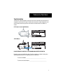
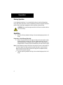
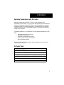
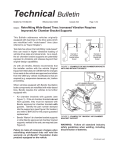
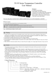
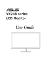
Driver Instructions
Eaton Fuller® Heavy-Duty
Transmissions
TRDR0515 EN-US
June 2014
RT-6610
RT, RTX-1X610 Series
RT, RTX-1X710 Series
FR, FRM, FRO, FRW-1X210 Series
FR-9210
RTO-6610
RTO-1X610 Series
Warnings
Warnings and Cautions
!
WARNING
Read the entire driver instructions before operating this transmission.
Before starting a vehicle, always be seated in the driver’s seat, place the shift
level to neutral, and disengage the clutch.
If engine cranks in any gear other than neutral or without the master clutch
depressed, service your vehicle neutral safety start circuit immediately.
Before working on a vehicle or leaving the cab with the engine running, place
the transmission in neutral and set the parking brakes, and block the wheels.
Do not release the parking brake or attempt to select a gear until the air pressure is at the correct level.
When parking the vehicle or leaving the cab, always place the shift lever in
neutral and set the parking brakes.
TOWING: To avoid damage to the transmission during towing, disconnect the
driveline.
Every effort has been made to ensure the accuracy of all information in this
brochure. However, Eaton makes no expressed or implied warranty or representation based on the enclosed information. Any errors or omissions may
be reported to Technical Services, Eaton, P.O. Box 4013, Kalamazoo, Michigan 49003-4013.
Table of Contents
Introduction
Tag Information ..................................................................................... 1
Nomenclature........................................................................................ 2
Shift Lever Positions
Shift Positions....................................................................................... 3
General Information
General Information ............................................................................... 4
Operation
Driving Operation ................................................................................... 6
Lubrication
Proper Lubrication .............................................................................. 10
Preventive Maintenance
Maintenance Checks............................................................................ 12
Reference Numbers
Tag Information
Transmission model designation and other transmission identification information are
stamped on the transmission tag. To identify the transmission model designation and
serial number, locate the tag on the transmission and then locate the numbers as
shown.
All 10-Speed except 1X210 Models
Eaton Fuller
Transmissions
Model
PTO Code
Serial
RT-11710A
Eaton Corporation
Transmission Div
Kalamazoo, MI 49003
Made
In
1X210 Models
Eaton Fuller
Transmissions
Model
PTO Code
Serial
RTO-14210-C
Eaton Corporation
Transmission Div
Kalamazoo, MI 49003
Made
In
DO NOT REMOVE OR DESTROY THE TRANSMISSION IDENTIFICATION TAG.
Record transmission identification data. Have these reference numbers handy when
ordering replacement parts or requesting service information.
Transmission Model: ______________________________________
Transmission Serial Number: _________________________________
1
Model Designations
Nomenclature
R T X F - 11 7 10 B
Ratio Set
Roadranger
Twin Countershaft
O - Overdrive
X - Direct
Forward Shift
Bar Housing
2
Forward Speeds
Design Level
This (x) 100 = Nominal Torque Capacity
Shift Lever Diagram
Shift Positions
RT 6610 Series / RT, RTX 1X610 Series / RT, RTX 1X710 Series / FR, FRM,
FRO, FRW 1X210 Series / FR 9210 Series
RTO 6610 Series / RTO 1X610 Series
3
General Information
General Information
This Eaton® Fuller® Roadranger transmission model contains ten forward speeds and
two reverse speeds. The gear shift lever mechanically engages and disengages five
forward gears and one reverse gear in the transmission front section. The range lever
on the Roadranger Valve allows the operator to control an air shifted auxiliary section
to provide a LO and HI “range”. The five forward gears selected in LO range are used
again in HI range to provide the 10 progressive forward gear ratios.
Once the highest shift lever position (5th gear) is obtained in LO range, the operator
preselects the range shift lever for HI range. The range shift occurs automatically as the
shift lever is moved from 5th gear position to the 6th gear position.
When downshifting, the operator preselects the range lever for LO range and the range
shift occurs automatically during the shift lever movement to the next gear position.
Transmission Features
Range Shift
The range lever selects LO or HI range. It is used once during an upshift sequence and
once during a downshift sequence.
Preselect
IMPORTANT: Always preselect all range shifts when upshifting or downshifting.
Preselection requires that the range lever is moved to the needed position before
starting the shift.
Preselected range shifts are completed automatically as the lever is moved through
neutral and into the next gear. Preselecting all range shifts prevents damage to the
transmission and provides for smoother shifts.
4
General Information
Optional Equipment
For easier and faster gear engagement while the vehicle is standing still, some Eaton®
Fuller® transmissions may be equipped with either a Countershaft Brake or a Clutch
Brake.
Countershaft Brake (Used with push-type clutches)
The control button is mounted on the shift lever just below the shift knob. To operate,
disengage the clutch, press down the control button, and shift into LO or reverse. This
is an air operated mechanical brake which slows down the transmission gearing by
forcing a piston against the countershaft PTO gear. Never use the Countershaft Brake
when upshifting or downshifting. Use only for initial gear engagement when the vehicle
is standing still.
Clutch Brake (Used with pull-type clutches)
The clutch brake is applied by fully depressing the clutch pedal to the floor board.
When applied the brake slows down and can stop the transmission front box gearing. It
is a disc-type brake incorporated into the clutch and transmission drive gear
assemblies. Never use the Clutch Brake when upshifting or downshifting. Use only for
initial gear engagement when the vehicle is standing still.
5
Operation
Driving Operation
Driving Tips
•
•
•
•
•
•
•
•
•
Always use normal double-clutching procedures when making lever shifts.
Always select an initial starting gear that provides sufficient reduction for the
load and terrain.
Never slam or jerk the shift lever to complete gear engagements.
Never coast with the shift lever in the neutral position.
Never downshift at too high of a road speed.
Never move the range lever with the shift lever in neutral while the vehicle is
moving.
Never make a range shift while moving in reverse.
In most cases, depending on the engine and axle ratios, you can save valuable
fuel by operating the vehicle at less than governed RPM while cruising in top
gear.
If the lever shift is completed before the range shift (transmission in neutral),
the lever must be moved back to neutral for the range to complete (1X210
models only).
Double-Clutching Procedure
When ready to make a shift:
1. Depress pedal to disengage clutch.
2. Move the shift lever to neutral.
3. Release pedal to engage clutch.*
a.
4.
5.
Upshifts—decelerate engine until engine RPM and road speed match.
b. Downshifts—accelerate engine until engine RPM and road speed match.
Quickly depress pedal to disengage clutch and move shift lever to next gear
speed position.
Release pedal to engage clutch.
Note: *By engaging the clutch with the shift lever in the neutral position, the operator
is able to control the mainshaft gear RPM since it is regulated by engine RPM.
This procedure allows the operator to speed up or slow down the mainshaft
gearing to properly match the desired gear speed and the output shaft speed.
6
Operation
Initial Start-Up
WARNING: Before starting a vehicle always be seated in the driver’s seat,
move the shift lever to neutral, and set the parking brakes.
1.
2.
3.
4.
5.
Make sure the shift lever is in neutral and the parking brakes are set.
Turn on the key switch to start the engine.
Allow the vehicle air pressure to build to the correct level. Refer to your
"Operator and Service Manual" supplied with the truck.
Apply the service brakes.
Make sure the range lever is down in the LO range position.
Range Lever MUST be
in the LO Range position
for LO Range.
6.
7.
8.
9.
Depress the clutch pedal to the floor.
Move the shift lever to desired initial gear.
Release the parking brakes on the vehicle.
Slowly release the clutch pedal and apply accelerator.
7
Operation
Driving Operation
In the following instructions, it is assumed that the driver is familiar with operating
heavy-duty trucks and tractors, and can coordinate the shift lever movement and clutch
pedal to make smooth gear engagements while upshifting or downshifting.
CAUTION: Never move the range lever with the shift lever in neutral while the
vehicle is moving.
Upshifting
1.
Move the shift lever, double-clutching, to the next desired gear position in LO
range.
Range shift—LO to HI Range (5th to 6th)…
2. When in last gear position for LO range and ready for the next upshift, pull up
the Range Selector and move the shift lever, double-clutching, to the next
higher speed position according to your shift pattern. As the shift lever passes
through neutral, the transmission will automatically shift from LO to HI range.
Note: If after attempting a range shift to HI the transmission remains in neutral with the
shift lever in gear, the range synchronizer protection device may be activated.
Move the shift lever into neutral to allow the range shift to complete and then,
move the shift lever back into gear.
3.
8
Continue upshifting, double-clutching, to the next desired gear position in HI
range.
Operation
Downshifting
1.
Move the shift lever, double-clutching, to the next desired gear position in HI
range.
Range shift from HI Range to LO Range (6th to 5th)…
2. While in 6th and ready for the next downshift, preselect LO range, push the
Range Selector down.
3. Move the shift lever, double-clutching, to the next desired gear position in LO
range. As the shift lever passes through neutral, the transmission
automatically shifts from HI range to LO range.
4. Continue downshifting, double-clutching, to the next desired gear position in
LO range.
9
Lubrication
Proper Lubrication
The Key to Long Transmission Life
Proper lubrication procedures are the key to a good all-around maintenance program.
Eaton® Fuller® Transmissions are designed so that the internal parts operate in an oil
circulating bath created by the motion of the gears and shafts.
All parts will be properly lubricated if these procedures are closely followed:
• Maintain oil level. Inspect regularly.
• Follow maintenance interval chart.
• Use the correct grade and type of oil.
• Buy from a reputable dealer.
Maintain Proper Oil Level
Make sure oil is level with the filler opening. Being able to reach oil with your finger
does not mean oil is at proper level. (One inch of oil level is about one gallon of oil.)
Hole
Proper Oil Level
Hole
Improper Oil Level
For additional lubrication information, see TCMT-0021.
If your vehicle has a transmission oil filter, you must change the filter when fluid or
lubricant is changed.
Additive and friction modifiers must not be introduced. Never mix engine oils and
gear oils in the same transmission.
Do not use EP gear oil or multi-purpose gear oil.
The use of lubricants not meeting these requirements will affect warranty coverage.
For a list of Eaton Approved Synthetic Lubricants see TCMT-0020 or call 1-800-826HELP (4357).
10
Lubrication
Operating Temperatures with Oil Coolers
Operating at temperatures above 250° F (120°C) causes loaded gear tooth
temperatures to exceed 350°F (177°C) which will ultimately destroy the heat treatment
of the gears. Temperatures above 250°F (120°C) should be regarded as a warning of
inadequate cooling. If the elevated temperature is associated with unusual operating
conditions that will reoccur, a cooler should be added, or the capacity of the existing
cooling system increased.
The following conditions in any combination can cause operating temperatures of over
250°F:
• Operating consistently at slow speed.
• High ambient temperatures.
• Restricted air flow around transmission.
• Exhaust system too close to transmission.
• High horsepower operation.
External oil coolers are available to reduce operating temperatures when the above
conditions are encountered.
Oil Cooler Chart
Transmission Oil Coolers are:
Recommended
• With engines of 350 H.P. and above.
Required
• With engines 399 H.P. and above and GCW's over 90,000 lbs.
• With engines 399 H.P. and above and 1400 lbs. ft. or greater torque.
• With engines 450 H.P. and above.
11
Preventative Maintenance
Maintenance Checks
The following maintenance items are necessary to prevent costly transmission failures
which may not be covered by warranty.
Grease Fitting On
Each Side To
Lubricate Clutch
Pedal Shaft
Air Shift Module
Shift Tower
Output
Seal
Oil Fill Plug
Clutch Inspection
Cover
Oil Drain
Plug
Transmission Oil -
12
•
Check transmission daily for oil leaks. Repair promptly to prevent oil loss
and subsequent transmission failure.
•
Check transmission oil level at every engine oil change interval. Add
transmission oil as necessary.
•
Drain and replace transmission oil as recommended by the schedule in
this book.
Preventative Maintenance
Air System •
Drain moisture from vehicle air system daily.
•
Listen for air leaks daily, repair promptly.
•
If the vehicle is equipped with an air dryer, confirm that the air dryer
system is working properly. Repair as necessary.
•
Service the vehicle air compressor as required to prevent oil from
entering the vehicle air system.
Master Clutch System •
Lubricate clutch release pedal shaft bushings at every chassis lubrication
interval. There should be one grease fitting on each side of the
transmission clutch housing.
•
Have the clutch checked and adjusted if any of the following occurs:
•
Clutch does not disengage completely
•
Clutch brake does not function
•
Clutch pedal free-play is less than 1/2”
•
When replacing the clutch, use a high quality spring damped replacement
unit.
Drivetrain •
Inspect the driveshaft for loose or worn U-joints weekly. Repair promptly
to prevent excessive driveline vibration.
•
Have the driveline checked by a maintenance facility if unusual noise or
vibration is detected.
Overall Inspection •
Inspect the transmission at the chassis lubrication interval for loose or
missing capscrews and fasteners. Pay particular attention to the
capscrews that attach the transmission to the engine.
13
Copyright Eaton, 2014.
Eaton hereby grant their customers,
vendors, or distributors permission
to freely copy, reproduce and/or
distribute this document in printed
format. It may be copied only in
its entirety without any changes or
modifications. THIS INFORMATION
IS NOT INTENDED FOR SALE OR
RESALE, AND THIS NOTICE MUST
REMAIN ON ALL COPIES.
Note: Features and specifications
listed in this document are subject to
change without notice and represent
the maximum capabilities of the
software and products with all options
installed. Although every attempt has
been made to ensure the accuracy of
information contained within, Eaton
makes no representation about the
completeness, correctness or accuracy
and assumes no responsibility for
any errors or omissions. Features and
functionality may vary depending on
selected options.
For spec’ing or service assistance,
call 1-800-826-HELP (4357) or visit
www.eaton.com/roadranger.
In Mexico, call 001-800-826-4357.
Roadranger: Eaton and trusted partners
providing the best products and services in the
industry, ensuring more time on the road.
Eaton
Vehicle Group
P.O. Box 4013
Kalamazoo, MI 49003 USA
800-826-HELP (4357)
www.eaton.com/roadranger
Printed in USA