1
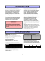
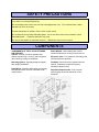
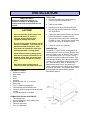
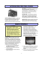
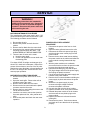
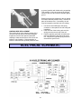
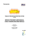
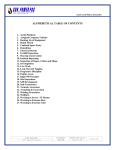
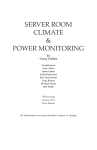
OWNER AND SERVICE MANUAL CAUTION! SHARP EDGES WEAR GLOVES FOR INSTALLATION SMOKEMASTER® MODEL X-11Q SELF-CONTAINED ELECTRONIC AIR CLEANER Mail: Air Quality Engineering 7140 Northland Drive N. Brooklyn Park, MN 55428 USA Phone: Fax: e-mail: web: 1.800.328.0787 763.531.9823 763.531.9900 [email protected] www.air-quality-eng.com 2007 Air Quality Engineering, Inc. copyrights this manual with all rights reserved. Under the copyright laws, this manual may not be reproduced in any form, in whole or in part, without the prior written consent of Air Quality Engineering, Inc. All statements, technical information and recommendations in this manual or related documents are believed reliable, but the accuracy and completeness thereof are not guaranteed or warranted, and they are not intended to be, nor should they be understood to be representation or warranties concerning the products described. Specifications are subject to change without notice. TABLE OF CONTENTS PRINCIPLES OF OPERATION 2 INTRODUCTION 3 SPECIFICATIONS 3 SAFETY PRECAUTIONS 4 COMPONENTS 4 INSTALLATION 5 ELECTRICAL INSTALLATION 6 CHECKOUT 7 OPERATING INSTRUCTIONS 8 MAINTENANCE 8 SERVICE 9 ELECTRICAL SCHEMATIC 10 ELECTRICAL TROUBLESHOOTING 11 PARTS LIST 12 WARRANTY 13 PRINCIPLES OF OPERATION HOW YOUR ELECTRONIC AIR CLEANER WORKS A process called “Electrostatic Precipitation” traps airborne contaminants. The fan draws particulate laden air successively through the prefilter, the cell ionizing section and the cell collector section. The ionizing section imparts an electrical charge to the individual particles that are then drawn by electrostatic forces to the oppositely charged collector plates. Cleaned air is then discharged back into the room. FIGURE 1 The electronic cells must be washed periodically to maintain efficient performance. 2 INTRODUCTION Recommended quantities of clean outdoor ventilation air for various applications are described in Table 2 of the ASHRAE Standard 62-89, “Ventilation for Acceptable Indoor Air Quality.” ASHRAE (American Society of Heating, Refrigerating and Air Conditioning Engineers, Inc., Telephone #404-636-8400) notes that these recommended outdoor air quantities may be reduced by the use of clean, recirculated air if the IAQ Procedure 6.2 is used. Appendix E of ASHRAE 62-89 includes recommendations for the use of clean, recirculated air. However, in most cases, adequate control of carbon dioxide generally requires a minimum clean outdoor air quantity of no less than 15 cubic feet of air per minute per person. Your Smokemaster® X-11Q Electronic Air Cleaner is an advanced self-contained electronic air cleaner. The Model X-11Q is an efficient indoor pollution fighter while reducing costly energy consumption. It is designed to be installed in the space of a 2 x 4-drop ceiling panel. Typical installations include conference rooms, lounges, offices, lunchrooms, etc. Because it provides its own air circulation, the X-11Q may be used in almost any application requiring the removal of airborne particulate contamination from an enclosed space. WARNING! The X-11Q Electronic Air Cleaner is not explosion-proof. It must not be installed where there is danger of vapor, gas or dust explosion. Additional ventilation may be required for toxic contaminants. In any event, the air cleaner must be used only in areas that are ventilated for human occupancy in order to dissipate any incidental generation of ozone. SPECIFICATIONS DIMENSIONS: 48” x 24” x 13 5/8”; [1218 mm x 609 mm x 436 mm] WEIGHT: 101 Lbs. [46 Kg] shipping; 83 Lbs. [38 Kg] installed, including electronic cells. Each cell weighs 9 ½ Lbs. [4.3 Kg]. Efficiencies when tested at 1000 cfm. Size Range Efficiency 0.7-1.0 96.0 2.2-3.0 98.2 4.0-5.5 99.1 7.0-10.0 99.8 EFFICIENCY: Up to 99.8% efficiency is delivered as measured according to the American Society of Heating, Refrigerating and Air Conditioning Engineers (ASHRAE) Standard 52.2. ELECTRICAL RATINGS: Voltage and Frequency: 120V, 60 Hz; 220/240V, 50 Hz CURRENT AND POWER CONSUMPTION: FAN SPEED High Med. Low 120V, 60 HZ WATTS AMPS 185 1.8 140 1.5 120 1.3 220/240V, 50 HZ WATTS AMPS 185 .9 155 .7 605 .6 MODEL X-11 CFM Noise Level AMBIENT TEMPERATURE RATING: Shipping and Storage: -40°F to +150°F; (-40°C to +66°C). 3 Low 350 51 dB(A) Medium 725 59 dB(A) High 1100 69 dB(A) SAFETY PRECAUTIONS Do not disassemble or modify. - Fire and/or electrical shock may occur as a result. For repair, contact your dealer or Air Quality Engineering. Do not damage power cord or use unit with a damaged power cord. Fire, electrical shock, and/or damage may occur as a result. Use the appropriate AC voltage, 120V or 220V, power source. Do not allow the unit to intake flammable gases. Do not use where there is accumulation of such flammable gases. - Explosion and/or fire may occur. Do not use with prefilter or main filter removed. - Malfunction may occur as a result. COMPONENTS Power Module - Removable power module contains all electronic circuitry for easy service. COMPONENTS OF THE X-11Q ELECTRONIC AIR CLEANER Cabinet - A sturdy corrosion resistant steel cabinet requires only a 13 9/16” [344 mm] space above the drop ceiling for installation. Electronic Cells - Two electronic cells charge and collect the airborne particles. Fan Motor - Motor driven fan operates at three speeds. Elastomeric suspension system eliminates vibration noise. Mounting System - Specially designed support bars simplify installation. Intake Grille - Attractive intake grille conveniently swings down with a one-inch removable metal mesh prefilter. Adjustable Exhaust Grille - Four louvered exhaust grilles direct the cleaned air in four directions. 4 INSTALLATION UNPACKING 1. Remove the intake grille (center grille) by turning the quarter turn fasteners. IMPORTANT! Read these instructions carefully. A hazardous condition or damage to the product could result if instructions are not followed. 2. Take out the prefilter. 3. Remove the electronic cells by turning the two retaining turnstile latches, then raise the cell off the hooks. CAUTION! 1. Do not connect the power source until after the electronic air cleaner is mounted. Electrical shock and equipment damage may result. 4. Unplug the power module from the air cleaner before attempting to complete removal. Unscrew and remove the power module (see FIGURE 3). Hint: Tilt the power module away from the air cleaner to facilitate removal. 2. Be sure to turn off the air cleaner prior to service or installation. The motor has an automatic thermal overload so it will stop when it is overheated. It will automatically start after a cooling period. 5. Lift the air cleaner out of the box. PREPARATION The Model X-11Q Air Cleaner is designed to be installed within a T-bar drop ceiling. Remove tiles from the ceiling to open an area 23” [583.76 mm] x 47” [1192.89 mm] (one 2’ [.61 m] x 4’ [1.22 m] ceiling tile) to accommodate the air cleaner. The area between the drop ceiling and the true ceiling must be free of obstructions such as pipes, ducts, etc. There must be at least 14” [355.33 mm] between the bottom of the T-bar and the true ceiling. Make sure the air cleaner will be oriented for good air circulation. The exhaust grilles can be disassembled and reassembled to provide alternate air patterns. 3. Avoid electrical shock by being careful when the air cleaner is turned on for an electrical check. Also, be careful when working near the air cleaner’s moving parts. 4. Wear gloves when installing the air cleaner to protect your hands from cuts. EQUIPMENT NEEDED • Philips screwdriver • Wire cutters • Pliers • Knife • Hacksaw • Electric drill with 1/8” [3.17 mm] bit • Wire pliers • Four ¼” [6.36 mm] turnbuckles • Twelve-gauge galvanized steel wire • Twelve or fourteen-gauge electrical wire and conduit • Junction box fittings, as needed. ITEMS SUPPLIED AS LOOSE PARTS • Two support bars • Six #8, self-tapping, sheet metal screws • Four flat washers • Two wire connectors • Four vinyl extrusions FIGURE 3 5 4. Hook the turnbuckles to the support bars and then secure the support wires to the eyes of the turnbuckles (see Fig. 5). Twist the wire at least four times. WARNING! The following instructions are intended for qualified service personnel only. Dangerous line voltage circuits are exposed during this procedure. Disconnect power at the fuse before servicing unit. 5. Adjust the turnbuckles until the support bars are securely suspended by the support wires. Do not over tighten the turnbuckles to avoid lifting or buckling the T-bar framework. MOUNTING 6. Lift the air cleaner body into the opening and let the body drop into the J-shaped portion of the support bars. 1. Attach four 12-gauge, galvanized steel support wires to the true ceiling at the location shown in FIGURE 3. Twist each wire at least four times to provide safe support for the air cleaner. The free end of each wire should extend six inches or more below the bottom of the T-bars. 7. Fasten the air cleaner body to the support bars using four #8, self-tapping screws and flat washers. The screws are installed through slots in the ends of the air cleaner into support bars. Adjust the location of the air cleaner relative to the support bars via slots prior to tightening of the screws. 2. At the end of each opening, set a support bar across the T-bars. The “J” shaped portion of the support bars should be oriented so the hook side of the “J” is toward the opening (not toward the adjacent T-bars). See FIGURE 3. 8. Install U-shaped, vinyl extrusions around the perimeter of the air cleaner. Vinyl extrusions slip over the lip of the T-bar and trim out the air cleaner in the event of uneven gaps. 3. Using an electric drill with a 1/8” [3.17 mm] drill bit, drill through the holes in the stepped portion of the support bars and through the T-bars. Attach the support bars to the T-bars with four #8, sheet metal screws provided. ELECTRICAL INSTALLATION 3. CAUTION: Turn off the building circuit at the fuse or circuit breaker before proceeding. CAUTION! Only persons qualified to install electrical wiring should attempt this procedure. All wiring must comply with applicable codes and ordinances. 4. Connect the black and white wires from the pigtails in the air cleaner junction box to the corresponding colors in the supply circuit (FIGURE 4). 1. Locate an unswitched 120V, 60 Hz or 220V, 50 Hz power circuit with a junction box near the air cleaner location. 2. Check the circuit breaker or fuse for that circuit and determine whether it is rated 15 Amps or 20 Amps (as marked on the device). The required copper wire size will be: AWG #14 for 15 ampere circuits AWG #12 for 20 ampere circuits FIGURE 4 6 white wire of the building. The air cleaner frame must be electrically connected to the frame of the building or the electrical conduit system. Input electrical power should be run through flexible conduit as recommended by the National Electrical Code or your local authority. EXHAUST GRILLE ORIENTATION AND INSTALLATION Each of the four louvered exhaust grilles can be oriented individually to provide an optimum airflow pattern. Simply unscrew the louvered grilles from the grille bars, rotate to any of three directions* and reattach grilles to bars. Screw exhaust grille assemblies to air cleaner. (See FIGURE 5) FIGURE 5 5. Connect a green wire from the grounding terminal in the air cleaner junction box to the grounded conduit of the building wiring system. If the building does not have conduit, it will have a green or bare grounding conductor for connection to the air cleaner green wire. DO NOT connect the grounding wire from the air cleaner to the *Orienting a louvered grille to blow air back toward the intake grille (fourth direction) is not recommended since good circulation of cleaned air in the room is defeated. CHECKOUT 5. Turn the electrical power back on. 1. Make sure the X-11Q is securely fastened to the true ceiling. 6. Make sure the fan runs on all three-speed 2. Replace the power module and reconnect settings. The system light should be on the electronic plugs. when the fan is running. 3. Check to make sure the electronic cells are 7. Press the test button. An audible snap oriented for correct airflow--arrows on side indicates the collection section of the cell is of cell should point up. The contact board functioning. on the cell should align with the contact 8. Opening the intake grille stops the fan and board on the power module. turns out the system light. 4. Make sure the intake grille opens easily and 9. Clean up surfaces of the air cleaner and the the electronic cells and the prefilter are installation area. secure in the unit. NOTE: If the X-11Q does not appear to work right, refer to the Electrical Troubleshooting section. 7 OPERATING INSTRUCTIONS FAN SWITCH - Your electronic air cleaner has an Off-Low-Med-Hi switch. The electronic collection system and built-in fan are designed to run simultaneously. Turn off the air cleaner before opening the access door to remove the electronic cells for cleaning. SYSTEM LIGHT - Your electronic air cleaner is equipped to tell you simply and quickly that it is working properly. The amber system light tells you at a glance the status of the power supply. The system light should be on when the unit is on. FIGURE 6 SAFETY INTERLOCK SYSTEM - In order for all air cleaner functions to receive operating power, the grille must be securely in position. This actuates the safety interlock switch. The air cleaner will not function without the grille in place. TEST BUTTON - Pushing the white button labeled “push to test” generates a snapping noise that indicates proper function of the collector system. MAINTENANCE 4. Thoroughly rinse cells with very hot water. Make certain no residue remains. 5. Inspect collector plates for cleanliness. Repeat wash procedure, if necessary. 6. Using AQE Cell Coat p/n 45023 will allow better release of contaminant when washing. 7. Check the electronic cells for broken wires and bent collector plates. The cells may be installed in the air cleaner and energized. The indicator light may remain off during the normal two hour drying time. However, if annoying arcing occurs during this period, the cell may be removed to dry. CAUTION! 1. BE EXTREMELY CAREFUL WHEN WORKING WITH THE X-11Q CELLS AND FILTERS. The edges of the cells and filter, and the collection plates and ionizing wires of the cell may be sharp. 2. When cleaning the cells and filters, be sure to wear appropriate protective gear, especially goggles and gloves. Skin contact with alkaline detergent solution should be avoided. See warning label on detergent. WASHING THE ELECTRONIC CELLS AND PREFILTER - To maintain peak efficiency, the electronic cells and prefilter in your electronic air cleaner must be washed regularly with Air Quality Engineering’s Detergent Concentrate. Washing is necessary to remove dirt particles collected from the air. The intake grille may be removed from the machine for periodic washing. A wash kit is available from Air Quality Engineering. 1. Fill wash tub with cell cleaning detergent p/n 45008 and hot water per detergent manufacturer’s instructions. 2. Immerse cells in the cleaner solution and remove immediately. 3. Set cells aside for five minutes to allow the cleaner to penetrate. FIGURE 7 8. CELL CLEANER IS REUSABLE. SAVE FOR REPEATED USE. Replace cleaning solution when cells are no longer being effectively cleaned. 9. Remove lint from prefilter with vacuum cleaner or wash with mild detergent solution. 8 SERVICE WARNING! The following instructions are intended for qualified service personnel only. Dangerous line voltage circuits are exposed during this procedure. Disconnect the power at the fuse before servicing the unit. MOTOR MAINTENANCE PROCEDURE The manufacturer of the motor used in the X-11Q recommends oiling the motor at least once a year. The following procedure can be followed: FIGURE 8 1. De-energize the unit. 2. Remove the prefilter and cells from the cabinet. 3. Remove the fan blade from the motor shaft. 4. Unscrew the four screws holding the motor mounting plate and lower the motor. THE WIRING NEED NOT BE DISCONNECTED. 5. There are two oil holes on the motor: a. Near the motor shaft. b. On the end opposite the motor shaft near the bearing plate. POWER SUPPLY REPLACEMENT PROCEDURE 1. Disconnect the power at the fuse or circuit breaker. 2. Open the intake grille and remove the cells. 3. Disconnect the three-wire power input plug and the six-wire motor control plug from the power module. 4. Remove the two sheet metal screws holding the power module to the cabinet and allow the power module to swing forward and drop down. 5. With the power module on a workbench, remove the back cover from the power module by removing eight sheet metal screws. 6. Disconnect the dark gray (P4) and the pink (P3) high voltage wires from the power supply and unplug the plastic connector. 7. Cut the wire ties holding the power supply wire harness to the power module. 8. Remove the four nuts and washers holding the power supply in place and remove the power supply. 9. Mount the new power supply in place, reconnect the high voltage wires and reconnect the plastic connector. 10. Use wire ties and re-tie the wires in place. 11. Replace the back cover of the power module. 12. Reinstall the power module in the air cleaner and reconnect the two plastic plugs to the power module. 13. Replace the electronic cells and close the intake grille. 14. Reconnect the power. Push the test button and check to be sure that the unit is operating properly. Five drops of SAE 20 weight non detergent oil or electric oil in each hole is adequate. Wipe off the excess oil that misses or runs out of the oil holes. Replace the motor fan blade, cells and prefilters in the unit. Re-energize the unit and check it out to ensure proper operation. MOTOR REPLACEMENT PROCEDURE 1. Disconnect the power at the fuse or circuit breaker. 2. Open the intake grille. Remove the cells to provide access to the motor. 3. Remove the fan blade from the motor. 4. Disconnect the fan motor leads at the plastic connector near the fan motor. 5. Remove the four nuts holding the motor to the unit to remove the motor. 6. Install the new motor, connect the electrical lines and replace the fan, cells, prefilter and grille. 7. Connect the power and check the new motor operation. 9 to ground, possibly with visible arcing or sparking. This condition, or any other short in the ionizing section of the cell, will cause the indicator light to go out. Broken wires must be replaced for the air cleaner to function effectively without arcing. Remove all parts of the broken wire. If necessary, the cell may be temporarily used with one wire missing. 1. Use care to avoid damage to the spring connector or other parts of the cell during the installation. 2. Hook one end of the ionizing wire over the spring connector at one end of the cell. 3. Hold the opposite eyelet with a needle nose pliers and stretch the wire the length of the cell. Depress the opposite spring connector and hook the eyelet over it. FIGURE 9 – INSTALL NEW IONIZING WIRES IONIZING WIRE REPLACEMENT The ionizing wires in the charging section of the electronic cell may break or become damaged. Inspect the cell from the upstream side after washing to make sure that none of the wires are broken or out of position. During operation, a broken or deformed wire generally causes a short ELECTRICAL SCHEMATIC 10 ELECTRICAL TROUBLESHOOTING WARNING! The following instructions are intended for qualified service personnel only. Dangerous line voltage circuits are exposed during this procedure. Disconnect the power before servicing the unit. Check circuit fuse or breaker. Correct if fuse is blown or breaker is tripped. Be sure the electronic cells are in place, the intake grille is closed and the unit is turned on. ARCING From time to time, you may hear a snapping noise coming from the electronic air cleaner. This arcing occurs when the air cleaner collects an unusually large particle or when the cells are wet, extra-ordinarily dirty or damaged. If an unusual amount of arcing persists, check first to determine if the electronic cells need washing. Look also for any sign of bent collector plates or broken ionizer wires. If arcing still occurs when the cell is clean and dry, consult your Air Quality Engineering, Inc., representative or dealer for repair. PROBLEM 1 PROBLEM 2 PROBLEM 3 FAN OFF LAMP OFF FAN ON LAMP OFF FAN OFF LAMP ON 1. Make sure the supply cord is plugged into a standard receptacle. 1. If the fan is on and the light is out, the problem is with the electronic cell or high voltage power supply. 1. Check the motor on all three speeds. Be certain that the control buttons are pushed in all the way. 2. To determine which component is faulty… - Remove the electronic cell, and operate the X-11Q. If the light does not come on, then the high voltage power supply will have to be replaced. 2. If the light is on and the fan is off. The motor will have to be replaced. 2. Make sure there is voltage to the receptacle by using any other electric device. 3. Make sure the top access cover is properly in place in order to actuate the interlock switch. 3. If the indicator light does come one, the problem is with the electronic cell. Check the cell for: a. Bent collector plates. Straighten and space the plates using a needle nose pliers. b. Check for missing ionizer wires. Replace the missing wires. c. Check for dirty buildup on the collector plates and the insulators. Wash the cell thoroughly. 11 PARTS LIST NO 1 2 3 4 5 6 7 8 9 10 11 DESCRIPTION Grille Assembly Louver Assembly Power Module Assembly/60 Hz Power Module Assembly/50 Hz System Light Speed Control Switch Interlock Switch Louver Hanger Bracket Push Button Fastener before Dec 06 Quarter Turn Fastener after Dec 06 Fan Blade Electronic Cell PART # 05112 05113 05116 05367 10097 10110 10106 20668 20675 07234 07279 37022 38001 12 13 14 Motor Replacement Kit/60 Hz Motor Replacement Kit/50 Hz Prefilter Heavy Duty Prefilter Contact Board Assembly PARTS NOT ILLUSTRATED Capacitor Power Supply/60 Hz Power Supply/50 Hz Ionizing Wires Wash Kit (Includes Wash Container & 4 Gallons Detergent & Cell Coat) Detergent Concentrate Cell Coat 12 05299 05360 41021 41107 05110 PART # 40117 07070 07088 38004 55555 45008 45023 CERTIFICATE OF WARRANTY ONE - YEAR LIMITED WARRANTY Air Quality Engineering, Inc., warrants to the original purchaser, subject to the conditions below, that should the product covered by this warranty (“product”) fail to perform by reason of improper workmanship or material, Air Quality Engineering, Inc., (AQE) will, during the period of one (1) year from the date of original purchase either (i) replace the Product or (ii) provide all necessary parts to repair the Product, without charge. The decision to replace the Product or the necessary parts shall rest solely with AQE. This one-year limited warranty does not apply to main filter elements. Air Quality Engineering, Inc., will replace without charge the main filter elements during the period of thirty (30) days from the date of original purchase if the main filter elements fail to perform by reason of improper workmanship or material. This warranty is valid only under the following conditions: CONDITIONS 1. AUTHORIZATION: Purchaser will contact Air Quality Engineering, Inc., 800-328-0787, for authorization, returned goods authorization number (RGA) and shipping address. AQE will direct purchaser to either return the necessary parts or the Product at AQE’s option. 2. PROPER DELIVERY: The shipping, freight prepaid, or delivery of the parts or the Product to Air Quality Engineering, Inc., in either its original carton or in a carton assuring similar protection of the Product with returned goods number (RGA) clearly displayed on the outside of the carton. 3. UNAUTHORIZED REPAIR: A showing by the original purchaser that the Product has not been altered, repaired or serviced by anyone other than an authorized service technician using genuine AQE parts. 4. UNAUTHORIZED PARTS: A showing by the original purchaser that the Product has had only genuine Air Quality Engineering, Inc., parts and filters used in its operation and maintenance. 5. SERIAL NUMBER INTACT: A showing by the original purchaser that the Serial Number has not been altered or removed. 6. MISUSE: A showing by the original purchaser that the Product has not been involved in an accident, freight damaged, misused, abused or operated contrary to the instructions contained in the Owner’s Manual. Air Quality Engineering, Inc.’s, sole responsibility shall be to repair or replace the Product within the terms stated above. AQE shall not be liable for any consequential damages resulting from and breach of warranty, express or implied, applicable to the Product. Some states do not allow the exclusion or limitation of consequential damages so this limitation may not apply to you. THIS WARRANTY IS IN LIEU OF ALL OTHER WARRANTIES, EXPRESS OR IMPLIED, INCLUDING THE WARRANTIES OF MERCHANTIBILITY AND FITNESS FOR A PARTICULAR PURPOSE. Some states do not allow limitations on how long an implied warranty lasts so the above limitation may not apply to you. This warranty gives you specific legal rights and you may also have other rights that vary from state to state. AIR QUALITY ENGINEERING, INC. 7140 NORTHLAND DRIVE NORTH MINNEAPOLIS, MINNESOTA 55428-1520 TOLL FREE: 1-800-328-0787 TELEPHONE: (763) 531-9823 FAX: (763) 531-9900 MANUFACTURER & WORLDWIDE DISTRIBUTOR OF SMOKEMASTER® AIR CLEANING SYSTEMS PN 51414 Rev. C Printed in the USA