1
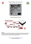
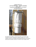
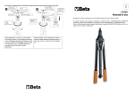
Tinius Olsen Ltd.
6 Perrywood Business Park
Honeycrock Lane, Salfords
Redhill, Surrey, RH1 5DZ, UK
Tel: +44 (0) 1737 765001
Fax: +44 (0) 1737 764768
[email protected]
www.TiniusOlsen.com
500L Laser Extensometer
Operating Instructions
Rev B – 1 March 2004
Tinius Olsen Ltd, Registered in England Number 998521
500L Laser Extensometer
Operating Instructions
Contents
Section
1
2
3
4
5
6
7
8
9
10
11
12
13
14
15
16
17
18
19
20
21
22
23
24
25
26
27
28
29
30
31
32
Title
Caution
Introduction
Installation
Initial Setup
Recorder Range
Extension Hold
Hold Off
Hold On
Threshold Level
Ten/Comp
Tension Mode
Compression Mode
Rapid Menu Selection
Benchmark Errors
No Benchmarks
One Benchmark
Many Benchmarks
Zero Button
X10 Button
Checking Operation
Gauge Length
Routine Testing
RS232 Interface
RS232 Cable Connection
Example Program
RS232 Transmission Specification
RS232 Read Commands
RS232 Write Commands
RS232 Command Error List
Benchmark Punch
Re-Loading Benchmark Punch
Laser Extensometer Specification
Page
1
1
2
3
4
4
4
4
4
5
5
5
5
5
6
6
6
7
7
8
8
9
10
10
10
11
12
12
13
14
14
16
500L Laser Extensometer
Operating Instructions
1 Caution
1.1
This product utilises a class II (He Ne) laser and the following
should be adhered to when possible.
1.2
Before powering the unit on, make sure that the unit aperture (at
the left hand side) is directed away from the naked eye and
towards an area which would curtail the laser beam (i.e. wall)
1.3
Avoid looking directly into the laser aperture when the unit is
operative. (Always use an object to allow the (laser beam to
strike if viewing is required).
1.4
Avoid allowing the laser beam to strike a highly polished surface.
(i.e. mirror, polished testpieces)
1.5
1.6
Avoid allowing any person to walk through the laser beam arc if
the unit cannot be arranged as above
If the instrument fails and the scanning mirrors stop, immediately
turn the instrument off.
1.7
Never remove any of the covers of the instrument without
contacting Tinius Olsen or with the relevant service manual.
1.8
The diagram below is a laser radiation warning sign and is
placed at the aperture of the laser extensometer.
Laser Radiation Warning Sign
2 Introduction
2.1
This manual is to help the user to understand the operation of
the electronic control panel of the 500L Laser Extensometer.
2.2
This extensometer has been designed to cover a wide range of
materials being tested in Tension or Compression from 10% to
3000% elongation without contact with the testpiece, using a
unique method developed by Tinius Olsen utilising a low
powered helium neon laser. This instrument incorporates
precision optical components and a very powerful 16 bit micro
processor.
Although the instrument internally is extremely sophisticated,
every effort has been made to make the instrument as simple to
use as possible with the aid of the liquid crystal graphics display.
2.3
There may be many aspects of materials testing not covered in
this operating manual.
Page 1
500L Laser Extensometer
Operating Instructions
2.4
2.5
3 Installation
3.1
Regarding the installation of the 500L laser extensometer on
tensile testing machines other than Tinius Olsen, it will be
necessary for the user to contact Tinius Olsen to obtain specific
dimensions regarding mounting which are not covered in this
manual.
For ease of use, this manual has assumed that the instrument is
to be used with the H10KM Universal Testing Machine and a PC
Compatible computer fitted with two RS232 serial ports.
The extensometer is supplied with the following items. Please
ensure that these items are included before installation.
1.
2.
3.
4.
5.
6.
7.
8.
9.
10.
11.
12.
3.2
Extensometer mounting bar
Extended bottom nose-piece
Tommy Bar
/4" BSF 11/4" hex-head screw
/4" hex key
11/2" x 3/8" mounting washer
4 x 4BA grub screw and hex key
Mains power lead
BNC to BNC recorder cable
BNC to BNC T-piece
RS232 Interface cable
Reflective tape marking punch (if ordered at the time of
purchase)
1
1
Remove all packing from the extensometer taking care that the
controls/display of the instrument are not damaged (before
removing aperture protection, make sure that all surface dust is
removed).
3.3
Before commencing extensometer installation, ensure that the
tensile testing machine is on a horizontal bench with the rear of
the instrument facing the wall or an isolated area. (This is to
ensure that the laser beam from the extensometer does not
come in direct contact with the naked eye).
3.4
Place the extensometer on the bench with the display panel
upwards. Take the extensometer mounting bar 1/4" BSF screw
and 11/2" x 3/8" mounting washer and assemble as shown in fig.1
Figure 1
Page 2
500L Laser Extensometer
Operating Instructions
4 Initial Setup
3.5
Take this assembly to the machine, and with the use of the
extended nosepiece and tommy bar, mount the extensometer
onto the tensile testing machine. Do not fully tighten at this
point.
3.6
Ensure that the laser beam aperture is pointing towards the
nosepiece of the machine. Connect the plug to the mains lead
ensuring that the plug is correctly earthed. Depending on your
mains supply select either the 110 V or 240 V supply on the rear
panel of the machine. (This is achieved with the use of a pen
inserted into the small hole in the centre of the switch, simply
push left or right to select the required voltage).
3.7
Power the instrument on (the laser "on" indicator at this point will
illuminate and a faint red line will be seen striking the crosshead
and/or nosepiece of the tensile testing. machine. The normal
arrangement for the extensometer is to have the mounting bar
approximately 45° to the right of the machine’s front panel.
Rotate the extensometer until the laser scanning beam strikes
the centre line of both nosepieces (ie. load cell nosepiece and
bottom crosshead nosepiece). At this point, it will be necessary
to tighten both the extended nosepiece and laser mounting
screw.
4.1
If the extensometer is still powered on it will be necessary to
turn the instrument off, wait for a few seconds and power back
on again.
4.2
The graphics display on the extensometer will say "please wait,
scanner not at speed". This will automatically change once the
instrument has stabilised to its main display with the heading
HOUNSFIELD and immediately underneath, "error, no bench
marks". Also displayed will be various parameters which will be
required to be set. The main elongation display (contained
within the box) will be blank at this time.
4.3
The user will be required to mark a testpiece with reflective tape
(the tape width should be approximately 1 to 1.5mm placed onto
the sample approximately 25mm apart) and place this marked
testpiece within the grips taking care that the centre line of the
testpiece is aligned with the centre line of the grips. (This is
important with very high extendable materials, while this
material is tested, its cross section will reduce and if this
alignment is not correct, the laser scanning beam will fall outside
the benchmarks causing the test measurement to malfunction).
4.4
The extensometer display should now change from showing the
error "no bench marks"
to an analogue display
and an arbitrary
extension reading. It is
at this point that the
user must set the
recorder range, hold,
and ten/comp mode.
Figure 2 shows the
various parameters to
be set
Figure 2
Page 3
500L Laser Extensometer
Operating Instructions
5 Recorder Range
5.1
To obtain the menus, press the SELECT key whilst holding
down the ENTER key. This will now change the display to the
recorder range menu (if all the recorder percentage indicators
are of normal print, then the recorder ranges have not been
correctly set up). It will be necessary to select a recorder range
even though the recorder output is not used. To set, simply
press the SELECT key, the display will now indicate the
selected recorder range in reverse video. However, if the
instrument is to be used with an analogue recorder and the
required recorder range has not been selected, simply
continue pressing the SELECT key until the correct recorder
range has be obtained indicated by the reverse video. Each
recorder range has a full scale output of +1 volt
(1000,500,200,100,50% on Display x1 and 100,50,20,10,5% on
Display x10)
6 Extension Hold
6.1
The extension hold is a facility that enables the user to freeze
the extensometer display at the point where the testpiece
ruptures. To implement this facility, it will be necessary to
connect a BNC to BNC lead from the tensile testing machine
force recorder output to the laser extensometer hold input, and
to select the "hold on" in reverse video in the extension hold
menu (there are three sensitivities available to enable the user
to use this function on a wide range of materials).
6.2
To obtain the extension hold menu, simply press the ENTER
key 'once' from the recorder range menu. The display will now
change indicating "hold off", "hold on". If both selections are of
normal print then it will be necessary to select one or other.
7 Hold Off
7.1
To select "hold off", simply press the SELECT key until the "hold
off" is indicated in reverse video. At this point, it will be
necessary to press the ENTER key to continue to the next menu
(ten/comp).
8 Hold On
8.1
9 Threshold Level
To select "hold on", simply press the SELECT key until the "hold
on" is indicated in reverse video. At this point, it will be
necessary to press the ENTER key to continue to the next menu
(threshold level).
9.1
This menu is only available if the "hold on" has been selected.
9.2
There are three sensitivities of threshold level (50%, 20% and
10%). These sensitivities are in percent of the peak value of
force within the test, i.e. if the tensile test force reaches the
value of 1 kN and the threshold level was set to 50.0%, then the
force would have to reduce to 500N before the extensometer
display was frozen (50.0% of 1 kN). However, this result is
based upon the force recorder range of the tensile testing
machine being set to 100%. If this is not the case, the necessary
force recorder ratios would have to be applied (see relevant
section of tensile testing machine Operating Manual). If all
selections are of normal print it will be necessary to select one.
To obtain the required threshold level, simply press the SELECT
key until the required threshold level is indicated in reverse
video. Once this selection has been completed, simply press the
ENTER key to continue to the next menu. (Ten/Comp).
Page 4
500L Laser Extensometer
Operating Instructions
10 Ten/Comp
10.1
The Ten/Comp facility allows the user to use the extensometer
either in tension mode or compression mode. In the majority of
cases the extensometer would be used in the tension mode.
(Special consideration must be taken when the instrument is
used in compression mode. See section 21.4). If both selections
are of normal print, it will be necessary to select one or other.
11 Tension Mode
11.1
To select tension mode simply press the SELECT key until the
tension mode is indicated in reverse video. At this point it will be
necessary to press the ENTER key to continue which will revert
you back to the main display.
12 Compression
Mode
12.1
To select compression mode simply press the SELECT key until
the compression mode is indicated in reverse video. At this point
it will be necessary to press the ENTER key to continue which
will revert you back to the main display.
13 Rapid Menu
Selection
13.1
Previously described, is the method used to set up each
individual parameter from an initial installation. However, once
completed, a battery backup memory within the extensometer
holds these parameters whilst the unit is not used, i.e.
extensometer in a powered off condition.
13.2
It may be necessary to change one or more of the above
parameters when testing different materials i.e. recorder range
or extension hold facility.
13.3
This can be rapidly achieved by simply starting the sequence
from the main display by pressing the SELECT key whilst
holding the ENTER key. This will now change the display to the
recorder range menu. However, if this menu is not required,
simply press the ENTER key once more. In doing so, you will
now be forced to the next menu without changing the previous
menu selection. Continue pressing the ENTER key until the
required menu is obtained. Re- select your choice using the
SELECT key, once completed, continue pressing ENTER key
until main display is obtained.
14.1
Various benchmark errors can be encountered during routine
testing. These errors break into three basic types (the definition
benchmark is used to define the beginning and end of gauge
length):-
14.2
1. No benchmarks detected
2. One benchmark detected
3. Many benchmarks detected
14 Benchmark
Errors
Page 5
500L Laser Extensometer
Operating Instructions
15 No Benchmarks
16 One Benchmark
15.1
The error "no benchmarks detected" is telling the user that the
extensometer cannot see a gauge length within the laser scan.
This could be due to the following:-
15.2
The laser scan has not been correctly set to the centre line of
the grips/testpiece, and therefore no reflection to indicate
benchmarks are present.
16.1
The error "one benchmark detected" is telling the user that the
extensometer cannot continue measurement as it requires both
benchmarks to be present. This could be due to the following:-
16.2
17 Many
Benchmarks
The testpiece has been placed in the grips at an angle and as
the testpiece has extended, one of the benchmarks has fallen
outside the laser scan, i.e. left or right of the centre line of the
laser scan.
16.3
The testpiece has extended to such a degree that one of the
benchmarks has gone out the range of the laser scan, i.e. top or
bottom of the laser scan.
16.4
The benchmark is not big enough for the laser extensometer
electronics to detect the presence of the benchmark, i.e. a
typical problem is when high elongation materials, at extreme
elongation, the angle of the laser beam striking the benchmark
is such that the required light level being reflected from the
benchmark has dropped below the required level. (Simply
increase the width of the benchmark).
17.1
The error "many benchmarks detected" is telling the user that
the extensometer cannot continue measurement as more than
the required two benchmarks are present. (The electronics
within the laser extensometer has been designed to detect the
edge of the benchmarks. This is to reduce external light levels
that could interfere with their detection, but can cause problems
as indicated below).
17.2
The testpiece is reflecting light at a higher level than the
benchmarks (simply rotate the testpiece left to right until normal
operation is resumed).
17.3
The laser scan is striking bright objects outside the testpiece
and need to be removed, or rearranged. Typical problems are
load cell stems, crosshead corners, grip edges and grip pins.
17.4
An easy method of finding exactly which edge or bright object is
causing the problem, is to slide a dull object down the laser
beam scan at the distance of the testpiece until normal
operation is resumed. At this point, take a note where the laser
scan is striking (it is likely to be a corner of one of the abovementioned) and rearrange or cover up the offending item.
Page 6
500L Laser Extensometer
Operating Instructions
18 Zero Button
19 X10 Button
17.5
This section has discussed the various errors that can be
encountered when doing routine testing. However, one or more
of the above errors can be active at the same time. A typical
example is extremely high ambient light falling onto the testpiece and benchmarks causing the electronics within the laser
extensometer to become saturated, i.e. direct sunlight or
artificial lighting. Although the laser extensometer is extremely
insensitive to these ambient lights, precautions must be taken.
17.6
Due to the scanning method used on the laser extensometer,
intermittent errors do not cause loss of the extension
measurement. Once normal operation is resumed, the correct
elongation is once again displayed. This is very important when
the laser extensometer is used in conjunction with
environmental chambers as small droplets of water on the
surface of the window or testpiece may cause errors to occur
(this is a major advantage over linear tracking optical
extensometers).
18.1
The zero button is used to inform the laser extensometer that
the display is to be zeroed, and the distance between the
benchmarks is to be measured, so that this measurement can
be used within the extensometer to calculate the true elongation
as a percent of gauge length. It has a further function when
used in conjunction with the "hold on" facility which is to release
the display if the display has been frozen (indicated by a
'flashing ON’ next to the Hold).
18.2
It is necessary to use the zero button every time a new test is to
be carried out due to the variation in distance between
benchmarks (gauge length). With conventional extensometers,
this gauge length is set to precise distances i.e. 10, 20, 25,
50mm. However, this is not the case with the Tinius Olsen laser
extensometer as the extensometer accurately measures this
distance at the time of zeroing the display. If comparisons are to
be carried out between conventional and the Tinius Olsen laser
extensometer, we would recommend that the benchmarks be
placed to similar distances as that used on the conventional
extensometer. This is to minimize effects due to the testpiece
when using different gauge lengths.
19.1
This button is used to increase the sensitivity of the display and
recorder ranges (it does not increase the basic measuring
resolution of the laser extensometer). It is normally used when
large gauge lengths and low elongations are to be encountered
i.e. greater than 50mm gauge length. elongations less than
100%. There is a further use for this X10 button i.e. when the
(laser extensometer is used with a shorter mounting bar and a
different linearising ROM (read only memory) taking advantage
of the increased resolution that can be obtained.
Page 7
500L Laser Extensometer
Operating Instructions
20 Checking
Operation
21 Gauge Lengths
20.1
There are several external influences that can reduce the
extensometer’s performance (several have been discussed
previously, namely, errors on benchmarks), they are the
alignment of the extensometer and tensile testing machine, and
the distance of the laser extensometer to the surface of the
testpiece being tested (the latter being fixed at 350mm by the
use of the standard mounting bar). Although the extensometer is
relatively insensitive to the distance to the testpiece, it is
sensitive to the parallelism to that of the testpiece.
20.2
The system can be checked for parallelism by placing a test card
with two benchmarks placed upon it, (25mm apart) this card is
then placed in the grip attached to the crosshead. The display of
the extensometer is then zeroed and one benchmark is lifted,
then placed back onto the card so to produce an elongation of
about 10%. The crosshead is now moved from bottom to top of
the entire laser scan taking note of the deviation of the
extensometer display. If the laser is correctly mounted, this
deviation will be typically r1% (however, the first and last 25mm
of laser scan may fall outside this).
20.3
If the above is not found to be true, then adjustment of the laser
extensometer to that of the mounting bar must be carried out
with the use of the four 4BA grub screws situated at the end of
the laser mounting bar. By adjusting these grub screws, the user
can introduce a slight tilt to the extensometer. It may be
necessary to run the above test several times, each time
adjusting the grub screws.
20.4
Note: The above is to check the common mode performance of
the laser extensometer and is an extremely severe test on
linearity. This comprehensively checks the overall performance
of the laser extensometer.
21.1
This section discusses the pros and cons of different gauge
lengths verses samples. It is very important that the selection of
the gauge length with regards to the testpiece is correct as
incorrect selection could substantially reduce the accuracy of
the extension measurement. In general, the gauge length
should be approximately 50% of the parallel section of the
sample. Typical values are 20, 25 and 50mm. However, there
are cases where the sample size with respect to the gauge
length does not apply to the above rule. These samples are
highly extendable where the gauge length is reduced to enable
the extensometer to cover the extension range. (Typical
example is bitumen with an elongation of 2000 to 3000%).
21.2
A second point regarding gauge length selection is the limitation
of resolution i.e. the smaller the gauge length, the larger the
increments of % elongation on the extensometer display. This
comes about because the extensometer does not have an
infinite resolution (typically 10 microns), and therefore this
resolution limits the accuracy of the gauge length that can be
measured. If gauge lengths greater than 20mm are used, this
effect is greatly reduced to that of the display's own increments
of 0.05%. Regarding the measurement obtained through the
RS232 interface, the information has not been filtered nor
rounded as that of the display. This is to allow the programmer
to generate his own software filter taking full advantage of the
high speed scanning rate of the laser extensometer.
Page 8
500L Laser Extensometer
Operating Instructions
22 Routine testing
21.3
As previously mentioned, the laser extensometer does not
require ire a precise gauge length as this distance is measured
and stored within the extensometer at the time of zeroing the
extension display.
21.4
However, there is a minimum gauge length limitation on the
laser extensometer. When used in tension, gauge lengths less
than 10mm cannot be used. When used in compression, the
minimum distance between benchmarks for compression at full
scale is 10mm i.e., if the starting distance is 24mm, then a
maximum compression % of this distance would be 50%.
22.1
Assuming that the initial setup has been carried out and the
samples have been benchmarked with the reflective tape (as
mentioned in previous sections, the gauge length does not have
to be a precise value), it is simply the case of mounting the
testpiece within the tensile testing machine grips, zeroing the
extensometer display and starting the testing machine. It will be
seen that the extension display on the extensometer will
increase proportionately to that of the testpiece (the analogue
display above the extension display will also trace the
benchmarks as the test proceeds).
22.2
With testpieces of high elongation, it is sometimes seen that the
benchmarks rotate at an angle. This rotation is mainly due to
two affects. The first being that the testpiece is not being held
absolutely square within the grips causing one side of the
testpiece to extend more than the other, hence, the rotation of
the benchmarks. The second is the effect of the adhesive that
attaches the reflective tape (benchmark) to the sample. As the
sample elongates, the adhesive holds more on one side than
the other and therefore causes the benchmark to rotate.
22.3
The error due to these effects are less than one would imagine,
if the laser scan is on centre line to that of the grips and
testpiece, the error is negligible as the extensometer detects an
edge which is simply rotating around the centre line. However, if
this is not the case, then the error is greatly increased and there
could be a point where this error is greater that the
extensometers linearity, accuracy.
22.4
With regard to samples with oily surfaces, therefore not allowing
the benchmark adhesive to adhere to the sample, an alternative
method is available using beryllium copper clips with reflective
tape on one side. These clips may be placed onto the sample to
simulate adhesive benchmarks.
22.5
The measurement of elongation will continue until the testpiece
fails. At this point, the extensometer display will freeze if the
"hold on" option has been enabled. Should an error be
displayed "no benchmarks", the benchmarks have been
discarded by the action of the sample failing. Finally, the display
could read an invalid extension in the event that the benchmarks
remain attached to the sample.
22.6
To conclude, remove the old testpiece, replace with new
benchmarked testpiece, re-zero the extensometer display and
start test.
Page 9
500L Laser Extensometer
Operating Instructions
23 RS232 Interface
24 RS232
Connection
25 Example
program
23.1
The RS232 interface on the 500L Laser Extensometer is
microprocessor based which receives commands from a RS232
port and then translates these commands to control the Laser
extensometer parameters.
23.2
The Host Computer must have a serial RS232 port having the
capability to send and receive data in the format as described in
the RS232 command structure. (When used with Tinius Olsen
machines a second RS232 port must be added to the Host
Computer)
24.1
After ensuring that all equipment is disconnected from the mains
supply, connect the RS232 cable as follows:
24.2
One end of the RS232 cable should be connected to the socket
marked RS232 at the side of the Laser Extensometer the other
end to the host computer’s RS232 socket.
24.3
If the Laser Extensometer is used in conjunction with any of the
Tinius Olsen Tensile Testers, then the Laser Extensometer
should be connected to COM2: with the Tensile Tester on
COM1:.
24.4
Pin No.
2
3
4
5
6
20
1
7
25.1
Below is an example program which can be used to check all
RS232 Laser Extensometer commands. Type the program into
the IBM PC, XT, AT using GW BASIC or BASlCA
10
20
30
40
50
60
70
80
90
100
110
120
130
140
150
160
170
180
190
REM
REM
REM
REM
REM
REM
REM
REM
REM
REM
REM
REM
REM
REM
REM
REM
REM
REM
REM
Signal
TX DATA
RX DATA
RTS
CTS
DSR
DTR
GROUND
GROUND
IBM XT Program in BASICA
A simple terminal program to
take a command from the
keyboard and send it down the
RS-232 port
Any DATA received back will be
displayed on the screen
IF an ACK (04) is received an
"ACK" is printed on the screen
An example of a command is "WO"
i.e. when the program says
Input Command?
type in WO then press the
<RETURN> key
Page 10
500L Laser Extensometer
Operating Instructions
200
210
220
230
240
250
260
270
280
290
300
310
320
330
340
350
26 RS232
Transmission
Specification
REM The Extensometer Display
REM will now reset to 0000.00
REM
REM
REM Note WO MUST be in Upper Case
REM
CLS
REM Set up RS-232 port
OPEN "C0M1:9600,N,8" AS #1
INPUT "INPUT COMMAND"; D$
PRINT #l, D$
IF EOF (1) THEN 310
INPUT #l, A$
IF A$=CHR(4) THEN A$="ACK"
PRINT A$
GOTO 290
26.1
BAUD RATE
PAR ITY
DATA
STOP BITS
26.2
ALL commands must be UPPER CASE and in ASCII format.
26.3
All command strings must end with a ,[ ASCII ODH ]. Any
commands without will cause a "=2" to be sent back. Usually the
host computer will automatically send this out when a string is
outputted i.e. PRINT #1, "RO"
9600 bps
NONE
8 bits
1
26.4
All READ COMMANDS i.e. the commands to READ data from
the Extensometer begin with the character "R", followed by the
SECONDARY COMMAND letter.
26.5
All WRITE COMMANDS i.e. the commands to WRITE data to
the Extensometer begin with the letter "W" followed by the
SECONDARY COMMAND letter and then in some cases data.
i.e. "WRO" for 100% recorder range.
26.6
After a WRITE command is sent, the Extensometer RS232
interface will send back an ACK (04H) character.
26.7
If any error occurs the characters "-X", will be sent back. The
number X will denote the type of error. This may occur after
"WO" or "RO" is transmitted as the laser currently cannot detect
a sample. In all other cases a definite error has occurred. i.e.
Unknown Command sent.
26.8
Within the structure's below the character 'x' denotes a variable
and ‘*’ means ignore.
Page 11
500L Laser Extensometer
Operating Instructions
27 RS232 Read
Commands
27.1
Read Display
RO <CR>
Data returned XXXXXX
Zero suppressed, no decimal point (determined by RD)
(May generate an error if no bench marks!)
27.2
Read Display Range
Data returned (0 or 1)
0=Display x1 i.e. 1000.00%
1 = Display x10 i.e. 100.000%
RD <CR>
27.3
Read Recorder Range
Data returned (0 to 4)
RR <CR>
Display x1
0 = 1000%
1 = 500%
2 = 200%
3 = 100%
4 = 50%
28 RS232 Write
Commands
Display x10
0 = 100%
1 = 50%
2 = 20%
3 = 10%
4 = 5%
27.4
Recorder output is 1 volt F.S.D. If the display range is x1 then
F.S.D is 1000.00%. If the display range is x10 then F.S.D. is
100.000%. This is then ranged by the recorder range.
27.5
ROM Identification No
RI <CR>
Returns Extensometer type and firmware version number.
i.e. text returned “TYPE/nn", e.g. "H500L/02".
27.6
Read Hold Status
Data Returned (0 or 1)
0 = Display Hold 'OFF'
1 = Display Hold 'ON'
RH <CR>
27.7
Read Tension or compression mode
Data Returned (0 or 1)
0 = Tension mode
1 = Compression mode
RQ <CR>
27.8
Read Hold Level
Data Returned (0, 1 or 2)
0 = 50%
1 = 20%
2 = 10%
RL <CR>
27.9
The hold input has an Input of +1v.
NOTE: the data read by command RO will NOT be held.
28.1
Reset Display
(May generate an error if no bench marks!)
WO <CR>
28.2
Set Display Range
Data required (0 or 1)
0 = Display x1 i.e. 1000.00%
1 = Display x10 i.e. 100.000%
WDx <CR>
Page 12
500L Laser Extensometer
Operating Instructions
28.3
Set Recorder Range
Data required (0 to 4)
Display x1
0 = 1000%
1 = 500%
2 = 200%
3 = 100%
4 = 50%
29 RS232
Command
Error List
WRx <CR>
Display x10
0 = 100%
1 = 50%
2 = 20%
3 = 10%
4 = 5%
28.4
Display Hold
Data required (0 or 1)
0 = Display Hold 'OFF'
1 = Display Hold 'ON'
28.5
Set Tension or Compression mode
Data Required (0 or 1)
0 = Tension mode
1 = Compression mode
28.6
Set Hold level
Data Required (0,1 or 2)
0 = 50%
1 = 20%
% of Maximum value
2 = 10%
28.7
The hold input has an F.S.D. of 1 V.
NOTE: the data read by command RO will NOT be held.
29.1
COMMAND Error list for "RO","WO" and Unknown. When an
Error occurs the Laser Extensometer will return a Negative
number.
29.2
WHx <CR>
WQx <CR>
WLx <CR>
The numbers returned have the following meanings:
"-1" = No laser or No scan
"-2" = Unrecognizable/Unknown Command
"-3" = Scan Not up to Speed
"-4" = No Bench Mark(s)
"-5" = Only One Bench Mark
"-6" = Too Many Bench Marks
29.3
Under normal circumstances, only the Commands "WO" and
"RO" will generate errors. All others will function as if the
extensometer was fully active; even though the display on the
Extensometer itself may be displaying an error. This is allowed,
as it lets the user set-up the unit prior to testing a sample. This
means that the command "WO" may not return an <ACK> when
one is expected, and as such should be treated as a special
case.
Page 13
500L Laser Extensometer
Operating Instructions
30 Benchmark
Punch
31 Re-loading
Benchmark
Punch
30.1
This punch is an optional extra and can be purchased
separately from the laser extensometer. Its purpose is to ease
the method in applying the reflective tape to the testpiece. The
punch will hold enough tape to enable the user to mark about
5000 testpieces with two benchmarks of approximately 1 1.5mm wide.
30.2
To mark the testpiece, increment the tape with the lever of the
side of the punch, then place the punch on top of the testpiece
taking into consideration the distance of the gauge length and
place the first benchmark down by pressing the button on top of
the punch (there is a small line on the side of the punch that
indicates where this benchmark is going to be placed).
Increment the tape once more, again using the lever on the side
of the punch. Place the punch onto the sample once again,
allowing for the gauge length (distance between benchmarks)
and press the button to place the second benchmark. The
testpiece has now been marked ready for testing. The user will
notice that, depending on the type of samples, there will be a
large amount of tape overhanging the edges. You can leave
them in this position or simply wrap them around the sample.
31.1
Although the benchmark punch is supplied with one 10 metre
reel of reflective tape already loaded within the punch, it will be
necessary at some time in the future to reload the punch.
This is accomplished as follows:
31.2
Remove tape reel holder from hub by first lifting retaining spring
and pulling upwards tape reel and hub. Now that this assembly
is removed from the punch, pull off old tape reel from hub,
replacing it with new tape reel. This is simply done by pressing
the hub through the new tape reel.
31.3
It will be necessary at this point to remove the bottom blade.
This is achieved by undoing the two 6BA grub screws at the
front of the punch. Simply withdraw the blade from the bottom
exposing the tape bottom support. (It is advisable to clean this
blade and area within the punch with alcohol to remove any
residual adhesive).
31.4
Peel back about 100 mm of reflective tape, tear off this portion
of tape, leaving the backing paper. Fold back the first 25 mm of
the already exposed backing paper (release surface inwards).
Slide this folded section into the punch from the top so that it
enters the punch between the tape bottom support and the
beryllium copper retaining spring.
31.5
With the use of a stiff piece of card approximately 25 mm wide
and 100 mm long, place the card so that one end is inserted into
the fold of the backing paper. Now apply pressure forward
pushing the backing paper passed the beryllium copper spring
so that it protrudes from the bottom of the punch.
31.6
Pull the protruding backing paper through the punch until the
reflective tape is passed the position of the bottom blade. Fold
back the backing paper so that it allows the reflective tape to
point forward. In this position, replace the bottom blade and
tighten the two 6Ba grub screws. (Make sure that the bottom
blade is fully in. It may be necessary to slightly prise the cutting
blade to allow the bottom blade to be fully inserted).
Page 14
500L Laser Extensometer
Operating Instructions
31.7
Cut the backing paper so that it gives a clean edge and place
this between the knurled increment rollers at the same time
incrementing the punch so that the backing paper is fed through
these rollers and in doing so will take up the excess backing
paper. Ensure that the backing paper is square with the rollers,
if this is not the case it will cause the punch to function
incorrectly. Finally cut off excess reflective tape simply by
pressing the button on top of the punch.
31 .8
Figure 3 shows the path of tape and backing paper.
Figure 3
Page 15
500L Laser Extensometer
Operating Instructions
32 Laser
Extensometer
Specification
Extensometer Display
Two Display Range
Maximum Display Reading
Resolution
Display Linearity
Multiple Page Menu
Range Selector
Laser Type
Scan Rate
Scan Angle
Computer Control
Recorder Output
Recorder Ranges
Hold Input
Gauge Length
Size
Gauge Marks
Page 16
Liquid crystal graphics display
165 x 1 28 pixel
0 - 100.00%
0 - 1000.00%
9999.99%
1 part in 50,000
1%
Activated by Select and Enter keys
Multiply by 10 and Zero keys
0.5 mW (He-Ne) Laser
Conforms to
BS EN 60825:1992 Class 2
320/sec
90
Via RS232 Interface
(9600 BAUD 8 bits)
1V 1%
Display x1 1000, 500, 200, 100. 50%
Display x10 100, 50, 20, 10, 5%
1 V (Programmable via menu)
10mm up to full scan
13" high, 7" wide, 4" deep
Apply to testpiece with automatic
punch using standard reflective tape