1
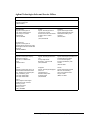
11923A 1.0 mm
Connector Launch Assembly
Operating and Service
Manual
Agilent Part Number: 11923-90001
Printed in USA
February 2001
Supersedes: March 1999
Notice
The information contained in this document is subject to change without
notice.
Agilent Technologies makes no warranty of any kind with regard to this
material, including, but not limited to, the implied warranties of
merchantability and fitness for a particular purpose. Agilent Technologies
shall not be liable for errors contained herein or for incidental or
consequential damages in connection with the furnishing, performance, or
use of this material.
Agilent Technologies assumes no responsibility for the use or reliability of
its software on equipment that is not furnished by Agilent Technologies.
This document contains proprietary information which is protected by
copyright. All rights are reserved. No part of this document may be
photocopied, reproduced, or translated to another language without prior
written consent of Agilent Technologies.
Restricted Rights Legend
Use, duplication, or disclosure by the U.S. Government is subject to
restrictions as set forth in subparagraph (c)(1)(ii) of the Rights in Technical
Data and Computer Software clause at DFARS 252.227-7013 for DOD
agencies, and subparagraphs (c)(1) and (c)(2) of the Commercial Computer
Software Restricted Rights clause at FAR 52.227-19 for other agencies.
Agilent Technologies, Inc
Santa Rosa Systems Division
1400 Fountaingrove Parkway
Santa Rosa, CA 95403-1799, U.S.A.
© Copyright 1999, 2001
Agilent Technologies, Inc.
ii Agilent Technologies 11923A Launch Assembly Operating and Service Manual
Warranty
Certification
Agilent Technologies certifies that this product met its published
specifications at the time of shipment from the factory. Agilent Technologies
further certifies that its calibration measurements are traceable to the
United States National Institute of Standards and Technology (NIST,
formerly NBS), to the extent allowed by the Institute’s calibration facility,
and to the calibration facilities of other International Standards
Organization members.
Warranty
This Agilent Technologies system product is warranted against defects in
materials and workmanship for a period corresponding to the individual
warranty periods of its component products. Instruments are warranted for a
period of one year. During the warranty period, Agilent Technologies will, at
its option, either repair or replace products that prove to be defective.
Warranty service for products installed by Agilent Technologies and certain
other products designated by Agilent Technologies will be performed at
Buyer’s facility at no charge within Agilent Technologies service travel
areas. Outside Agilent Technologies service travel areas, warranty service
will be performed at Buyer’s facility only upon Agilent Technologies’s prior
agreement and Buyer shall pay Agilent Technologies’s round trip travel
expenses. In all other areas, products must be returned to a service facility
designated by Agilent Technologies.
For products returned to Agilent Technologies for warranty service, Buyer
shall prepay shipping charges to Agilent Technologies and Agilent
Technologies shall pay shipping charges to return the product to Buyer.
However, Buyer shall pay all shipping charges, duties, and taxes for products
returned to Agilent Technologies from another country.
Agilent Technologies warrants that its software and firmware designated by
Agilent Technologies for use with an instrument will execute its
programming instructions when properly installed on that instrument.
Agilent Technologies does not warrant that the operation of the instrument,
or software, or firmware will be uninterrupted or error free.
LIMITATION OF WARRANTY. The foregoing warranty shall not apply
to defects resulting from improper or inadequate maintenance by Buyer,
Buyer-supplied software or interfacing, unauthorized modification or
misuse, operation outside of the environmental specifications for the
product, or improper site preparation or maintenance.
Agilent Technologies 11923A Launch Assembly Operating and Service Manual iii
NO OTHER WARRANTY IS EXPRESSED OR IMPLIED. AGILENT
TECHNOLOGIES SPECIFICALLY DISCLAIMS THE IMPLIED
WARRANTIES OR MERCHANTABILITY AND FITNESS FOR A
PARTICULAR PURPOSE.
EXCLUSIVE REMEDIES. THE REMEDIES PROVIDED HEREIN ARE
BUYER’S SOLE AND EXCLUSIVE REMEDIES. AGILENT
TECHNOLOGIES SHALL NOT BE LIABLE FOR ANY DIRECT,
INDIRECT, SPECIAL, INCIDENTAL, OR CONSEQUENTIAL
DAMAGES, WHETHER BASED ON CONTRACT, TORT, OR ANY
OTHER LEGAL THEORY.
Assistance
Product maintenance agreements and other customer assistance agreements
are available for Agilent Technologies products.
For assistance, call your local Agilent Technologies Sales and Service Office
(refer to “Agilent Technologies Sales and Service Offices” on page v.)
iv Agilent Technologies 11923A Launch Assembly Operating and Service Manual
Agilent Technologies Sales and Service Offices
UNITED STATES
Instrument Support Center
Agilent Technologies
(800) 403-0801
EUROPEAN FIELD OPERATIONS
Headquarters
Agilent Technologies S.A.
150, Route du Nant-d’Avril
1217 Meyrin 2/ Geneva
Switzerland
(41 22) 780.8111
France
Agilent Technologies France
1 Avenue Du Canada
Zone D’Activite De Courtaboeuf
F-91947 Les Ulis Cedex
France
(33 1) 69 82 60 60
Germany
Agilent Technologies GmbH
Agilent Technologies Strasse
61352 Bad Homburg v.d.H
Germany
(49 6172) 16-0
Great Britain
Agilent Technologies Ltd.
Eskdale Road, Winnersh Triangle
Wokingham, Berkshire RG41 5DZ
England
(44 118) 9696622
INTERCON FIELD OPERATIONS
Headquarters
Agilent Technologies Company
3495 Deer Creek Rd.
Palo Alto, CA 94304-1316
USA
(415) 857-5027
Australia
Agilent Technologies Australia
Ltd.
31-41 Joseph Street
Blackburn, Victoria 3130
(61 3) 895-2895
Canada
Agilent Technologies (Canada) Ltd.
17500 South Service Road
Trans-Canada Highway
Kirkland, Quebec H9J 2X8
Canada
(514) 697-4232
Japan
Agilent Technologies Japan, Ltd.
Measurement Assistance Center
9-1, Takakura-Cho, Hachioji-Shi,
Tokyo 192-8510, Japan
TEL (81) -426-56-7832
FAX (81) -426-56-7840
Singapore
Agilent Technologies Singapore
(Pte.) Ltd.
150 Beach Road
#29-00 Gateway West
Singapore 0718
(65) 291-9088
Taiwan
Agilent Technologies Taiwan
8th Floor, H-P Building
337 Fu Hsing North Road
Taipei, Taiwan
(886 2) 712-0404
China
China Agilent Technologies
38 Bei San Huan X1 Road
Shuang Yu Shu
Hai Dian District
Beijing, China
(86 1) 256-6888
Agilent Technologies 11923A Launch Assembly Operating and Service Manual v
Safety and Regulatory Information
Safety and Regulatory Information
Review this product and related documentation to familiarize yourself with
safety markings and instructions before you operate the instrument. This
product has been designed and tested in accordance with international
standards.
WARNING
The WARNING notice denotes a hazard. It calls attention to a procedure,
practice, or the like, that, if not correctly performed or adhered to, could result
in personal injury. Do not proceed beyond a WARNING notice until the
indicated conditions are fully understood and met.
CAUTION
The CAUTION notice denotes a hazard. It calls attention to an operating
procedure, practice, or the like, which, if not correctly performed or adhered
to, could result in damage to the product or loss of important data. Do not
proceed beyond a CAUTION notice until the indicated conditions are fully
understood and met.
Instrument Markings
!
When you see this symbol on your instrument, you should refer to the instrument’s
instruction manual for important information.
This symbol indicates hazardous voltages.
The laser radiation symbol is marked on products that have a laser output.
This symbol indicates that the instrument requires alternating current (ac) input.
The CE mark is a registered trademark of the European Community. If it is
accompanied by a year, it indicates the year the design was proven.
The CSA mark is a registered trademark of the Canadian Standards Association.
1SM1-A
This text indicates that the instrument is an Industrial Scientific and Medical Group 1
Class A product (CISPER 11, Clause 4).
This symbol indicates that the power line switch is ON.
This symbol indicates that the power line switch is OFF or in STANDBY position.
vi Agilent Technologies 11923A Launch Assembly Operating and Service Manual
Contents
Notice . . . . . . . . . . . . . . . . . . . . . . . . . . . . . . . . . . . . . . . . . . . . . . . . . . . . . .ii
Warranty . . . . . . . . . . . . . . . . . . . . . . . . . . . . . . . . . . . . . . . . . . . . . . . . . . . iii
Certification . . . . . . . . . . . . . . . . . . . . . . . . . . . . . . . . . . . . . . . . . . . . . iii
Warranty . . . . . . . . . . . . . . . . . . . . . . . . . . . . . . . . . . . . . . . . . . . . . . . . iii
Assistance . . . . . . . . . . . . . . . . . . . . . . . . . . . . . . . . . . . . . . . . . . . . . . . iv
Agilent Technologies Sales and Service Offices . . . . . . . . . . . . . . . . . v
Safety and Regulatory Information . . . . . . . . . . . . . . . . . . . . . . . . . . . . . . . vi
1.
General Information
Connector Launch Overview . . . . . . . . . . . . . . . . . . . . . . . . . . . . . . . . . . 1-1
Serial Numbers . . . . . . . . . . . . . . . . . . . . . . . . . . . . . . . . . . . . . . . . . . 1-1
Incoming Inspection . . . . . . . . . . . . . . . . . . . . . . . . . . . . . . . . . . . . . . 1-2
Clarifying Connector Sex . . . . . . . . . . . . . . . . . . . . . . . . . . . . . . . . . . 1-2
Figure 1-1. Male and Female Connectors . . . . . . . . . . . . . . . . . . . . 1-2
2.
Specifications
Electrical Specifications . . . . . . . . . . . . . . . . . . . . . . . . . . . . . . . . . . . . . . 2-1
Supplemental Characteristics . . . . . . . . . . . . . . . . . . . . . . . . . . . . . . . . . . 2-1
Table 2-1. Electrical Specifications . . . . . . . . . . . . . . . . . . . . . . . . . . 2-1
Table 2-2. Supplemental Electrical Characteristics . . . . . . . . . . . . . 2-1
Table 2-3. Supplemental Mechanical Characteristics . . . . . . . . . . . . 2-2
Environmental Requirements . . . . . . . . . . . . . . . . . . . . . . . . . . . . . . . . . . 2-3
Table 2-4. Environmental Requirements . . . . . . . . . . . . . . . . . . . . . . 2-3
Temperature—What To Watch Out For . . . . . . . . . . . . . . . . . . . . . . . 2-3
3.
Mounting the Launch
Creating the Package or Fixture Wall . . . . . . . . . . . . . . . . . . . . . . . . . 3-1
Figure 3-1. Section View of Machining Detail for the Package Wall 3-1
Threading the Launch into the Package or Fixture . . . . . . . . . . . . . . 3-2
Mounting the Circuit Inside the Package . . . . . . . . . . . . . . . . . . . . . . 3-2
Figure 3-2. Circuit Mounting Detail . . . . . . . . . . . . . . . . . . . . . . . . . 3-3
4.
Making Connections
Electrostatic Discharge . . . . . . . . . . . . . . . . . . . . . . . . . . . . . . . . . . . . 4-1
Preventive Maintenance . . . . . . . . . . . . . . . . . . . . . . . . . . . . . . . . . . . 4-1
Visual Inspection . . . . . . . . . . . . . . . . . . . . . . . . . . . . . . . . . . . . . . . . . . . 4-2
Required Inspection Tools . . . . . . . . . . . . . . . . . . . . . . . . . . . . . . . . . 4-2
Obvious Defects or Damage . . . . . . . . . . . . . . . . . . . . . . . . . . . . . . . . 4-2
Connector Contacts . . . . . . . . . . . . . . . . . . . . . . . . . . . . . . . . . . . . . . 4-3
Figure 4-1. Contact Integrity . . . . . . . . . . . . . . . . . . . . . . . . . . . . . . 4-3
Concentricity . . . . . . . . . . . . . . . . . . . . . . . . . . . . . . . . . . . . . . . . . . . 4-3
Figure 4-2. Concentricity - Female Connector . . . . . . . . . . . . . . . . 4-3
Agilent Technologies 11923A Launch Assembly Operating and Service Manual Contents 1
Figure 4-3. Concentricity - Male Connector . . . . . . . . . . . . . . . . . . 4-4
Mating Plane Surfaces . . . . . . . . . . . . . . . . . . . . . . . . . . . . . . . . . . . 4-4
Damaged Connectors . . . . . . . . . . . . . . . . . . . . . . . . . . . . . . . . . . . . 4-4
Connector Wear . . . . . . . . . . . . . . . . . . . . . . . . . . . . . . . . . . . . . . . . . 4-4
Pin Depth . . . . . . . . . . . . . . . . . . . . . . . . . . . . . . . . . . . . . . . . . . . . . . . . . 4-5
Protrusion and Recession . . . . . . . . . . . . . . . . . . . . . . . . . . . . . . . . . 4-5
Figure 4-4. Connector Pin Depth . . . . . . . . . . . . . . . . . . . . . . . . . . 4-5
Connector Alignment . . . . . . . . . . . . . . . . . . . . . . . . . . . . . . . . . . . . . . . 4-6
Figure 4-5. Alignment . . . . . . . . . . . . . . . . . . . . . . . . . . . . . . . . . . 4-7
Connector Misalignment . . . . . . . . . . . . . . . . . . . . . . . . . . . . . . . . . . 4-7
Figure 4-6. Forced Misalignment . . . . . . . . . . . . . . . . . . . . . . . . . . 4-7
Cleaning Connectors . . . . . . . . . . . . . . . . . . . . . . . . . . . . . . . . . . . . . . . . 4-8
Supplies and Equipment Needed . . . . . . . . . . . . . . . . . . . . . . . . . . . 4-8
Basic Cleaning Procedure . . . . . . . . . . . . . . . . . . . . . . . . . . . . . . . . . 4-8
Figure 4-7. Cleaning Illustration . . . . . . . . . . . . . . . . . . . . . . . . . . 4-8
Connection Procedure . . . . . . . . . . . . . . . . . . . . . . . . . . . . . . . . . . . . . . . 4-9
Connection Procedure . . . . . . . . . . . . . . . . . . . . . . . . . . . . . . . . . . . . 4-9
Using the Torque Wrench . . . . . . . . . . . . . . . . . . . . . . . . . . . . . . . . . . . 4-10
Required Wrenches . . . . . . . . . . . . . . . . . . . . . . . . . . . . . . . . . . . . . 4-10
Table 4-1. Torque Wrench Information . . . . . . . . . . . . . . . . . . . . 4-10
Torque Wrench Procedure . . . . . . . . . . . . . . . . . . . . . . . . . . . . . . . . 4-10
Disconnection Procedure . . . . . . . . . . . . . . . . . . . . . . . . . . . . . . . . . . . . 4-11
Handling and Storage . . . . . . . . . . . . . . . . . . . . . . . . . . . . . . . . . . . . . . 4-12
5.
Replaceable Parts
Table 5-1. Replaceable Parts . . . . . . . . . . . . . . . . . . . . . . . . . . . . . . 5-1
Contents 2 Agilent Technologies 11923A Launch Assembly Operating and Service Manual
1
General Information
Connector Launch Overview
The 11923A 1.0-mm female connector launch assembly is designed for
ultra-high frequency (up to 110 GHz) coaxial signal transmission into a
microstrip package. The launch assembly facilitates designing, building,
testing, and troubleshooting high-frequency microcircuits, components, and
custom prototypes.
The launch assembly threads into a package or fixture housing. The user is
responsible for the machining of the package and installing the launch into
the package. Procedures describing the necessary geometry for machining
the package wall and instructions for mounting the launch are given in
Chapter 3.
The launch assembly features a 1.0-mm female connector on one end and a
gold-plated pin interface to the microcircuit on the other.
Serial Numbers
•
The 1.0-mm center conductor is supported by a low-loss plastic bead.
The connector interface utilizes an air dielectric for the highest accuracy
and repeatability, and is designed to meet or exceed the IEE Std 287
Precision Coaxial Connector GPC grade specifications.
•
The launch assembly contains a glass-to-metal seal soldered inside the
launch housing. The gold-plated pin on the launch extends inside the
package or fixture for connection onto the circuit.
A serial number label is attached to the foam-lined box containing the
launch. The serial number is made up of five numbers and is unique to each
adapter.
Agilent Technologies 11923A Launch Assembly Operating and Service Manual 1-1
General Information
Incoming Inspection
Clarifying Connector
Sex
Agilent Technologies will arrange for repair or replacement of incomplete or
damaged shipments without waiting for a settlement from the transportation
company. When you send a device to Agilent Technologies, include the
following information:
•
•
Your company name and address.
•
If you are returning one or more devices, include the part numbers and
serial numbers.
•
•
Indicate the type of service required.
A technical contact person within your company, and the person’s
complete phone number.
Include any applicable information.
In this manual, connectors are referred to in terms of their device sex.
Male Connector
Female Connector
Figure 1-1 Male and Female Connectors
1-2 Agilent Technologies 11923A Launch Assembly Operating and Service Manual
2
Specifications
Electrical Specifications
Electrical specifications are performance standards or limits against which
the launch assemblies are tested.
Table 2-1
Electrical Specifications
Insertion loss
Frequency
Value
dc to 110 GHz
–1.0 dB
Supplemental Characteristics
Supplemental characteristics are values which are typically met by the
majority of the launches tested at agilent Technologies. These supplemental
characteristics are intended to provide useful information. They are typical
but non-warranted performance parameters.
Center Conductor Protrusion and Pin Depth
The supplemental mechanical characteristics such as center conductor
protrusion and pin depth are important supplemental characteristics related
to electrical performance. Pin depth is measured mechanically and verified
by electrical testing. This ensures that the 1.0-mm connector does not exhibit
any center conductor protrusion and has proper pin depth when it leaves the
factory.
Table 2-2
Supplemental Electrical Characteristics
Characteristic
Frequency
Typical Value
Return loss
dc to 110 GHz
–16 dB
Maximum power
dc to 110 GHz
6W
Agilent Technologies 11923A Launch Assembly Operating and Service Manual 2-1
Specifications
Reference Plane to
Reference Plane
Table 2-3
Supplemental Mechanical Characteristics
Characteristic
Typical Value
Inside diameter of 1.0-mm outer conductor
1.000 ± 0.005 mm
Outside diameter of center conductor
0.434 ± 0.005 mm
Length of outer conductors1
10.34 mm (nominal)
Inside diameter of launch body feedthru
0.38 ± 0.010 mm
Outside diameter of launch pin
0.162 ± 0.005 mm
1.0-mm female connector pin depth
0 (flush) to 0.025 mm
(maximum recession)
Launch pin extension
0.32 ± 0.05 mm
Flatness of reference plane
0.010 mm (worst case)
Flatness of end of launch body
0.010 mm (worst case)
1. Reference place to reference plane
2-2 Agilent Technologies 11923A Launch Assembly Operating and Service Manual
Specifications
Environmental Requirements
Table 2-4
Environmental Requirements
Parameter
Required Values/Ranges
Operating temperature
0 to 55 °C (32 tο 131 °F)
Storage temperature
–40 to +75 °C (–40 to +167 °F)
Altitude
Operation
Storage
< 15,000 meters (≈ 50,000 feet)
< 15,000 meters (≈ 50,000 feet)
Relative humidity
Operation
Storage
Always non-condensing
0 to 80% (26 °C maximum dry bulb)
0 to 90%
Temperature—What
To Watch Out For
Due to the critical dimensions and tight tolerances of the 1.0-mm connector,
electrical characteristics will change with temperature. The operating
temperature is a critical factor in the performance during measurements and
between calibrations.
CAUTION
Remember your fingers are a heat source, so avoid handling the devices
unnecessarily.
Agilent Technologies 11923A Launch Assembly Operating and Service Manual 2-3
3
Mounting the Launch
Creating the Package
or Fixture Wall
The launch is designed to be threaded into a 5-mm thick package wall. The
user is responsible for machining the package and installing the launch.
Figure 3-1 shows the machining detail for creating the package wall.
5.0 0.05
M7 x 0.75 6H
Centerline Offset
-A4.50 0.01
3.2 Min
5.15
1.65 0.10
0.05
0.01 A S
Figure 3-1
Section View of Machining Detail for the Package Wall
The following machining details are recommended to provide optimum
connections. All measurements are in millimeters (mm).
•
•
The bottom of the 4.50 diameter hole must be flat for proper grounding.
•
The centerline offset between the threaded and the package floor is
calculated as follows:
The edge between the package floor and the 4.50 diameter hole must be
carefully deburred with a minimum corner break.
Offset = substrate thickness + 0.081 (radius of pin) + 0.075 (clearance
for solder flow)
•
Gold plating is recommended for conductivity and corrosion protection.
Agilent Technologies 11923A Launch Assembly Operating and Service Manual 3-1
Mounting the Launch
Threading the Launch
into the Package or
Fixture
If you need a quasi-hermetic seal or you want to permanently retain the
launch assembly in the package or fixture, epoxy may be applied to the
threads of the launch prior to installation. Use heat to cure the epoxy, if
necessary.
CAUTION
Do not overheat. The dielectric material in the support bead is capable of
withstanding 125 °C for prolonged periods and 150 °C for short periods.
1. Hand thread the launch all the way into the package or fixture wall and
then reverse thread 1/8 turn or 45 degrees of rotation to allow for final
tightening with a torque wrench.
2. Use a 7-mm torque wrench* on the hex portion of the launch body to
thread it into the package wall. Tighten the launch into the package with
56 N-cm (5 in-lb) of torque. Refer to “Using the Torque Wrench” on
page 4-10 for the recommended procedure.
This is enough to create a slight deformation where the launch contacts
the package floor to assure a good ground connection.
* This torque wrench is not available from Agilent Technologies. Refer to Table 5-1
for supplier information.
Mounting the Circuit
Inside the Package
1. Clean all surfaces with alcohol and blow them dry with filtered
compressed air.
2. For the best match, place the edge of the circuit 0.022 ± 0.008 mm from
the end of the outer body of the launch. Refer to Figure 3-2.
3. Slide the circuit under the launch pin. Align it so that the launch pin is
directly over the signal trace.
4. Affix the circuit to the package body with electrically conductive epoxy.
CAUTION
Do not overheat. The dielectric material in the support bead is capable of
withstanding 125 °C for prolonged periods and 150 °C for short periods.
3-2 Agilent Technologies 11923A Launch Assembly Operating and Service Manual
Mounting the Launch
5. Complete the signal path by soldering the launch pin to the signal trace.
OR
Complete the signal path by gold ribbon bond attachment. For best
performance, size the gold ribbon to match the dimensions of the launch
pin and the signal trace.
NOTE
If solder is used, it is important to control the volume of the solder flow to
match the size of the launch pin and the signal trace. Be careful to avoid too
much solder (capacitive) or too little (inductive).
Side View
End View
Package Wall
Launch Body
Launch Pin
Solder
Circuit
Solder
Ground Plane
0.022 ± 0.008
Figure 3-2
Signal Trace
Circuit Mounting Detail
Agilent Technologies 11923A Launch Assembly Operating and Service Manual 3-3
4
Making Connections
Electrostatic Discharge
Protection against ESD (electrostatic discharge) is essential while cleaning,
inspecting, or connecting any connector attached to a static–sensitive circuit
(such as those found in test sets).
Static electricity builds up on the body, and can easily damage sensitive
internal circuit elements when discharged by contact with the center
conductor of a connector. Static discharges too small to be felt can cause
permanent damage. Devices such as calibration and verification
components, and devices under test can also carry an electrostatic charge.
Preventive
Maintenance
•
Always have a grounded antistatic mat in front of your test equipment
and wear a grounded wrist strap attached to it.
•
Ground yourself before you clean, inspect, or make a connection to a
static–sensitive device or test port. You can, for example, grasp the
grounded outer shell of the test port briefly to discharge static from your
body.
•
Discharge static electricity from a device before connecting it. Touch the
device briefly (through a resistor of at least 1 M Ω) to either the outer
shell of the test port, or to another exposed ground. This discharges static
electricity and protects test equipment circuitry.
The best techniques for maintaining the integrity of 1.0-mm connectors is to
include routine visual inspection (using 10X magnification), cleaning, and
proper connection techniques using the procedures in the following sections.
Failure to detect and remove dirt or metallic particles on a mating plane
surface can degrade repeatability and accuracy, and can damage any
connector mated to it. Improper connections resulting from poor connection
techniques can also damage these devices.
Connector cleaning supplies and electrostatic discharge safety supplies are
not provided but can be ordered separately. For cleaning and inspection, a
10X magnifying glass is available. (Refer to Chapter 5, “Replaceable Parts”
for ordering information.)
Agilent Technologies 11923A Launch Assembly Operating and Service Manual 4-1
Making Connections
Visual Inspection
Visual Inspection
Visual inspection, and if necessary, cleaning should be done every time a
connection is made. Metal particles from the connector threads may fall into
the connector when it is disconnected. One connection made with a dirty or
damaged connector can damage both connectors beyond repair.
Required Inspection
Tools
A minimum magnification of 10X is required to inspect the mating surfaces,
connector contacts, and concentricity of the 1.0-mm connectors. It is also
necessary to use good lighting (such as a halogen task light) to see the
damage on a connector. Use the guidelines in “Obvious Defects or Damage”
when evaluating the integrity of your connectors.
Obvious Defects or
Damage
Examine the connectors first for obvious defects or damage:
•
Plating
▲
▲
•
•
Bare metal showing
Burrs or blisters
Deformed threads
Center Conductors
▲
▲
▲
▲
Bent
Broken
Misaligned
Concentricity
Connector nuts should move smoothly and be free of:
▲
▲
▲
Burrs
Loose metal particles
Rough spots
Any connector that has obvious defects should be discarded. See Figure 4-1,
Figure 4-2, and Figure 4-3 for visual inspection guidelines.
4-2 Agilent Technologies 11923A Launch Assembly Operating and Service Manual
Making Connections
Visual Inspection
Connector Contacts
Refer to Figure 4-1 for visual guidelines to aid you in evaluating the contact
integrity of a connector.
Take careful note of the location of the cross hairs in relationship to the
center of the following figures.
Perfectly formed,
new contact
Normal wear will
spread contact slightly
Damaged contact will
look electrically
capacitive
Figure 4-1 Contact Integrity
Concentricity
Perfectly concentric
Figure 4-2 and Figure 4-3 show the concentricity of both the male and
female 1.0-mm connectors.
.025 mm off-center
specification maximum
>.025 mm off-center
DO NOT USE
Figure 4-2 Concentricity - Female Connector
Agilent Technologies 11923A Launch Assembly Operating and Service Manual 4-3
Making Connections
Visual Inspection
.025 mm off-center
specification maximum
Perfectly concentric
Figure 4-3
Mating Plane Surfaces
> .025 mm off-center
DO NOT USE
Concentricity - Male Connector
Flat contact between the connectors at all points on their mating plane
surface is required for a good connections.
Look for deep scratches or dents, and for dirt and metal particles on the
connector mating plane surfaces. Also look for “dings” on the mating plane
surfaces of the center and outer conductors, and for signs of damage due to
misalignment and excessive or uneven wear.
A light burnishing of the mating plane surface is normal. This is evident as
light scratches, or shallow circular marks distributed more or less uniformly
over the mating plane surface. Other small defects and cosmetic
imperfections are also normal. None of these affect electrical or mechanical
performance.
Clean and inspect the connector again if it shows:
•
•
•
Deep scratches or dents
Particles clinging to the mating plane surface
Uneven wear
Damaged Connectors
Before you connect a new, undamaged connector in the same configuration,
try to determine the cause of the damaged connector to eliminate other
connector problems. Damaged connectors should be discarded.
Connector Wear
Connector wear eventually degrades performance. The more use a connector
gets, the faster it wears and degrades. The wear is greatly accelerated when
connectors are not kept clean. When your connectors become worn, replace
them.
4-4 Agilent Technologies 11923A Launch Assembly Operating and Service Manual
Making Connections
Pin Depth
Pin Depth
Pin depth is the distance that the center conductor mating plane differs from
being flush with the outer conductor mating plane. The pin depth of a
connector can be in one of two states, either protruding or recessed.
Protrusion and
Recession
•
NOTE
At no time should the pin depth of the 1.0 mm connector be protruding.
•
Protrusion - the center conductor extends beyond the outer conductor
mating plane.
Recession - the center conductor is set back from the outer conductor
mating plane.
The pin depth value of each connector was verified to be within factory
specifications at shipment. The electrical performance of the connector
depends, to some extent, on its pin depth. The electrical specifications take
into account the effect of pin depth on the performance of the connector.
Figure 4-4 shows a visual representation of proper pin depth (slightly
recessed).
Male
Female
Outer
Conductor
Center
Conductor
Male Pin Depth
Outer Conductor
Mating Plane
Female Pin Depth
Outer Conductor
Mating Plane
Figure 4-4 Connector Pin Depth
Agilent Technologies 11923A Launch Assembly Operating and Service Manual 4-5
Making Connections
Connector Alignment
Connector Alignment
Good connections require a skilled operator. Instrument sensitivity and
coaxial connector mechanical tolerances are such that slight errors in
operator technique can have a significant effect on measurements and
measurement uncertainties.
NOTE
The most common cause of measurement error is poor connections.
Follow these recommendations for optimum connection technique:
1. Clean and inspect (visually and mechanically) all of your connectors.
2. Carefully align the connectors. Look for flat physical contact at all
points on the mating plane surfaces.
NOTE
If one of the 1.0-mm connectors is free to move, self-alignment is possible
during connection. Self-alignment occurs because outer conductors engage
before the center conductors (refer to Figure 4-5 and Figure 4-6).
3. Make a gentle, preliminary connection.
4. When making a connection, turn only the connector nut. Do not rotate a
device when you make a connection, and do not apply a lateral or
horizontal (bending) force.
5. Use an open–end wrench to keep the device from rotating when you
make a final connection with the torque wrench.
4-6 Agilent Technologies 11923A Launch Assembly Operating and Service Manual
Making Connections
Connector Alignment
Figure 4-5 Alignment
Connector
Misalignment
Forced misalignment could damage the female center conductor.
Figure 4-6 Forced Misalignment
NOTE
To achieve misalignment as shown in Figure 4-6 you must use excessive
force.
Agilent Technologies 11923A Launch Assembly Operating and Service Manual 4-7
Making Connections
Cleaning Connectors
Cleaning Connectors
Supplies and
Equipment Needed
The supplies and equipment that are needed to perform the cleaning
procedures, and their Agilent Technologies part numbers are listed in
Table 5-1 on page 5-1.
NOTE
A minimum magnification of 10X is required for all inspections of the
1.0-mm connector parts.
Basic Cleaning
Procedure
1. Inspect the connector for dust, dirt, metal fragments, oils or films, and
debris.
2. Blow off any dust with a filtered, clean supply of compressed air.
3. Add a few drops of high-purity isopropyl alcohol to small cleaning swab
(do not apply alcohol directly to the parts).
NOTE
When using isopropyl alcohol to clean connectors do not allow liquid to flow
down inside the connector. This may cause measurement errors due to
residue inside the connector. If possible keep the connector facing down.
4. Gently wipe connecting surfaces with the end of the cleaning swab (refer
to Figure 4-7).
5. Blow dry with a clean supply of compressed air.
6. Inspect and repeat cleaning procedure if necessary.
Figure 4-7 Cleaning Illustration
4-8 Agilent Technologies 11923A Launch Assembly Operating and Service Manual
Making Connections
Connection Procedure
Connection Procedure
Connection Procedure
1. Ground yourself and all devices (wear a grounded wrist strap and work
on an antistatic mat).
2. Visually inspect the connectors (refer to “Visual Inspection” on
page 4-2).
3. If necessary, clean the connectors (refer to “Cleaning Connectors” on
page 4-8).
4. Carefully align the connectors. The male connector center pin must slip
concentrically into the contact fingers of the female connector (refer to
Figure 4-5 and Figure 4-6).
5. Push the connectors straight together. Do not twist or screw them
together. As the center conductors mate, there is usually a slight
resistance.
CAUTION
Do not twist one connector into the other (like inserting a light bulb). This
happens when you turn the device body, rather than the connector nut. Major
damage to the center conductor and the outer conductor can occur if the
device body is twisted.
6. Initial tightening can be done by hand, or with an open-end wrench.
Tighten until “snug” or where the connectors are first making contact.
The preliminary connection is tight enough when the mating plane
surfaces make uniform, light contact. Do not overtighten this
connection.
At this point, all you want is for the outer conductors to make gentle
contact on both mating surfaces. Use very light finger pressure (no more
than 2 in-lbs of torque).
7. Relieve any side pressure on the connection from long or heavy devices
or cables. This assures consistent torque (refer to “Using the Torque
Wrench” on page 4-10).
Agilent Technologies 11923A Launch Assembly Operating and Service Manual 4-9
Making Connections
Using the Torque Wrench
Using the Torque Wrench
Using the torque wrench guarantees that a connection is not too tight. This
will help prevent possible connector damage. It also guarantees that all
connections are equally tight each time.
CAUTION
1. Static friction must not be present during torquing.
2. Do not pre-tighten so much that there is no rotation of the nut with the
torque wrench. Leave about 1/8 turn or 45 degrees of rotation for the
final tightening with the torque wrench.
3. Rotate only the connector nut when you tighten the connector. Use an
open–end wrench to keep the body of the device from turning.
Required Wrenches
Table 4-1 provides information on the torque wrench required for making
1.0-mm connections and for the threading the launch into the package wall.
Refer to Table 5-1 on page 5-1 for ordering information and part numbers.
Table 4-1 Torque Wrench Information
Torque Wrench
Procedure
Connector
Type
Torque
Setting
Torque
Tolerance
1.0 mm
45 N–cm (4 in–lb)
±5.4 N–cm (±0.5 in–lb)
Launch installation
56 N–cm (5 in–lb)
±5.4 N–cm (±0.5 in–lb)
Backup
Wrench
6 mm/7 mm
•
To thread the launch into the package wall, use a 7-mm torque wrench
on the hex portion of the launch and tighten the launch into the package
wall with 56 N-cm (5 in-lb) of torque.
•
To make 1.0-mm connections to the launch, use a 6-mm torque wrench
to apply the recommended torque to the 1.0-mm male nut while holding
the hex portion of the launch with a 7-mm open-end backup wrench.
•
To make other 1.0-mm connections, use a 6-mm torque wrench and
6-mm backup wrench (refer to “Connection Procedure” on page 4-9).
4-10 Agilent Technologies 11923A Launch Assembly Operating and Service Manual
Making Connections
Disconnection Procedure
Disconnection Procedure
To avoid lateral (bending) force on the connector mating plane surfaces,
always support the devices and connections.
1. Use an open–end wrench to prevent the device body from turning.
2. Use another wrench to loosen the connector nut.
3. Complete the disconnection by hand, turning only the connector nut.
CAUTION
Do not twist one connector out of the other, (like removing a light bulb).
Turn the connector nut, not the device body. Major damage to the center
conductor and the outer conductor can occur if the device body is twisted.
4. Pull the connectors straight apart without twisting or bending.
Agilent Technologies 11923A Launch Assembly Operating and Service Manual 4-11
Making Connections
Handling and Storage
Handling and Storage
•
Store the connector launch assembly in the original foam–lined box
which has the serial number label attached to it.
•
Never store the assembly loose in a box, in a desk, or in a bench drawer.
This is the most common cause of connector damage during storage.
•
•
Keep connectors clean.
•
Do not set connectors contact–end down on a hard surface. The plating
and the mating plane surfaces can be damaged if the interface comes in
contact with any hard surface.
Do not touch mating plane surfaces. Natural skin oils and microscopic
particles of dirt are easily transferred to the connector interface and are
very difficult to remove.
4-12 Agilent Technologies 11923A Launch Assembly Operating and Service Manual
Replaceable Parts
5
Replaceable Parts
NOTE
There are no internal replaceable parts within the launch. The 1.0-mm
connector is not considered field repairable. If a unit is in need of repair, a
replacement must be purchased.
The following table lists the part numbers necessary for inspection,
connection, and ESD protection. To order a listed part, note the description,
part number, and the quantity desired. Telephone or send your order to the
nearest Agilent Technologies sales and service office listed in page -v.
Table 5-1
Replaceable Parts
Description
Part Number
Items Included With Launch
Operating and Service Manual
11923-90001
Items Not Included With Launch
10X magnifying glass
1000–1114
6-mm 4 in-lb torque wrench
8710–2079
6-mm open-end wrench
8710–2156
7-mm 5 in-lb torque wrench
TB OE 7-mm 5lbf-in1
7-mm open-end wrench
8710–1761
Cleaning swabs
9300–1745
Isopropyl alcohol (30 ml)
8500–5344
Grounding wrist strap
9300–1367
5-foot grounding cord (for wrist strap)
9300–0980
2 x 4 foot conductive table mat and 15-ft ground wire
9300–0797
ESD heel strap (for conductive floors)
9300–1126
1. Not available from Agilent Technologies. This part number may be ordered from Mountz, San Jose,
CA.
Agilent Technologies 11923A Launch Assembly Operating and Service Manual 5-1
Index
A
H
assembling the package wall, 3-1
handling and storage, 4-12
C
I
center conductor
protrusion and pin depth, 2-1
characteristics
supplemental mechanical, 2-1
completing the signal path, 3-3
connections
alignment, 4-6
process, 4-9
connector contacts, 4-3
connectors
clarifying sex, 1-2
cleaning, 4-8
damaged, 4-4
defects or damage, 4-2
mating plane surface, 4-4
insertion loss, 2-1
inspection
incoming, 1-2
visual, 4-2
L
launch
creating the package wall, 3-1
overview, 1-1
M
maintenance, preventive, 4-1
making connections, 4-1
mating plane surfaces, 4-4
mounting the circuit, 3-2
mounting the launch, 3-1
D
damaged connectors, 4-4
disconnection procedure, 4-11
P
E
electrostatic discharge, 4-1
environmental requirements, 2-1
F
figure
adapter dimensions, 2-1
alignment, 4-7
circuit mounting detail, 3-3
cleaning illustration, 4-8
concentricity female connector, 4-3
concentricity male connector, 4-4
connector pin depth, 4-5
contact integrity, 4-3
machining detail for mounting the launch, 3-1
male and female connectors, 1-2
misalignment, 4-7
package wall
assembly instructions, 3-1
machining detail, 3-1
parts, replacing, 5-1
pin depth
protrusion, 4-5
recession, 4-5
visual, 4-5
R
repeatability, 2-1
replaceable parts, 5-1
return loss, 2-1
S
serial numbers, 1-1
specifications, 2-1
electrical, 2-1
Agilent Technologies 11923A Launchy Assembly Operating and Service Manual Index 1
T
temperature, operating, 2-1
torque wrench
procedure for using, 4-10
settings and tolerance, 4-10
V
visual inspection
concentricity, 4-3
connector wear, 4-4
contact integrity, 4-3
mating plane surfaces, 4-4
obvious defects or damage, 4-2
required tools, 4-2
Index 2 Agilent Technologies 11923A Launchy Assembly Operating and Service Manual