1
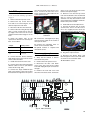
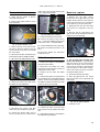
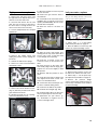
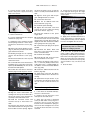
MAC 2000 Wash
service manual
MAC 2000 Wash Service Manual
PROCEDURES
Head procedures
Yoke procedures
Base procedures
CMYC belts and flags, replace . . . . 12
CMYC module, install . . . . . . . . . . . . 5
CMYC module, remove . . . . . . . . . . . 5
CMYC module, separate . . . . . . . . . 11
CMYC motors, replace . . . . . . . . . . 13
Color wheel 1 belt, replace . . . . . . . . 6
Color wheel 1 motor, replace . . . . . . . 6
Color wheel 2 belt, replace . . . . . . . . 6
Color wheel 2 motor, replace . . . . . . . 6
Color wheel module, install . . . . . . . . 7
Color wheel module, remove . . . . . . . 5
Color wheels, adjust . . . . . . . . . . . . . 7
Dimmer blades, replace & adjust . . . 10
Dimmer motor, replace . . . . . . . . . . 11
Effect fans, replace . . . . . . . . . . . . . . 7
Head side covers, remove and install 7
Heat filter assembly, remove & install 8
Heat filter, replace . . . . . . . . . . . . . . . 9
Left lamp fan, replace . . . . . . . . . . . . 7
Reflector, replace . . . . . . . . . . . . . . . . 9
Right lamp fan, replace . . . . . . . . . . . 8
Starter, replace . . . . . . . . . . . . . . . . . 9
Zoom belt, replace . . . . . . . . . . . . . . . 4
Zoom lens assembly, replace . . . . . . 5
Zoom module, install . . . . . . . . . . . . . 3
Zoom module, remove . . . . . . . . . . . . 3
Zoom motor, replace . . . . . . . . . . . . . 4
Zoom rail, replace . . . . . . . . . . . . . . . 5
Tilt belt, left, replace . . . . . . . . . . . . .14
Tilt belt, right, replace . . . . . . . . . . . .15
Tilt motors, replace . . . . . . . . . . . . . .16
Tilt motors, synchronize . . . . . . . . . .16
Yoke covers, remove . . . . . . . . . . . .14
Ballast fan, replace . . . . . . . . . . . . .
Base fans, replace . . . . . . . . . . . . . .
Electronic ballast, replace . . . . . . . .
Left pan motor, replace . . . . . . . . . .
Main PCB, replace . . . . . . . . . . . . .
Pan belt, replace . . . . . . . . . . . . . . .
Pan motors, synchronize . . . . . . . . .
Power supply, replace . . . . . . . . . . .
Right pan motor, replace . . . . . . . . .
19
19
19
20
18
17
21
18
20
1
INTRODUCTION
Risk of electrical shock
Always disconnect the fixture
from AC power before and while
servicing.
Removal of any cover exposes connectors
that carry lethal electric currents. While
working on a fixture under power:
•
•
•
•
Make sure the fixture is electrically
grounded.
Use a supply with ground-fault-interrupt protection.
Never touch any connector that carries
voltage.
Be careful with tools that conduct electricity.
Risk of UV radiation and
lamp explosion
Discharge lamps emit harmful ultraviolet
(UV) light that can cause eye and skin burns
through direct exposure. They also work
under high pressure that occasionally causes
them to explode. To eliminate the risk of
injury from the discharge lamp,
•
•
Never operate the lamp with covers or
lenses removed.
Do not look directly into the light.
Electrostatic discharge
Printed circuit boards (PCBs), individual
ICs, and Hall sensors can be damaged by
electrostatic discharge (ESD). To avoid
damaging these ESD sensitive parts:
•
•
•
Ensure that you and your tools have the
same potential (ground) as the fixture
before and when handling any of the
above components.
Store PCBs in antistatic (electrically
conducting) bags and store ICs in antistatic foam.
Power off the fixture and allow capacitors do discharge before removing or
inserting components on the PCB.
Inductive loads
If installing a new part without threads, use
new self-tapping screws. Do not use old
taptites to cut new threads!
Power off the MAC 2000 Wash before
connecting or disconnecting step motors.
Failure to do so can damage the motor
drivers.
Lubrication
Threadlock
Threadlock is highly recommended on all
m a c h in e s c re w s e x ce p t s el f- ta p p i n g
(Taptite) screws to prevent loosening.
Threadlock should be reapplied if the
screws are removed.
Two types of threadlock are available from
Martin. For set screws, use Loctite 290, P/N
37020002. For all other screws, use Loctite
243, P/N 37021002. Both come in 10 ml
tubes.
Be careful to avoid getting any material on
shafts or axles. A needle and syringe makes
an idea application tool.
Long set screws: Start the screw and turn it
until it contacts the shaft. Back the screw 2
turns, apply a small drop or 2 of Loctite 290
to the threads, and then tighten the screw as
you normally would.
Short set screws: Back the set screw out of
the adaptor until 2 threads stick out of the
shaft. Apply a small drop or 2 of Loctite 290
to the threads, and then tighten the screw
within 60 minutes.
Silicone grease, P/N 37302002, “Silicon
grease, clear, 100g”, is used, for example, to
lubricate brass bushings inside of pulleys
and between moving metal plates such as
the motor bracket for color wheel 1 on the
MAC 2000 Wash.
Slides are generally lubricated with the high
viscosity silicone oil, P/N 37302005, “High
viscosity silicone oil, 200 ml, in applicator
bottle.”
Bearings are lubricated with P/N 37302004,
“Silicone oil, 200 ml, in applicator bottle”.
Comments
Your feedback is appreciated. Please send
y o u r c o m m e n t s a n d s u g ge s t io n s f or
improvements to:
Martin Professional
Olof Palmes Allé 18
DK 8200 Aarhus N, Denmark
Attn: Service
E-mail: [email protected].
Other metric screws: Apply a drop of
Loctite 243 (blue) to 3 or 4 threads, or
spread a thin stripe with a syringe, before
starting the screw.
Self-tapping screws
The reuse of self-tapping “Taptite” screws
is not recommended as these screws are
designed to cut threads and can strip
existing threads when reinserted. Change to
metric hardware of the same size when
reinstalling parts originally held with
Taptites.
© 2002 Martin Professional A/S, Denmark. Updated December 23, 2002
2
HEAD PROCEDURES
Zoom module, remove
the thermo-sensor, which is in front of
the junction print.
1 Lock the head in the horizontal, top
up position.
The color wheel module remains
attached to the zoom module in
this procedure.
2 Place the ends of the wire bundles
outside of the head, forward of the
yoke.
1 Remove the top and bottom head
covers and the front lens. Fully back out
the thumbscrew for the lens retaining
wire.
2 Unplug cables from the outside row
of the left-side zoom module junction
print. Unplug the unlabeled 2-pin connector from socket 38.
Zoom module, install
Fig. 3 CMYC thermo-sensor PCB
5 Unplug connector 16 from the dimmer junction print.
Fig. 6 Place wires forward of yoke
3 Lower the module into the chassis,
working it past each “sticking point” in
turn. Fasten.
Fig. 1 Unplug left junction print
Fig. 4 Dimmer junction PCB
3 Unplug the wires from the outside
row of the right-side zoom module junction print. Unplug connectors 42, 23,
and the unlabeled 2-pin fan plug from
the inside row.
6 Remove the 4 zoom module fastening screws.
Fig. 7 “Sticking points”
4 Reconnect the wires to the left and
right junction prints.
Fig. 5 Zoom module screws
Fig. 2 Unplug right junction print
7 Pull the zoom module (and attached
color wheel module) up, out of the
head.
4 Unplug the wires from the back row
of the CMYC module junction print and
Fig. 8 Right junction connections
5 Plug connector 16 into the dimmer
junction print. (Fig. 4)
6 Insert the CMYC wire bundle into
the slot in the zoom module. Connect
© 2002 Martin Professional A/S, Denmark. Updated December 23, 2002
3
MAC 2000 Wash Service Manual
the wires to the junction print. Secure
the bundle under the flexible tie.
5 Pull the belt tension pulley forward
and loop the new belt over it as shown
in Fig. 12.
Zoom motor, replace
1
Remove the zoom module. (p. 3)
2 Unplug the motor wires and remove
the motor screws. Loosen the bracket
enough to remove the motor.
Fig. 9 CMYC wire bundle path
Fig. 12 Loop belt over tensioner
Zoom belt, replace
1
Remove the zoom module. (p. 3)
2
Remove the belt clamp screws.
6 Lead the belt to the motor and loop
it over the gear. Loop the other end of
the belt over the front pulley.
Fig. 15 Loosen bracket to remove motor
3 Transfer the gear to the new motor
with 0.6 mm (0.025 in.) clearance
b et w e e n t he m o t or a nd t he ge ar.
Tighten the set screw.
Fig. 13 Zoom belt
Fig. 10 Belt clamp screws
3 Loosen the set screws and remove
the belt clamp from the belt.
4 Flip the module over and loosen the
zoom motor screws. Push the motor in
to loosen and remove the old belt.
7 Tighten the belt by moving the zoom
motor back until the tension pulley
s tarts to move. Tighten the motor
screws.
8 Place the belt clamp on the belt with
the set screws inside the loop and the
small bar between the belt and the
screws. Tighten the set screws.
Fig. 16 0.6 mm (0.025 in.)
4 Position the motor in the bracket
with the socket facing out. Tighten the
bracket screws. Start the motor screws
but do not tighten.
5 Place the belt over the gear. Push
the motor out to tighten the belt until the
tension pulley just begins to move.
Tighten the motor screws.
6
Plug in the motor wires.
7
Install the zoom module. (p. 3)
Fig. 11 Loosen the belt
Fig. 14 Belt clamp
9 Fasten the belt clamp to the lens
car.
10 Install the zoom module. (p. 3)
4
MAC 2000 Wash Service Manual
Zoom lens assembly, replace
screw through the first hole in the rail.
Fasten with an M3 nut.
1 Lock the head in the horizontal, top
up position.
When removing the zoom car, do
not remove the slide from the rail.
1
CMYC module, install
2 Move the wire bundles forward and
out of the way.
Remove the zoom module. (p. 3)
2 Remove the belt clamp screws.
(Fig. 10)
3 Remove the 4 screws that fasten
the zoom car to the zoom slide. Do not
remove the slide from the rail.
Fig. 19 Zoom slide stop
7 Install the zoom lens car stop. (Fig.
18)
8
3 Orient the module with the junction
print up and to the right. Lower the
module into the chassis at an angle.
Square the module with the flaps over
the chassis and slide it back as far as it
will go. Align the screw holes and fasten
at the top and bottom.
Install the color wheel module. (p. 7)
9 Install the zoom lens assembly. (p.
5)
10 Install the zoom module. (p. 3)
CMYC module, remove
Fig. 17 Do not remove slide from rail
4 Fasten the replacement zoom lens
assembly to the slide.
5
Fasten the belt clamp.
6
Install the zoom module. (p. 3)
1
Remove the zoom module. (p. 3)
2 Remove the module fastening
screws: there are two on the top and
two on the bottom.
Fig. 21 Insert module at an angle
4
Install the zoom module. (p. 3)
Color wheel module, remove
Zoom rail, replace
1
1 Remove the zoom lens assembly.
(p. 5)
2
2 Separate the color wheel module
from the zoom module. (p. 5)
3 Remove the white plastic plate at
the back of the module.
Fig. 20 1 of 4 CMYC module screws
3 Slide the module forward as far as it
will go, then lift it out of the top of the
head.
Fig. 22 Color wheels 1 & 2
1
Remove the top head shell.
2 Disconnect plugs 28/29, 9, and 10
from the inside row of the left-side zoom
module junction print. (Fig. 1)
Fig. 18 Zoom lens car stop
4
Unscrew and remove the zoom rail.
5 Starting with the third hole from the
front, fasten the new zoom rail to the
zoom module with 5 M3x6 panhead
Torx screws, P/N 08050702.
6 Place the stand-off on the M3x12
panhead Torx screw and insert the
5
MAC 2000 Wash Service Manual
3 Remove the color module attachment screws and separate the color
wheel module from the zoom module.
4 Unhook the spring from the motor
bracket. (Fig. 28)
5 Transfer the gear (or install a new
one) to the shaft of the replacement
motor with 10 mm clearance between
the bottom of the gear and the face of
the motor. Tighten the set-screw. (No
further adjustment is required.)
Color wheel 2 belt, replace
1 Remove the color wheel module. (p.
5)
2
Unscrew and remove the wheel.
3 Remove the old belt. Place the new
belt over the motor gear and the axle.
Fig. 23 Color module screws
Color wheel 1 belt, replace
1
Remove the top head shell.
2 Press the motor down to release
belt tension. Remove the old belt and
install a new one.
Fig. 26 10 mm clearance
Fig. 29 Color wheel 2 belt
6 Transfer the mounting bracket to the
new motor. Do not open the new motor!
4 Reinstall the color wheel and loop
the belt onto the color wheel gear.
5 Place the open position over the
tension pulley, pull the pulley in, and
loop the belt over the pulley.
6
Install the color wheel module.
Color wheel 2 motor, replace
1
Fig. 24 Release belt tension
Color wheel 1 motor, replace
1 Remove the color wheel module. (p.
5)
2 Release belt tension and slip the
belt off the motor gear. (Fig. 24)
Fig. 27 Motor and bracket
7 Apply a drop or two of silicone
grease (P/N 37302002) to the motor
bracket. Attach the bracket to the plate
with metric screws and bushings.
8 Hook the tension spring onto the
motor bracket and connect the motor
wires.
3 Remove the sensor print to access
the screw underneath. Remove the
screws that fasten the motor bracket to
the module plate.
Remove the color wheel module.
2 Remove the belt from the tension
pulley and motor gear.
3
Unscrew and unplug the old motor.
4 Transfer the standoffs to the
replacement motor. Do not open the
new motor!
5 Transfer the gear (or install a new
one) to the shaft of the replacement
motor with 1.1 mm clearance between
the bottom of the gear and the face of
the motor and tighten the set-screw.
(No further adjustment is required.)
6 Place the motor on the plate with
the socket towards the other motor.
Fig. 28 Color wheel 1 motor
9 Reinstall and connect the Hall sensor circuit board.
10 Reinstall the drive belt.
Fig. 25 Motor bracket screws
11 Install the color wheel module. (p. 7)
6
MAC 2000 Wash Service Manual
Fasten with 4 M3x6 mm countersunk
screws. Plug in the wires.
Head side covers, remove
and install
leads, cut the leads to length, and
install a 2-pole plug.
1 Remove the screws that fasten the
cover: each cover has two screws.
2 Pull front covers straight out to
remove. The rear covers must be pulled
out 1 cm at the back before pulling
back.
Fig. 30 Color wheel motors
7 Loop the belt over the motor gear
and tension pulley. Verify that the wheel
turns smoothly without binding.
8
Install the color wheel module. (p. 7)
Color wheels, adjust
The color wheels are magnetically indexed
using a routine that does not require
mechanical adjustment.
If the wheels are not centered in the optical
path, the Hall sensor IC is probably bent out
of position. The problem can be solved by
entering a position offset in the calibration
menu. In extreme cases it may be necessary
to move the sensor IC.
Color wheel module, install
3 When reinstalling the front covers,
verify that the air filter lies flat.
4 When reinstalling the rear covers, it
helps to tilt the head down.
Effect fans, replace
1
7 Install the insulation and heat shield
on the foil-backed side of the prepared
fan.
Remove the zoom module. (p. 3)
2 Unplug, unscrew, and remove the
defective fan.
3 Install the replacement fan with the
air-flow arrow pointing in. To avoid stripping the threads, use M4x30 metric
screws (P/N 008070410) instead of the
original taptites.
4 If replacing the left fan, connect the
plug to the front 2 pins of socket 38.
(Fig. 1)
5 If replacing the right fan, connect
the plug to the rear 2 pins of socket 37.
(Fig. 8)
6
1 Insert the module in the head, making sure that the bottom flaps straddle
the chassis plate. Fasten.
Fig. 32 Apply foil to fan
Install the zoom module. (p. 3)
Fig. 33 Fan heat shield and insulation
8 Work the fan assembly back into
place and fasten.
9 Lead the fan cable forward, through
the holes in the side chassis. Slide the
cable insulation fully back to the fan and
then retie the bundle above the starter.
Left lamp fan, replace
1 Remove the zoom module (p. 3)
and CMYC module (p. 5). Remove the
left-rear side cover. (p. 7)
2 Cut the cable tie if required to
access the lower fan screw. Remove
the fan attachment screws.
3 Work the fan assembly free of the
reflector housing.
Fig. 31 Bottom flaps straddle plate
2 Connect plugs 28/29, 9, and 10 to
the inside row of the left-side zoom
module junction print. (Fig. 1)
4 Remove the metal heat shield and
the ceramic insulation from the old fan.
Fig. 34 Cable path
10 Replace the cable tie at the bottom
fan screw.Keep the wires and thermo-
5 Cut cable ties as required and free
the fan cable. Remove the fan.
6 Prepare the new fan. Cut a piece of
foil backing (P/N 33002002) to fit and
apply it to the back of the fan. Place a
40 cm (16 in.) length of sleeve over the
7
MAC 2000 Wash Service Manual
switch clear of the fan to maintain maximum airflow.
7 Remove the old fan from the heat
shield and install the new fan.
Heat filter assembly, remove
& install
1 Remove the zoom module (p. 3)
and CMYC module (p. 5).
2 Bend open the cable retention tabs
and move the cables out of the way.
Fig. 35 Tie bundle at bottom screw
Right lamp fan, replace
1 Remove the zoom module (p. 3)
and CMYC module (p. 5). Remove the
front and rear covers from the right side
of the head. (p. 7)
2
Fig. 37 Right lamp fan assembly
8 Lead the fan cable out through hole
1, in through hole 2, under the wire bundle, and out through hole 3 as shown in
Fig. 38.
Fig. 39 Move wires out of way
3 Remove the four heat filter module
screws and remove the module.
Remove the fan attachment screws.
4
3 Work the fan assembly free of the
reflector housing. Though the fit is tight,
it should not be necessary to loosen or
remove the reflector housing.
4
3
2
1
Unplug the thermo-switch.
Fig. 38 Right fan cable path
9
Connect the thermo-switch leads.
10 Work the fan assembly into position,
align the screw holes, and fasten.
Fig. 36 Thermo-switch connections
11 Pull slack in the fan cable towards
the front. Gather the fan cable together
with the cables labeled ‘42’ and ‘23’ and
tie at point 4 in Fig. 38 Wrap the black
wires around the fan cable a few times
to hold them together. Replace any
other cable ties that you removed.
5 Cut cable ties as required and
remove the old fan cable. Remove the
fan assembly from the head.
12 Verify that the openings in the plate
around the fan are sealed with hightemperature polyester electrical tape.
6 Prepare the new fan. Cut a piece of
foil backing (P/N 33002002) to fit and
apply it to the back of the fan. (Fig. 32)
Place a 40 cm (16 in.) length of sleeve
over the leads, cut the leads to length,
and install a 2-pole plug.
13 Reassemble the head.
Fig. 40 Module attachment screws
4
Installation is the reverse.
8
MAC 2000 Wash Service Manual
Heat filter, replace
5 Place the top frame over the glass
and fasten with four screws (4.2x13
self-tap, Torx, black).
1 Remove the heat filter assembly. (p.
8)
Starter, replace
1 Remove the zoom module (p. 3),
CMYC module (p. 5), and the front and
rear left-side head covers (p. 7).
2 Remove the damaged filter(s).
Clean and degrease the metal plates
with an alcohol cleaner.
2
Remove the lamp.
3 Turn the lamp in/out adjustment
screw fully counterclockwise.
3 Apply a dab of red, high temperature silicone adhesive about the size of
a 1 mm ball on each corner of the heat
filter holder. Place the middle frame on
the holder and align the screw holes.
Fig. 43 Install top frame
6 Remove any excess glue that
extends beyond the metal corners and
clean the glass.
7 Reinstall the heat filter assembly.
Allow the glue to harden for at least 12
hours before use.
Reflector, replace
Fig. 45 Turn fully CCW
4 Pry the lamp socket assembly off
the lamp access plate.
Fig. 41 Apply adhesive
4 Place the heat filter glass inside the
middle frame with the coated side down
(towards the lamp) and with the long
edge parallel to the bent sides of the filter holder. (To find the coated side, hold
the filter up to a source of light. When
the coated side is up, the edges of the
glass have a reddish tint. When the
coated side is down, the edges have a
more gray or black appearance.
1 Remove the heat filter assembly. (p.
8)
2 Remove the outer screws from the
reflector spring clips, loosen the inner
screws, and turn the clips away from
the rim.
Fig. 46 Pry out the adjustment plate
5 Remove the starter wires from the
lamp socket terminals.
6 Loosen the wire clamp at the base
of the lamp access plate by removing
one of the push-on fasteners.
Fig. 44 Turn clips to free reflector
Fig. 42 Insert glass filters
3 Remove the reflector and install the
the replacement, carefully aligning the
opening with the lamp.
4 Secure the reflector with the spring
clips. Tighten all 8 screws and verify
that the reflector cannot turn.
5
Reassemble.
Fig. 47 Loosen the cable clamp
7 Pull the wires back to the starter,
cutting cable ties as you go.
9
MAC 2000 Wash Service Manual
8 Unscrew, unplug, and remove the
starter.
14 Gather the white lamp wires
together with the black and blue starter
wires and tie them to the chassis at
point 1 in Fig. 51 Tie the wires that lead
to the back at point 2.
Dimmer blades, replace &
adjust
1
Remove the CMYC module. (p. 5)
2 Remove the heat shield on the back
(lamp side) of the module.
1
2
Fig. 48 Starter screws
9 Plug in the replacement starter and
fasten it to the bracket with the lamp
wires towards the front and bottom.
Lead the wires up, through the hole in
the top of the chassis, and towards the
back as shown in Fig. 48.
10 Place a 30 cm (12 in.) length of 6
mm sleeve (P/N 15802007) on each
lamp wire. Insert the lamp wires through
the hole under the thermo-switch and
pull them out at the back. Adjust the
sleeve as shown in Fig. 49.
Fig. 51 Tie starter wires
15 Tie the wires under the left fan as
shown in Fig. 52. Keep the wires and
thermo-switch clear of the fan to maintain maximum airflow.
Fig. 53 Heat shield
3 Remove the V-shaped plate over
the top dimmer.
Fig. 52 Cable ties at left fan
16 Adjust the wires for a neat lead at
the lamp socket.
Fig. 49 Lamp wires with sleeve
11 Lead the wires up through the hole
in the lamp access plate and then to
either side. The lamp wires are not
polarized.
17 Place the cable clamp over both
screws and secure with a push-on fastener. (Fig. 47)
Fig. 54 V-plate over top dimmer
4 Loosen the shaft adaptor set screws
and remove the dimmer blades.
Remove any nicks or burrs from the
motor shaft with fine sandpaper.
18 Reassemble the fixture and install
the lamp.
19 Adjust the lamp as described in the
user manual
Fig. 55 Remove burrs
Fig. 50 Lamp wires at access plate
12 Connect the lamp wires to the lamp
socket terminals. Make sure the connections are secure.
13 Snap the lamp socket and adjustment assembly back into place.
5 Install a dimmer blade on the top
motor with a 1.5 mm gap between the
module plate and the inside (black) face
of the blade (Fig. 56). Slightly tighten a
set screw.
6 Install a dimmer blade on the bottom motor with a distance of 7 mm from
the module plate to the outside face of
the shaft adaptor (Fig. 57). Slightly
tighten a set screw to hold the position.
10
MAC 2000 Wash Service Manual
Dimmer motor, replace
motors, and the microswitches on the
dimmer half of the module.
1 Remove the dimmer blade as
described under “Dimmer blades,
replace & adjust” on page 10.
2
Unplug and remove the motor.
3 Place the spacer on the face of the
replacement motor and install with the
plug oriented as shown. Connect.
Fig. 56 Top blade spacing: 1.5 mm
Fig. 61 Unplug light sensor
Fig. 59 Dimmer motor orientation
Fig. 57 Bottom blade spacing: 7 mm
7 Connect a 4-pole motor extension
cable to dimmer junction PCB, and
cable 16 in the head or the dimmer output on the PCB. Apply power and cancel pan/tilt reset from the control panel.
8 When the reset is complete, select
UTIL>AdJ>HEAd>dIM>AdJ (dimmer
adjustment position) from the menu.
Press each blade against its stop and
tighten the set screws.
4 Install and adjust the dimmer blade.
(p. 10)
CMYC module, separate
1
Fig. 62 Unplug microswitches
5
Separate the module into 2 parts.
Remove the CMYC module. (p. 5)
2 Remove the heat shield (Fig. 53)
and the V-plate over the top dimmer
blade (Fig. 54).
3 From the dimmer side of the module, remove the 8 screws that fasten the
module plate to the stand-offs.
Fig. 63 Separate into 2 parts
6
Assembly is the reverse.
Fig. 58 Press blade against stop
9 Select STRO (strobe) from the
menu and check dimmer movement.
Fig. 60 Stand-off screws
10 Switch off the fixture and disconnect the motor extension cable.
4 Unplug the dimmer motors, the light
sensor (41), the cyan and magenta
11 Reinstall the V-shaped plate and the
heat shield.
12 Reassemble.
11
MAC 2000 Wash Service Manual
CMYC belts and flags,
replace
6 If you need to remove the bottom
set of filters (magenta or CTC), first
remove the idle rail for the top filters.
T h e n r e p ea t s t e p s 3 , 4 , a n d 5 t o
remove the bottom filters.
7 If replacing the belt or filters, unlock
and remove the belt clamp from each
slide. Remove the belt.
ule with the X filter on top. Skip to step
13.
X
Y
Fig. 71 X filter on top
Fig. 67 Remove clamp from slide
Fig. 64 Color flag order
1 Remove and separate the CMYC
module. (p. 11)
2 Place the module half that needs
servicing on a clean surface with the filters up.
3 Starting with the top set of filters
(cyan or yellow), release tension and lift
the belt off the pulleys.
8 Clean the rails and lubricate with a
drop of high viscosity silicone oil.
9 Slide the flags onto the rail with the
coated (text true) sides facing each
other.
10 Magenta and CTC only: Clamp
the belt to the inside slot of the Y slide.
Lay the flag pair one the rails with the Y
filter on top. Skip to step 12.
4 Gently pry the drive rail out of its clip
on one end. Pull the rail lengthwise out
of the other clip.
Fig. 70 Clamp to inside of X slide
12 Install the idle rail for the top flag
set.
13 Arrange the belt and make sure the
ends are outside the rail clips. Center
the rail on the clips and snap it into the
clips on each end. Work the belt onto
the pulleys.
14 Set the filters an equal distance
from the clip using any convenient
spacer.
Fig. 68 Clamp belt to inside of Y slide
Fig. 65 Gently pry out drive rail
X
Y
5 Lift the drive rail, filters, and belt out
of the assembly.
Fig. 69 Y filter on top
11 Cyan and yellow only: Clamp
the belt to the i n s i d e slot of the X
slide. Position the flag pair in the modFig. 72 Equal distance
Fig. 66 Remove flags, rail, & belt
12
MAC 2000 Wash Service Manual
15 Clamp the belt in the outside slot
of the slide for the bottom filter.
6
Reassemble the fixture.
Fig. 76 Cyan motor
Fig. 73 Clamp belt in outside slot
16 Verify that the flags slide smoothly
in opposite directions and that the bottom flag engages the microswitch. If the
flag does not fully engage the switch,
remove the clamp from the bottom
slide, move the filter 1 tooth closer to
the microswitch, and re-clamp.
Fig. 77 Yellow motor
Fig. 74 Flag must engage microswitch
17 Reassemble and install the module.
CMYC motors, replace
Fig. 78 CTC motor
1 Remove and separate the CMYC
module. (p. 11)
2
Unplug and remove the old motor.
3 Measure the position of the gear
along the motor shaft. Transfer the gear
to the replacement motor or install a
new one.
4 If replacing the cyan or magenta
motors, place the motor heat shield
under the module plate.
Fig. 75 Magenta motor
5 Orient the motor as shown with 3
springs between the motor and the
plate. Fasten.
Fig. 79 Flag motor suspension
13
YOKE PROCEDURES
Yoke covers, remove
5 Disconnect the ground wires and
pull the shorter wire into the head.
Remove yoke covers in the following order:
1
outer arm covers
2
inner arm covers
3
front and back base covers
4
top base cover
Installation is the reverse.
Fig. 85 Remove circlip
Fig. 82 Disconnect ground wires
6 Unhook the motor springs and
loosen the hex-socket motor screws.
Push the motor up and remove the belt
from the motor gear.
Fig. 80 Remove arm covers first
Fig. 86 Remove arm screws
10 Work the arm off of the tilt bearing,
pulling straight, and place a new belt on
the large gear.
Tilt belt, left, replace
On the left side, the wiring is easiest to
disconnect at the head.
Fig. 83 Loosen motor screws
1 Disconnect the fixture from AC
power.
7 Unlock the head and support it
under the left side.
2 Remove the zoom module. (p. 3)
Remove the inside and outside covers
from the left side of the yoke.
3 Cut the cable ties that bind the bundle of black motor and sensor wires to
the lamp and ground wires. Pull the
bundle of black wires out of the head.
Fig. 87 Pull arm off bearing
11 Work the arm back into position and
align the screw holes. Fasten.
4 Disconnect the black and blue lamp
wires from top of the connection block
and pull them into the head.
12 Install the tilt axle circlip.
Fig. 84 Support the head
8 Remove the circlip from the tilt bearing.
9 Remove 3 screws from each side of
the left tilt arm.
Fig. 81 Disconnect lamp wires
© 2002 Martin Professional A/S, Denmark. Updated December 23, 2002
13 Place the belt on the motor gear.
Install the tension springs. Tighten the
hex-socket motor screws.
14 Pull the lamp and ground wires
through the yoke bearing. Connect the
lamp wires to the connection block.
Fasten both ground wires to the top of
the arm with a locknut.
15 Feed the black wire bundle into the
head. Tie the wires neatly together,
leaving some slack, with 3 or 4 cable
14
MAC 2000 Wash Service Manual
the axle. Remove the old belt and place
the new one over the large gear.
Tilt belt, right, replace
On the right side, the wiring is easiest to
disconnect at the yoke.
1 Remove the inside and outside covers from the right arm of the yoke.
2
Remove the yoke base covers.
3 Unplug all wires that lead down from
the head from the connection print at
the base of the yoke.
Fig. 88 Attach springs
ties. Tie the bundle to the arm above
the motor.
Fig. 91 Remove arm
9 Work the arm back into position and
align the screw holes. Fasten.
Fig. 90 Unplug bundle at yoke
4
Fig. 89 Tie bundle to arm
16 Install and connect the zoom module. (p. 3)
PL
38
PL
37
38
16
PL 36
PL 35
PL
40
5 Unhook the belt tension springs,
loosen the hex head motor screws, and
take the belt off the motor gear. (Fig.
83)
11 Place the belt on the motor gear and
install the tension springs. (Fig. 88)
Tighten the hex-socket motor screws.
6 Unlock and support the head under
the right side. (Fig. 84)
13 Plug the wires back into the sockets
on the connection print shown in Fig. 92
7 Remove the circlip from the tilt axle.
(Fig. 85)
14 Synchronize the tilt motors.
12 Install the timing wheel.
8 Remove the 6 yoke arm screws.
(Fig. 86) Pull the arm straight back off
17 Synchronize the tilt motors. (p. 16)
PL
42
10 Install the tilt axle circlip.
Remove the tilt timing wheel.
PL
34
PL
33
38
16
PL 32
PL 31
23 36 30
PL
42
PL
38
PL
37
37
22
PL 36
PL 35
23 36 30
PL
40
PL
34
PL
33
37
22
PL 32
PL 31
32
42
10
9
32
42
10
9
32
41
21
20
32
41
21
20
PL 30
PL 41
PL 29
PL 28
PL 27
PL 39
PL 26
PL 25
PL 30
PL 41
PL 29
PL 28
PL 27
PL 39
PL 26
PL 25
8
7
PL 24
PL 23
PL 22
6
5
PL 18
PL 17
PL 16
4
3
PL 11
PL 10
PL 12
28/29
PL 6
33160020-A
8
7
31
19
18
31
19
18
PL 21
PL 20
PL 19
PL 24
PL 23
PL 22
PL 21
PL 20
PL 19
6
5
17
15
17
15
PL 15
PL 14
PL 13
PL 18
PL 17
PL 16
PL 15
PL 14
PL 13
4
3
34
14
13
34
14
13
PL 8
PL 7
PL 12
PL 11
PL 10
PL 9
PL 8
PL 7
PL 9
2
1
28/29
PL 5
PL 4
PL 3
26/27
26/27
2
1
24
12
11
24
12
11
PL 2
PL 1
PL 6
PL 5
PL 4
PL 3
PL 2
PL 1
33160020-A
Pan Lock Side
Fig. 92 Yoke base connections
15
MAC 2000 Wash Service Manual
Tilt motors, synchronize
1 Remove the outer arm cover from
the left or right side of the yoke.
2 With the power off, loosen both
motor gear set screws.
inside face of the shaft adaptor. Tighten
a set screw slightly to fix the position.
7 Fasten the motor bracket to the new
motor as shown using 3 new M5 x 16
mm hex head t apt it e screw s, P/N
08091005. (Used taptites are not suited
for cutting new threads.)
3 Apply power and allow the fixture to
reset.
4 From the control panel (MAN >
TILT), move the head the minimum
required to access and tighten one of
the set screws.
Synchronize the tilt motors with a
front lens installed (for balance)
and with the head as close to vertical as possible.
5 Move the head again and tighten
the second set screw.
Fig. 94 Tilt motor orientation
8 Position the motor assembly on the
arm without pinching any wires and
start the hex-socket screws.
Replace the yoke cover.
9 Plug in the motor wires. (Connect
the tilt sensor.)
Tilt motors, replace
10 Place the belt on the motor gear and
install the tension springs. (Fig. 88)
Tighten the hex-socket motor screws.
Move the head through its tilt range a
couple of times and verify that the belt
does not rub against the yoke.
6
Steps in parenthesis are for the right, tilt
sensor, side only.
1 Remove the outside and inside arm
covers from the side of the yoke to be
serviced.
2
(Remove the timing wheel.)
3 Unhook the motor springs and
loosen the hex-socket motor screws.
(Fig. 83) Push the motor up and remove
the belt from the motor gear.
11 (Install the timing wheel and verify
that it turns freely.)
12 Synchronize the tilt motors. (p. 16)
13 Replace the yoke covers.
4 Remove the hex-socket motor
screws and remove the motor and
bracket. Unplug the motor. (Unplug the
tilt sensor).
Fig. 93 Remove motor and bracket
5 Remove the bracket from the old
motor.
6 Transfer the gear to the new motor
or install a new one with a distance of
7.5 mm (0.3 in.) face of the motor to the
16
BASE PROCEDURES
9 Remove the pan timing wheel.
Unhook the springs and loosen the
motor bracket screws.
Pan belt, replace
1 Remove the covers from the top of
the base.
2
18 Reconnect the lamp and ground
wires. Connect the other wires as
shown on the label. (Fig. 92) The unlabeled 2-pin connector in the pan-lockside bundle is plug 30.
Remove all yoke covers. (p. 14)
3 Unplug all wires from the connection
PCB that lead up through the pan shaft.
Disconnect the lamp power and ground
wires from the yoke and cut cable ties
as required to free them.
4 Cut the cable ties around the wire
bundle at the top of the pan shaft.
5 Remove the pan gear screws with a
short or angled Pozidriv 2 screwdriver.
12
10
2
8
4
Fig. 97 Motor bracket screws
10 Remove the belt.
11 To ensure that the new belt will be
properly tensioned, remove the springs
and loosen the opposite pan motor.
12 Install the replacement belt on both
motors and the pan gear. Hook the
springs onto both motors and verify that
the belt tension is the same on each
side before tightening the motors.
Fig. 99 Plug 30
19 Install cable ties as required to manage the wires.
20 Form a collar around the wire bundle at the top of the pan shaft with 2
cable ties (P/N 13104003, “Strap, black,
3.6x140mm”). Position the collar so that
the slack is about the same at the top
and bottom of the shaft. (Fig. 95)
6
Fig. 95 Pan shaft detail
6 Remove the yoke attachment
screws with a 4 mm hex key. Before
removing the last screw, turn the yoke
to the center of the pan range, with the
bottom of the yoke parallel to the main
PCB.
7 Note how the pan stop screw aligns
with the edge of the power supply PCB.
The pan gear must be in the same position when you reinstall the yoke.
17 Install the pan gear screws in the
holes at the 12, 4, and 8 o’clock positions. (Fig. 95) Apply Loctite 480 to
these screws and be very careful to
avoid stripping the plastic threads.
21 Synchronize the pan motors. (p. 21)
22 Install yoke and base covers.
Fig. 98 Check belt tension
13 Install the timing wheel.
14 Turn the pan gear to the center of
the pan range. (Fig. 96)
15 Lock the head horizontally with the
top up. Have a helper feed the wires
into the yoke as you place the yoke on
the pan shaft. The front of the head
must face the front of the base
16 Align the holes in the yoke and pan
shaft. Install the hex socket yoke
attachment screws in the holes at the 2,
6, and 10 o’clock positions. (Fig. 95)
Fig. 96 Stop aligns with power supply
8 Lift the yoke off the base and have a
helper feed the wires through the yoke
opening. Set the yoke and head aside.
© 2002 Martin Professional A/S, Denmark. Updated December 23, 2002
Warning! To prevent the head
from working loose, always use
threadlock on the yoke attachment
screws.
17
MAC 2000 Wash Service Manual
Main PCB, replace
See the electrostatic discharge precautions
on page 2.
1
the control panel) and connect it to
PL57. Connect the left base fan to
PL55. Connect the 4-pin lead from the
control panel to PL33.
Remove the front top base cover.
2 Remove the top screws from the
front side cover and swing the cover
down to expose the main PCB.
3
Fig. 100 DMX, control panel, and fan
connection
5 Check the jumper caps on the
replacement board. The normal positions are as follows:
10 Connect the rectangular 8-pin plug
from the power supply to the socket at
the top of the PCB.
write
enable
boot
normal
data
receive/send
6 Connect the blue, brown, and black
high voltage wires to the PCB as shown
on the connection label.
7
Install the PCB on the front cover.
Install and fasten the replacement.
7 Connect the brown wire to PL101
and the blue wire to PL102. These
wires are slightly heavier than the
brown and blue wires going to the relay.
4 Remove the nuts along the top edge
with a 5.5 mm socket wrench. Lift the
top edge of the PCB over the screws
and then lift the bottom edge out of the
track.
Default position
5 Remove 2 nuts from the top and 3
nuts from the bottom of the circuit board
with a 5.5 mm socket wrench and
extension. You may also need a 5.5 mm
open-end wrench to hold the stand-offs.
Remove the power module.
6
Disconnect all wires from the PCB.
Jumper
wires so you can get to the nuts at the
bottom of the power supply.
brown
11 Connect the remaining wires as
shown on the connection label.
blue
12 Upload software if required and
reinstall the covers.
Power supply, replace
1 Verify that the fixture is disconnected from AC power.
2
Remove the front top base cover.
8 Connect the 2-wire electronic ballast
dimmer cable to PL215. (The ballast
end is shown in Fig. 104.)
3 Disconnect the blue and brown
wires at the top of the power supply
PCB and unplug the 8-pin connector on
the right.
9 Connect the large unlabeled 4-pin
plug at the bottom of the PCB. Follow
the lead from the right base fan (next to
4 Remove the front side cover and
disconnect the blue, black, and brown
Fig. 102 AC input
8
Plug in the 8-pin connector.
9 Reconnect the brown, black, and
blue lamp power wires to the main PCB
as shown on the connection label.
10 Reinstall the covers.
Fig. 101 PCB connections
18
MAC 2000 Wash Service Manual
Electronic ballast, replace
mains wire to the neutral terminal (X2)
on the replacement ballast.
1 Verify that the fixture is disconnected from AC power.
Base fans, replace
1 Remove the top base covers.
Remove the left or right side cover and
handle. Remove the top screw from the
other end of the front cover and tilt the
cover down to access the main PCB.
2 Remove the ballast bracket screws
from the bottom.
2 Unplug the fan from the main PCB
and cut ties as required to free the
cable.
Fig. 106 Ballast AC connection
9
Fasten the ballast to the bracket.
3 Unscrew the fan and remove the
grill. Lift the fan up and pull the fan bottom-first out of the opening.
10 Connect the brown starter wire to
the “+” terminal (X300) and the blue
starter wire to the “-” terminal (X301).
Fig. 103 Ballast bracket screws
3 Remove the top cover from the ballast side of the base. Remove the top
screws from the rear side cover and tilt
the cover down.
4 Disconnect the blue and black wires
from ballast terminals X300 and X301.
5
Disconnect the ballast dimmer wire.
11 Connect the dimmer wire. (Fig. 104)
12 Fasten the ballast bracket to the
base.
13 Check the ballast fan connection.
Install the covers.
1 Remove the ballast as described in
the previous procedure.
2 Disconnect the ballast fan cable
from PL59 on the main PCB. Cut ties as
required to free the cable.
3 Remove the fan from the ballast
bracket.
Fig. 104 Ballast dimmer connection
6 Remove 6 small screws that fasten
the ballast on top and bottom.
Fig. 108 Remove fan bottom first
Ballast fan, replace
4 Transfer the grill to the replacement
fan. Install the fan on the ballast bracket
with the air flow arrow pointing towards
the ballast and the fan lead on the side
of the fan closest to the PCB.
4 The air flow arrow for both fans
points into the base. If replacing the
right fan (closest to the control panel)
orient it so the wires enter at 9 o’clock,
seen from the outside. If replacing the
left fan (closest to the power switch),
turn it so the wires are on top. Insert the
fan top-first into the base.
5
Connect and tie the fan cable.
6 Place the grill over the fan. Check
that the fan wires are not pinched and
then fasten.
Fig. 109 Fan grill installation
Fig. 105 Ballast screws
Fig. 107 Ballast fan orientation
7 Disconnect the brown and blue
mains wires from terminals X1 and X2.
5 Lead the fan wires across the base
and connect to PL59. Replace the cable
ties.
8 Connect the brown mains wire to
the live terminal (X1) and the blue
7
Install all covers.
6 Reinstall the ballast as described in
the replacement procedure.
19
MAC 2000 Wash Service Manual
Right pan motor, replace
1 Remove the top base covers and
the right side cover. Flip the front cover
down to access the main PCB.
2 Unscrew and remove the fan and
grill. You may not have to disconnect
the fan if there is enough slack in the
wire to move the fan out of the way.
9 Move the bracket out of the way and
remove the motor.
10 Remove the gear from the shaft of
the old motor.
11 Cut threads in the new motor before
installing. Use a 5 mm tap or new 5 mm
taptites (P/N 08091005). Do not cut the
threads with used taptites.
Left pan motor, replace
The pan lock bridge must be removed in
order to remove the left pan motor.
12 Orient the motor in the base as
shown.
3 Loosen and push back the v-shaped
air deflector.
Fig. 114 Bridge for pan lock
1 Follow steps 1 - 5 of the ballast
replacement procedure on page 19.
2 Move the ballast out of the way and
remove the 3 pan-lock bridge screws.
Fig. 113 Right motor orientation
Fig. 110 Air deflector screws
4 Remove the timing wheel and
unplug the position sensor. Unplug the
pan motor.
5
Unhook the belt tension springs.
6 Remove 2 of the 3 hex-head motor
attachment screws.
13 Align the motor and bracket and,
working from the top, fasten with 2 M5 x
16 hex cap screws. Install the third
screw through the fan opening.
14 Install the 4 bracket screws and
washers loosely so the bracket can
slide.
15 Place the gear on the motor shaft
and visually align it with the large gear.
Tighten one set-screw slightly to hold
this position.
16 Work the belt into position on all 3
gears.
17 Install the belt tension springs and
then tighten the bracket screws. The
motor is not intended to float.
18 Connect the motor and the pan sensor wires. Install the timing wheel.
Fig. 111 Motor attachment screws
7 Remove all 4 motor bracket screws.
(Fig. 97) Take the pan belt off the motor
gear and lower the motor.
8 Working through the fan opening,
remove the third motor screw.
Fig. 115 Bridge screws
3 Remove both top base covers, the
left side cover, and the front side cover.
4 Follow steps 1 - 5 of the power supply replacement procedure on page 18.
5 Remove the pan-lock bridge
screws. Remove the stand-off using a 2
mm hex key to hold the screw. Remove
the pan-lock bridge.
19 Fasten the air deflector in position.
20 Install the fan and grill. (Fig. 109)
21 Install the right side cover but leave
the front panel open for the next step.
22 Synchronize the pan motors. (p.
21). Remember to tighten the set
screws on the right motor.
Fig. 116 Screws and stand-off
Fig. 112 Remove 3rd screw
20
MAC 2000 Wash Service Manual
6 Loosen the hex socket screw that
fastens the power supply mounting
plate to the chassis.
the motor bracket screws so that the
motor is securely fastened and does not
float.
18 Align the motor gear with the pan
gear and tighten both set screws.
4 Loosen the set screws on either the
left or right pan motor gear. The right
motor is easiest to access if the front
cover is open.
19 Connect the motor wire.
20 Move the air deflector back into
place and fasten. (Fig. 110)
21 Install the pan lock bridge.
22 Tighten the hex-socket screw that
fastens the power supply mounting
plate to the chassis. (Fig. 117)
Fig. 117 Loosen screw
7
Remove the left fan.
8 Loosen and push back the v-shaped
air deflector. (Fig. 110)
9 Unplug the motor. Remove the belt
tension springs. Remove 2 of the 3 hexhead motor attachment screws (Fig.
111)
10 Remove all 4 motor bracket screws.
(Fig. 97) Take the pan belt off the motor
gear and lower the motor.
11 Working through the fan opening,
remove the third motor screw. (Fig.
112)
12 Move the bracket out of the way and
remove the motor.
23 Install the stand-off for the power
supply PCB.
24 Install and fasten the power supply.
Connect the brown wire to PL101 and
the blue wire to PL102. These wires are
slightly heavier than the brown and blue
wires going to the relay. (Fig. 102)
Fig. 119 Best access on right side
5 Apply power and allow the fixture to
reset. Using either a controller or the
control panel, turn the yoke as required
to access and tighten the set screws.
Use caution while working in the
base with the power on: there are
dangerous voltages present.
25 Connect the 8-pin plug to the power
module.
26 Reconnect the brown, black, and
blue wires to the main PCB as shown
on the connection label.
27 Install the fan and grill.
28 Install the left side cover but leave
the front and back covers open.
13 Cut threads in the new motor before
installing. Use a 5 mm tap or new 5 mm
taptites (P/N 08091005). Do not cut the
threads with used taptites.
29 Connect the brown starter wire to
the “+” terminal (X300) and the blue
starter wire to the “-” terminal (X301) on
the ballast. Connect the ballast dimmer
wire. (Fig. 104)
14 Position the new motor in the base
with the plug towards the power switch.
30 Fasten the ballast bracket from the
bottom. (Fig. 103)
6 To test, turn off pan/tilt feedback
(UTIL > FEbA > OFF) and turn the timing wheel by hand. When synchronized,
both motors will step together smoothly.
When unsynchronized or improperly
tensioned, the movement may be jerky
and sometimes only one motor will
step.
7
Close the base.
31 Apply power and reset the fixture.
Verify that all three fans in the base are
running.
32 Synchronize the pan motors. If you
synchronize the right motor make sure
the set screws on the left motor are
tight.
Pan motors, synchronize
Fig. 118 Left motor orientation
15 Align the motor and bracket and,
working from the top, fasten with 2 M5 x
16 hex cap screws. Lower and turn the
assembly to install the third screw.
16 Install the 4 bracket screws and
washers loosely so the bracket can
slide.
17 Place the gear loosely on the motor
shaft. Work the belt onto the gears and
then install the tension springs. Tighten
1 If the fixture is mounted sideways,
move it to a level surface.
2 Remove the top front base cover
and open the front side cover.
3 Verify that the belt is tensioned
evenly on both sides of the pan gear. If
the belt is loose, loosen the motor
bracket screws and allow the springs to
tension the belt. Retighten the screws
so that the motor bracket is securely
fastened.
21