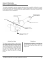
1
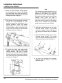
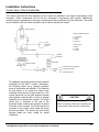
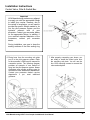
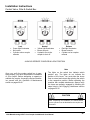
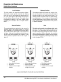
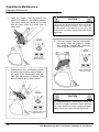
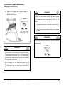
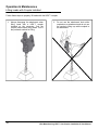
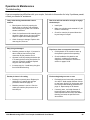
HDX™ Cast Coupler Installation & User Manual © 2013 HOA Manufacturing Inc. Eugene, OR USA. All rights reserved. Any use of the editorial or pictorial content of this publication is strictly prohibited without express written permission from HOA Manufacturing Inc. Printed in the USA (02/13). DCN HDX-IUM-01-20130216 TABLE OF CONTENTS INTRODUCTION Welcome & Contact Information ....................................................... 1 Important Notes & Warranty Information .......................................... 2 GENERAL INFORMATION Safety Messages & Recommendations ............................................ 3-4 Part Identification Charts ................................................................... 5-9 Hydraulic & Electrical Specifications ................................................. 10 HDX™ Coupler Familiarization ......................................................... 11-12 Recommended Welding Procedures ................................................ 13 INSTALLATION INSTRUCTIONS Installation Preparation ..................................................................... 14-15 Removing Attachment ....................................................................... 16 Connecting Coupler to Excavator Arm.............................................. 17 Installing Hose Brackets ................................................................... 18-19 Hydraulic Hose Assembly ................................................................. 20 Hydraulic Hose Routing .................................................................... 21-23 Control Valve, Filter & Switch Box .................................................... 24-28 OPERATION & MAINTENANCE Warnings & Precautions ................................................................... 29-30 Switch Box Overview ........................................................................ 31 Engaging Attachment ........................................................................ 32-35 Disengaging Attachment ................................................................... 36 Lifting Loads with Coupler Installed .................................................. 37 Maintenance Procedures .................................................................. 38-39 Troubleshooting ................................................................................ 40 HOA Manufacturing HDX™ Cast Coupler Installation & User Manual i Congratulations on your purchase of the HDX™ Cast Coupler. The HDX™ coupler is a high quality, well-engineered product that will provide you with many years of excellent service. The HDX™ coupler will deliver enhanced productivity of your excavator. This coupler brings you the design, quality and workmanship you expect from a HOA Manufacturing product. The advantages of the HDX™ coupler become apparent when a bucket or attachment change is necessary. These advantages include: A locking mechanism with a locking lever that engages under and around the attachment pin. A positive locking system, which pushes against the rear machine pin and away from the front pin, keeps the coupler tight at all times. A check valve that helps to prevent the possibility of an accidental release of the attachment. A lifting eye, which allows you to operate the machine as a lifting device without the attachment, provides increased lifting power without bucket interference. A redundant locking spring that maintains positive pressure on the front lever. The HDX™ coupler operates on the excavator’s low-pressure pilot system rather than the main high-pressure system. Engaging an attachment is easier and safer using the lowpressure pilot system. The attachment can remain on the ground and does not have to be curled in to take the machine over relief. The HDX™ coupler is designed to allow the operator to switch the attachments on a hydraulic excavator in a minimal amount of time. The HDX™ coupler’s full potential will depend upon proper installation, operation, and maintenance of the coupler and its systems. All users should read and understand this manual and any accompanying materials thoroughly prior to installing, operating, or maintaining your HDX™ coupler. Pay particular attention to your personal safety and remember to follow all applicable standard safety precautions. If you have any questions or concerns, contact your authorized HOA Manufacturing dealer. Thank you for purchasing our product. We are confident you will be pleased with its performance. Mailing Address Physical Address HOA Manufacturing Inc. PO Box 5134 Eugene, OR 97405 HOA Manufacturing Inc. 86360 Franklin Blvd C12 & 13 Eugene, OR 97405 Phone: 503.348.5761 1 HOA Manufacturing HDX™ Cast Coupler Installation & User Manual IMPORTANT NOTES HOA Manufacturing builds hydraulic couplers to OEM attachment specifications. Our coupler is designed to work only with attachments built to OEM attachment dimensions. The critical dimensions are the pin-center to pin-center, stick width, and pin diameter dimensions. One should properly ensure the attachments are built to these specifications before attempting to operate the coupler. Additionally, one may encounter some attachments that have structural interferences preventing the coupler from engaging the attachment. Any interference issues should be resolved before operating the coupler. HOA Manufacturing assumes no responsibility or liability for attachments not built to OEM specifications and/or that have structural interference problems. Any costs incurred to modify attachments that do not conform to OEM specifications and/or have structural interferences are solely the responsibility of the end user. HOA MANUFACTURING WARRANTY POLICY AND PROCEDURES FOR COUPLERS HOA Manufacturing warrants all couplers against defect in material and workmanship for a period of one year or 1000 hours from the date of install, whichever comes first. All warranty claims require submission of a PDI showing the original install date, as well as machine hours at time of defect. This warranty does not apply to any coupler that has been subjected to misapplication and/or abuse, or modified in any way without written authorization from HOA Manufacturing. This warranty covers only new products manufactured by HOA Manufacturing. Products manufactured by others are covered only by the warranties extended to HOA Manufacturing by its suppliers. Warranty claims must be made to HOA Manufacturing in advance of any repairs by submitting a Warranty Claim Number and Warranty Claim Form, which can be obtained by contacting HOA Manufacturing. Warranty claims made without a Warranty Claim Number will be rejected. Any product returned to HOA Manufacturing for inspection or repair must be returned with freight charges prepaid. If HOA Manufacturing authorizes repairs be made by an outside source, HOA Manufacturing reserves the right to determine and approve the time and rate charged for repairs. Repairs completed by an outside source will be subject to warranty one time only. Subsequent failure of repairs by an outside source is non-warrantable. HOA Manufacturing shall not be liable for downtime by the customer, mileage costs, damaged equipment, or loss of productivity incurred by the dealer or customer. All products are wearable and expendable, and as such, HOA Manufacturing assumes no responsibility for normal wear. It is the responsibility of the customer to follow normal maintenance and operating procedures, including, but not limited to, daily inspection for routine hairline cracks. Any cracks should be repaired to HOA Manufacturing specification before further damage occurs. HOA Manufacturing specifically disclaims any and all warranties, expressed or implied, including, but not limited to, any implied warranties of merchantability and fitness for any particular purpose with respect to HOA Manufacturing products. HOA Manufacturing HDX™ Cast Coupler Installation & User Manual 2 General Information Safety Messages & Recommendations To guard against death or injury, basic safety precautions should be observed before attempting to install, operate, or maintain your HDX™ coupler. This is the safety alert symbol. It is used to alert you of potential injury hazards. Observe all safety messages that follow this symbol. Safety messages in this manual are classified as follows: DANGER Indicates an imminently hazardous situation that may result in death or serious injury. WARNING Indicates a potentially hazardous situation that may result in death or serious injury. CAUTION Indicates a potentially hazardous situation that may result in minor or moderate injury and/or damage to the coupler or machine. Recommendations (Before You Begin) Read this manual thoroughly before attempting to install, operate, or maintain your HDX™ coupler. Before installing, unpack the coupler and Coupler Installation Kit. Inspect the shipper’s bill of lading and the Coupler Installation Kit component list on pages 7-9, to ensure you received all items. If items are missing, contact your dealer. Familiarize yourself with the coupler and Coupler Installation Kit components before installing, operating, or maintaining your HDX™ coupler (see pages 5-12). Sort your Coupler Installation Kit and group components together by component type. Be sure to group bolts with their respective washers. Inspect all items for damage due to transit or handling. If any items are damaged contact your dealer. Verify the coupler machine number on the Serial Number ID Tag (Fig. 3-1) matches the machine you are attempting to install the coupler on. Fig. 3-1 (Coupler Serial Number ID Tag) 3 HOA Manufacturing HDX™ Cast Coupler Installation & User Manual General Information Safety Messages & Recommendations Other Recommendations Install a Safe Operation decal on cab inside Do not force any parts during assembly. If the parts are properly aligned, the pins will go in easily and the fittings will screw into the valves without undue force. right hand window near switch. Always wear protective equipment during installation, inspection, and maintenance procedures. Avoid oil spills. Ensure you have an ample supply of rags and absorbent towels on hand for cleaning purposes. Dispose of all waste oils, fluids, lubricants, and other hazardous waste properly. Tighten all fittings securely and properly. Lubricate all pins. Always use the original machine pins, which came with the excavator, to attach the coupler to the excavator arm. Route Ensure all hoses, lines and fittings are clean, all hoses and wires in a neat and orderly manner. Secure the hoses and wires to other machine components. open, and clear before connecting them to the system. All hoses should have enough slack to move when powering attachment. the excavator arm or WARNING Read, understand, and follow all safety precautions and procedures found in the machine’s Operator Manual before attempting any operation, inspection, or maintenance of your machine, its attachments, and/or systems. HOA Manufacturing cannot anticipate every possible circumstance that might become a potential hazard. The warnings in this document and on the product are therefore not all inclusive. If a tool, procedure, work method, or operating technique not specifically recommended by HOA Manufacturing is used, you must make certain for yourself it is safe for you and others. You should also ensure the product will not be damaged or made unsafe by the operation, lubrication, maintenance and/or repair procedures you choose. DANGER Failure to comply with information in this HOA Manufacturing HDX™ Cast Coupler User Manual may result in injury, death, damage to property, and/or damage to the coupler. Ensure all personnel have read and understand the information in this manual before attempting to install, maintain, and/or operate the HDX™ coupler. HOA Manufacturing HDX™ Cast Coupler Installation & User Manual 4 General Information Part Identification Charts This section provides diagrams for identification of the excavator, the coupler, and the Coupler Installation Kit. These charts will also familiarize you with the terminology used in this manual. Chart 1 – Excavator Parts Chart 2 – Coupler/Attachment Parts 5 HOA Manufacturing HDX™ Cast Coupler Installation & User Manual General Information Part Identification Charts Chart 3 – HDX™ Coupler Parts (with Yoke) Chart 4 – HDX™ Coupler Pin Diameters The HDX™ coupler is designed to pick up multiple pin diameters. Refer to this chart for the appropriate pin diameter to match your HDX™ coupler. HDX™ Coupler Model Pin Diameter S120 60-65-70 mm S200 70-80 mm S250 80-90 mm S350 90-100 mm S450 100-110 mm HOA Manufacturing HDX™ Cast Coupler Installation & User Manual 6 General Information Part Identification Charts Chart 5 – Coupler Installation Kit Component List Filter Components Part Number #6N-3 #6N-412 Drawing Reference Filter Head 1753144 1 1 A Filter Element 20101 1 1 B 2” x 2” x 1/4” Angle Bracket MB-F 1 1 C 1/4” x 20” x 3/4” Hex Head Bolts with Washers 1/4 x 20 x 3/4 2 2 D #6N-3 #6N-412 Drawing Reference E Switch Box Components Part Number Buss 10 Amp Fuse FUSE10 1 1 3-Light Switch Box Assembly CCBX1020799-3 1 1 F #8 x 1/2” Mounting Screws 8 x 1/2MS 3 3 G Part Number #6N-3 #6N-412 Drawing Reference Hydraulic Control Valve (24V Vickers) DG4V3S2CMU1H560 1 1 H Mounting Sub Plate AD03SP-S6S 1 1 I 1/4” x 20” x 3/4” Sub Plate Mounting Bolts 1/4 x 20 x 3/4 SMB 2 2 J 1025 Mounting Screws BK-D03 4 4 K Control Valve Wiring Harness HARNDIQD 1 1 L Control Valve Mounting Bracket MB-V 1 1 M #6N-3 #6N-412 Drawing Reference 18 18 N Control Valve Components Fittings & Hoses Part Number #6 Reusable Female Hose Ends (Swivel) BL06-06NJ #6 O-Ring x #6 JIC Male (90 Degree) 849FSO06X06 5 5 O #8 O-Ring x #6 JIC Male 848FSO06X08 2 2 P #6 JIC Male x #6 JIC Male (Straight Bulkhead Fitting) 2700-06-06 2 2 Q #6 JIC Male x #6 JIC Male (45 Degree Bulkhead Fitting) 2702-06-06 2 2 R Nut for Bulkhead Fittings 711BHSF06 4 4 S #6 O-Ring x #6 JIC Male 6400-06-06 1 1 T Upper & Lower Bulkhead Fittings Bracket #6MB 2 2 U #6 2500 psi Single Braid Hydraulic Hose HFS06 125’ 150’ V Protective Hose Sleeve NHS114 20 20 W Wire Ties n/a 20 20 X Tubular Hose Retainer Bracket n/a 1 1 Y IMPORTANT HOA Manufacturing makes every attempt to supply you with the appropriate fittings to install your coupler. However, due to the variety of excavators, you will need to provide the specific fittings needed to tie into the pilot pressure system and the hydraulic reservoir tank of your excavator. Contact your excavator dealer for the appropriate fittings. In addition, if your machine requires adaptation of connectors, contact your excavator dealer. 7 HOA Manufacturing HDX™ Cast Coupler Installation & User Manual General Information Part Identification Charts The Coupler Installation Kit component drawings are not to scale and are for representation purposes only. B A Filter Head C 2” x 2” x 1/4” Angle Bracket Filter Element E D 1/4” x 20” x 3/4” Hex Head Bolts w/ Washers G F Buss 10 Amp Fuse 3-Light Switch Box Assembly H #8 x 1/2” x Mounting Screws Hydraulic Control Valve (24V Vickers) Mounting Sub Plate K 1025 Mounting Screws J I 1/4” x 20” x 3/4” Sub Plate Mounting Screws M L Control Valve Wiring Harness HOA Manufacturing HDX™ Cast Coupler Installation & User Manual Control Valve Mounting Bracket 8 General Information Part Identification Charts The Coupler Installation Kit component drawings are not to scale and are for representation purposes only. N Q R #6 JIC Male x #6 JIC Male (45 Degree Bulkhead Fitting) U #8 O-Ring x #6 JIC Male S #6 O-Ring x #6 JIC Male W #6 2500 psi Single Braid Hydraulic Hose X Protective Hose Sleeve Y Wire Ties 9 T Nut for Bulkhead Fittings V Upper & Lower Bulkhead Fittings Brackets P #6 O-Ring x #6 JIC Male (90 Degree) #6 Reusable Female Hose Ends (Swivel) #6 JIC Male x #6 JIC Male (Straight Bulkhead Fitting) O Tubular Hose Retainer Bracket HOA Manufacturing HDX™ Cast Coupler Installation & User Manual General Information Hydraulic & Electrical Specifications This table provides the specifications for the hydraulic and electrical components of the Coupler Installation Kit: Hydraulic Filter Unit Part Number Purolator 20101 Max Pressure 200 psi (13.8 bar) Flow Rating 32 gpm (121L/min) Temperature Range -45°F to 225°F (-43°C to 107°C) Filter Cross Reference (other brands) Parker #921999, Baldwin #BT839-10 and Stauff #SF6620 Switch Box Assembly Voltage Rating 24 VDC Alarm Decibel Rating 72 dBA Wiring Harness T4-2 SJT0W (TPE) 105°C FT2 water resistant Hydraulic Control Valve Part Number Vickers DG4V3S2CMU1H560 Power Rating 30W @ 24 VDC Fatigue Pressure 5000 psi (350 bar) System Pressure Excavator pilot pressure control system (Not to exceed 1000 psi) Hydraulic Hose #6 Single Braid Hose Eastman HFS06, 2500 psi (or equivalent) #4 Single Braid Hose Eastman E7-04, 2750 psi (or equivalent) CAUTION Only use parts recommended by HOA Manufacturing (or parts meeting the specifications above). Failure to use parts recommended by HOA Manufacturing may result in damage to the coupler and/or machine. HOA Manufacturing HDX™ Cast Coupler Installation & User Manual 10 General Information HDX™ Coupler Familiarization Your HDX™ coupler is built with a low profile design. It is constructed from high strength steel casting. It is built to accept OEM attachments, but is flexible enough to accept variances from these dimensions. Review the following to familiarize yourself with the coupler components. Frame is one piece cast steel with no structural welds, for long life. ( 1.5 times stronger than T1) OEM Boss Design Lifting Eye Springs Front Lever Multi-Pin Diameter Yoke Locking Rear Lever Multi-Pin Diameter Cylinder (see page 12) C-Casting Lifting Eye Front Lever The cast lifting eye on your coupler is durable and designed to handle the machine’s lifting capacity. The excavator gains additional lifting capacity in both weight and height when the coupler is used to lift the load without the attachment. The closed lifting eye should not be cut open or altered. An approved lifting shackle is recommended for attaching cables or other safety hoisting products. The HDX™ coupler features a cast front lever. The geometry of the front lever, along with the configuration and alignment of the other coupler components, hold the front lever in the closed position without the assistance of the hydraulic cylinder. Locking Rear Lever The cast rear locking lever slides under the attachment link pin in the rear mounting area of the coupler. The sliding mechanism is designed to minimize the chance of jamming. When the pin is seated properly in the lever, pressure from the hydraulic cylinder locks the attachment link pin between the coupler frame and the sliding lever. Because the locking system pushes away from the front pin, the coupler remains tight, even as it begins to wear. 11 Springs Constant pressure is maintained on the front lever by two tension springs. These springs assist the hydraulic cylinder by keeping the front lever closed and secured. C-Casting The C-casting fits two different pin diameters and is FEA contoured for low stress. HOA Manufacturing HDX™ Cast Coupler Installation & User Manual General Information HDX™ Coupler Familiarization The cylinder is designed for maximum extension, giving more bucket compatibility. Additionally, it can be used with yoke to give ultra long stroke capabilities. The double acting cylinder on the coupler is plumbed for an external check valve. This feature locks the hydraulic pressure in the cylinder to prevent it from backing away from the pin engagement. Hardened ball and socket (spherical) self aligns and requires no lubrication Hydraulic ports are positional for easy access Bleed Screw Oversize solid chrome rod Cylinder check valve is a cartridge type and separately serviceable Shafts are machined from a solid block of steel, eliminating crack prone welds Cylinder Check Valve Bleed Screw The hydraulic cylinder features an external check valve in the terminal block, on top of the cylinder. This provides easy access and servicing of this unit. Should a hose break, the check valve will maintain constant pressure on the attachment link pin. Once the attachment is engaged, the locking lever can only be retracted by applying positive pressure to the retract port. This is done by placing the control box switch to the release position. The bleed screw is installed so you can bleed any air that may be in the cylinder. This must be done after the install, any time a hose is removed, as well as, any time after the machine sits for any length of time. HOA Manufacturing HDX™ Cast Coupler Installation & User Manual 12 General Information Recommended Welding Procedures HOA Manufacturing high strength, low alloy steels require greater than normal precautions when welding. Follow this list of welding recommendations and procedures when installing and maintaining your coupler. When welding, always use proper welding protection and work in a well ventilated area. Use an electrode or wire with a 70,000 lb tensile strength or higher. The cast frame can accommodate the use of 70,000-110,000 lb tensile strength. The higher the tensile strength, the stronger the weld. However, the higher tensile strength is more difficult to weld. Preference should be given to weld quality, rather than tensile strength. Place the welding ground cable within three feet (one meter) of the area to be welded. Ensure all areas to be welded are clean, free of moisture, and properly aligned. Remove paint from any surface to be heated or welded. Painted surfaces give off unhealthy gases when heated. Use a mask and proper skin protection when removing paint from any surface. If you remove the paint by sanding the objects, take care not to breathe the generated dust. Protect yourself by wearing a mask. If you remove the paint by using chemical compounds, completely clean the surface using plenty of soap and water. Chemicals generate unhealthy gases when heated. Preheat parts to be welded to a temperature of 300ºF to 400ºF (150ºC to 200ºC). Run stringer passes; minimize heat input and welding time by using short stringer beads to remove stress. Cool slowly after welding. If temperature is 50ºF (10ºC) or below, wrap with an insulation blanket. A localized post weld heat treatment with a Rosebud torch should include at least two inches minimum of the adjacent base metal and the weld. This heat treatment should raise the temperature of the heated area to 400ºF to 500ºF (200ºC to 260ºC). Control of this step is critical to avoid embrittling the steel. Have a fire extinguisher and first aid kit ready for emergencies. Know how to operate the fire extinguisher and know where the first aid is located in case of an emergency. 13 Make sure to disconnect the batteries. Failure to do so could result in extensive machine damage to the electronic system. HOA Manufacturing HDX™ Cast Coupler Installation & User Manual Installation Instructions Installation Preparation This section will guide you through the necessary steps to install your HDX™ coupler. Review the information provided in the General Information section (pages 3-13) before attempting to install your coupler. Pay close attention to all safety message in this manual. The couplers installation will require you to do the following basic steps: 1. Connect the coupler to the end of the excavator’s arm. 2. Route the hoses from the coupler up the excavator arm and boom, then down to the engine compartment that houses the low-pressure pilot system. 3. Install the control valve and filter in the engine compartment. This will provide easy access to the low-pressure pilot system, as well as, protection from the elements. 4. Mount the 3-light switch box in the cab of the excavator. Helpful Hints Before Beginning Installation Fully read the Installation Instructions section (pages 14-28) before beginning the installation. Determine where you will need to mount the control valve and filter (these components are mounted in the main engine compartment near the excavator’s pilot pressure system). Determine where, in the excavator cab, you will need to mount the switch box. Make sure you have the proper fittings needed to tie into the pilot pressure system and the hydraulic return system. These fittings are not supplied with the Coupler Installation Kit. Check to determine if the tubular hose bracket can be welded to the excavator’s H-link. Determine the best route for running the hoses on the excavator. The hoses should not interfere with other excavator components. DANGER Failure to comply with information in this HOA Manufacturing HDX™ Cast Coupler User Manual may result in injury, death, damage to property and/or damage to the coupler. Ensure all personnel have read and understand the information in this manual before attempting to install, maintain, and/or operate the HDX™ coupler. HOA Manufacturing HDX™ Cast Coupler Installation & User Manual 14 Installation Instructions Installation Preparation Follow this reference list for necessary preparation steps before beginning the coupler installation. Place the excavator, coupler, and all tools and supplies needed in an open, unencumbered work area. Make sure the machine and coupler are on flat, secure ground. Inspect the coupler and all Coupler Installation Kit components for signs of damage. Ensure the Coupler Installation Kit is complete and none of the components are damaged. If any components are damaged or missing, notify your dealer. Familiarize yourself with the components of the coupler (see Chart #3 on page 6) and the Coupler Installation Kit (see Chart #5 on pages 7-9). The coupler ships with a set of attachment pins. Remove these attachment pins from the coupler. They are not case-hardened pins and are designed to be used in the ears of the bucket or attachment. You are now ready to begin the coupler installation. CAUTION Never allow a hydraulic line or component to become contaminated. Contamination in the hydraulic system can cause severe system damage. Contact your excavator dealer to obtain the proper caps and plugs used on your model excavator. Do not connect the HDX™ coupler to hydraulic pressures exceeding 1000 psi. The HDX™ coupler is designed to operate off of the excavator’s low-pressure pilot system. Only connect the coupler to the excavator’s low-pressure pilot system. WARNING Avoid oil spills. Use containers, rags, and/or absorbent towels to contain any oil leakage. Dispose of all waste oil, fluids, lubricants, and other hazardous waste properly. Always use the proper safety protection such as: hard hats, work gloves, safety shoes, and safety glasses when operating, maintaining, or installing this equipment. HDX™ couplers are designed to be used only with a HOA Manufacturing Coupler Installation Kit. Installing a coupler with anything other than components from a HOA Manufacturing Coupler Installation Kit results in an unauthorized modification to the coupler. Any unauthorized modifications may impair function, affect performance, and affect the life of the coupler, the excavator and/or the attachment. Unauthorized modifications may result in injury or death. HOA Manufacturing disclaims any liability and responsibility resulting from unauthorized modification. Unauthorized modification voids all warranties. 15 HOA Manufacturing HDX™ Cast Coupler Installation & User Manual Installation Instructions Removing Attachment The following steps are necessary to remove an existing attachment from the excavator before beginning the coupler installation. 1. Make sure the throttle control is in the low idle position. Start the engine. 4. Remove the retaining bolts from the pins. 2. Unlock the safety lever. 5. Remove both the stick and link pin from the arm-to-bucket connection. 3. Operate the attachment controls on the excavator to position the attachment securely on firm, level ground. 6. Operate the excavator controls to remove the excavator arm from between the ears of the attachment. 7. Rest the excavator arm securely on firm, level ground. HOA Manufacturing HDX™ Cast Coupler Installation & User Manual 16 Installation Instructions Connecting Coupler to Excavator Arm The following steps are necessary to connect your coupler unit to the excavator’s arm. 1. Ensure the coupler is resting securely on firm, level ground and pins are not in the coupler. CAUTION Make sure you use the original machine pins from your excavator to connect the coupler to the arm of the excavator. Do not use the attachment pins, which were shipped with the coupler, to connect the coupler to the arm of the excavator. 2. If the attachment pins, which were shipped with the coupler, are still in the coupler, remove the pins. You cannot use these attachment pins to connect the coupler to the excavator arm. You must use the pins that came with your excavator. The attachment pins, which were shipped with the coupler, are only used in the ears of the bucket or attachment. 3. If your machine requires O-rings, roll the Orings onto the coupler bosses. 4. You are now ready to connect the coupler to the excavator arm. With the throttle control in the low idle position, slowly operate the excavator controls to align the stick pin hole to the stick-side of the coupler. Insert the stick machine pin. Use the original stick machine pin, which came with the excavator, to connect the coupler to the stick. Use a rubber mallet to drive the pin into place. 17 5. Slowly operate the bucket cylinder on the excavator to align the excavator’s pivot link hole with the link-side of the coupler. Insert the link machine pin. Use the original link machine pin, which came with the excavator, to connect the coupler to the pivot link. Use a rubber mallet to drive the pin into place. A pry bar may be necessary to help adjust the pivot link in order to ease installation. 6. Secure the stick and link pins in place by installing their respective retaining bolts and nuts. 7. Your coupler is now connected to the excavator arm. HOA Manufacturing HDX™ Cast Coupler Installation & User Manual Installation Instructions Installing Hose Brackets The Coupler Installation Kit includes several brackets to help you neatly route your hoses. The lower bulkhead fittings bracket mounts on the excavator arm, near the arm idler connection point. This bracket helps route the hoses from the end of the excavator arm to the coupler cylinder. The upper bulkhead fittings bracket mounts on the top portion of the excavator arm, underneath the excavator’s bucket cylinder. This bracket helps route the hoses up the arm of the excavator. The tubular hose retainer bracket mounts on the inside of the excavator’s bucket linkage. The tubular hose retainer bracket helps guide the hoses from the lower bulkhead fittings bracket to the coupler’s cylinder. The following steps will guide you through the process of installing these brackets to the excavator. 1. With the excavator sitting on firm, level ground, rest the excavator arm in an extended position. 2. Place the throttle control in the low idle position and turn the ignition key off. 6. Disconnect the negative cable from the battery terminal. 7. Attach the lower bulkhead fittings bracket to the excavator arm. Remove the fittings from the bracket and weld the bracket to the excavator arm using the recommended welding procedures on page 13. 8. The location of the lower bulkhead fittings bracket will vary depending on your specific excavator/arm combination. For a general guideline, install the bracket 9” from the center of the excavator arm’s idler pin. The angle of the bracket should be approximately at the 9” point. Weld the brackets using the recommended welding procedures on page 13. 3. Place the safety lever in the locked position before leaving the cab. 4. Secure a Lock Out tag on the operator’s console to inform users the machine is inoperable. See your excavator dealer for the appropriate Lock Out tag. 5. Release the hydraulic tank pressure by operating the release valve on the hydraulic tank. HOA Manufacturing HDX™ Cast Coupler Installation & User Manual 18 Installation Instructions Installing Hose Brackets Note 9. Attach the upper bulkhead fittings bracket to the excavator arm. Remove the fittings from the bracket, then weld the bracket to the excavator arm using the recommended welding procedures on page 13. 10. The location of the upper bulkhead fittings bracket will vary depending on your specific excavator/arm combination. For a general guideline, install the bracket approximately 20” to 24” from the center of the bucket cylinder connection pin. Weld the bracket using the recommended welding procedures on page 13. The tubular hose retainer bracket may not work on all excavator H-links. The main objective for the bracket is to guide the hoses from the lower bulkhead fittings to the coupler cylinder and to prevent hose chaffing. Some H-links are made of materials not suitable for welding. Other Hlinks may allow the hoses to slip through them. Find a method that will properly guide the hoses and prevent chaffing. 12. Install the bulkhead fittings into the upper bulkhead fittings bracket. This bracket uses the 45 degree bulkhead fittings and the fittings are secured by the bulkhead nut. 13. Install the bulkhead fittings into the lower bulkhead fittings bracket. This bracket uses the straight bulkhead fittings and the fittings are secured by the bulkhead nut. 11. To guide the hoses and help prevent chaffing, mount the optional tubular hose retainer bracket. This piece of tubing mounts to the inside of the bucket H-link. Position the tubing in the center of the link and weld using the recommended welding procedures on page 13. 19 14. You have now mounted the necessary brackets and are ready to route the hydraulic hoses. HOA Manufacturing HDX™ Cast Coupler Installation & User Manual Installation Instructions Hydraulic Hose Assembly This section details the process of making the hydraulic hoses required for the coupler installation. HOA Manufacturing makes every attempt to provide adequate hose length for your coupler installation. However, depending on your excavator, you may find you need extra hose. See the hose specifications listed on the Coupler Installation Kit component list on page 7, to determine if you will need extra hose. A. Place socket in a vise. D. Hold hose with the vise. B. Cut hose to length and dip into heavy oil. E. Dip hose end of nipple into heavy oil. C. Screw hose counter-clockwise into the socket until it bottoms out, then back hose out 1/2 turn. F. Using a wrench, screw nipple assembly completely into socket. HOA Manufacturing HDX™ Cast Coupler Installation & User Manual 20 Installation Instructions Hydraulic Hose Routing The following steps are necessary to route the hydraulic hoses for your coupler installation. The hoses must be routed from the engine compartment (where they will tie into the pilot pressure system) to the coupler. CAUTION The exact manner in which you need to route your hoses will vary depending on the specifics of your excavator. Use the following steps as a guideline only. Always route all hoses in the manner that will prevent interfering with other lines and equipment. Be sure to secure all hoses to the excavator. 3. Route the hoses through the excavator’s linkage, as shown in the diagram below. Make sure the hose has enough slack to move with the excavator linkage. Allow for some flexibility. Protect all moving hoses with the supplied hose guard sleeves. Note: Step 4 offers a procedure for determining the proper length of hose. 1. Before connecting any hoses, be sure the hoses have been flushed completely with clean hydraulic fluid to prevent contamination. 2. Install the 90 degree #6 O-ring x #6 JIC male fittings into the extend and retract ports on the cylinder. 21 HOA Manufacturing HDX™ Cast Coupler Installation & User Manual Installation Instructions Hydraulic Hose Routing 4. In order to determine the proper hose length, cut two pieces of hose allowing plenty of extra hose. Install the hose fittings on one end only. Connect the hoses to the coupler cylinder. Route the hoses through the excavator linkage. Slowly operate the excavator controls so the coupler is curled in completely. Pull the hoses tight to the lower bulkhead fittings bracket. Release tension on the hoses allowing a small amount of slack. Mark the hoses, cut and then assemble the hose fittings on the coupler. 5. After installing the lower hose from the coupler to the lower bulkhead fittings bracket, begin routing the remaining hose sections. Measure and install the hose between the lower bulkhead fittings bracket and the upper bulkhead fittings bracket. Remember to route the hoses in a manner that will not interfere with other lines and equipment. WARNING Be sure to eliminate any twisting of the hoses before tightening the connections. Do not put hands into moving excavator linkage. HOA Manufacturing HDX™ Cast Coupler Installation & User Manual 22 Installation Instructions Hydraulic Hose Routing 6. Next, you will need to route the hoses from the upper bulkhead fittings bracket back to the engine compartment. Install a hose fitting on one end, then route the hose to the excavator’s bucket cylinder and down the boom. Route the hoses in a manner that will prevent interference with other lines or equipment. Secure the hoses to the machine using the plastic tie wraps supplied in the Coupler Installation Kit. Repeat this procedure for both sides. 23 7. Carry both of your hoses all the way into the engine compartment that houses the pilot pressure system. Make sure you have plenty of slack where the line ends in the engine compartment. You will tie these two hoses into the control valve. See instructions on the next page. HOA Manufacturing HDX™ Cast Coupler Installation & User Manual Installation Instructions Control Valve, Filter & Switch Box The control valve and the filter assembly for the coupler are installed in the engine compartment of the excavator. These components will tie into the excavator's low-pressure pilot system. Additionally, mounting these components in the engine compartment offers protection from the elements. The switch box is installed in the cab of the excavator and is used to operate the coupler. Coupler Cylinder R Mounting Subplate Legend E Extend Retract P - Pilot Pump A - Hose A T - Tank B - Hose B Pilot Pressure Pump P Wiring Legend B - Black W - White G - Green B A Mounting Sub Plate T Hydraulic Reservoir Control Valve Switch Box Wiring Harness Release Lock B W G 3 Wire Lead This diagram shows the electrical and hydraulic schematic for the HDX™ coupler. Remember, the following steps are a general guideline, since all excavators are different. The objective for this section is to mount the control valve (solenoid valve) and the 3-light switch box. The control valve ties into the pilot pressure system and hydraulic reservoir tank in order to provide hydraulic flow to operate the coupler. The 3-light switch box is mounted in the cab of the excavator and is used by the operator to control the action of the coupler. The 3-light switch box connects to the control valve using the wiring harness provided. The switch box and wiring harness leads are color coded for easier installation. 2 Wire Lead W To Excavator 24 VDC System 10 Amp Fuse Linked B To System Ground CAUTION Before connecting hoses, flush completely with clean hydraulic fluid to prevent contamination. HOA Manufacturing HDX™ Cast Coupler Installation & User Manual 24 Installation Instructions Control Valve, Filter & Switch Box 1. In the engine compartment, which houses the low-pressure pilot system of the excavator, mount the control valve mounting bracket. You should weld the bracket in a place that does not interfere with other excavator components, but allows easy access to the pilot pressure system. When mounting the bracket, follow the recommended welding procedures on page 13. 3. Install three 90 degree #6 O-ring x #6 JIC male fittings and one straight #6 O-ring x #6 JIC male into the mounting sub plate. CAUTION Do not connect the HDX™ coupler to hydraulic pressures exceeding 1000 psi. The HDX™ coupler is designed to operate off of the excavator’s lowpressure system. Only connect the coupler to the excavator’s pilot system. 2. Mount the mounting sub plate to the mounting bracket using the supplied sub plate mounting screws. The mounting sub plate ports are marked as follows: T = Tank P = Pilot Pump A = Hose B = Hose 4. Connect the hoses to the mounting sub plate. The two hoses that run from the coupler cylinder into the mounting sub plate connect ports A & B. Run a hose from the mounting sub plate port P to the pilot pressure pump. Route a hose from the mounting sub plate port T to the hydraulic reservoir tank. 5. Mount the filter assembly in an area that provides easy access to the hydraulic reservoir tank, but does not interfere with other equipment in the engine compartment. The filter is mounted in-line, between the mounting sub plate and the tank. 25 HOA Manufacturing HDX™ Cast Coupler Installation & User Manual Installation Instructions Control Valve, Filter & Switch Box Important HOA Manufacturing makes every attempt to supply you with the appropriate fittings to install your coupler. However, due to the variety of excavators, you will need to provide the specific fittings needed to tie into the pilot pressure system and the hydraulic reservoir tank of your excavator. Contact your excavator dealer for the appropriate fittings. In addition, if your machine requires adaptation of the connectors, contact your excavator dealer. During installation, use care to keep the sealing surfaces of the filter sealing ring 6. Route hose from the mounting sub plate port P to the pilot pressure system. Refer to the excavator’s OEM service manual for connection points. The following diagram provides an example of one method of tying into the pilot pressure system. Newer excavators may provide auxiliary ports for connections from aftermarket attachments. Contact your excavator dealer’s service department if you need additional guidance. 7. After properly connecting your hoses, you are ready to install the control valve onto the mounting sub plate. You will use the four 1025 mounting screws to connect the valve and sub plate. HOA Manufacturing HDX™ Cast Coupler Installation & User Manual 26 Installation Instructions Control Valve, Filter & Switch Box 8. Install the wiring harness onto the control valve. The harness is marked for the lockside and the release-side. The lock-side of the harness should be connected to the side of the control valve where the extend line comes into the sub plate. The releaseside of the harness should be connected to the side of the control valve where the retract line comes into the sub plate. The wiring harness has three color coded leads The black is the ground; white is release; and green is locked. 11. The second cable has two leads (black and white) and is approximately six feet long. Connect the white lead to the excavator’s 24VDC system. Link with the supplied buss 10 AMP fuse. Fused circuits on the excavator should be used where applicable. Connect the black lead to the system ground. Make all wiring connections in accordance with standard electrical practices. Refer to SAE J2030 Heavy Duty Electrical Connector Performance Standard. 12. After making all switchbox connections, test the installation of the coupler. With the machine power on and no attachment connected to the coupler, place the switch to the lock position. The green light on the switch box should illuminate and the coupler cylinder rod should extend. If the cylinder rod retracts, then your connections are installed in reverse. To rectify, reverse the wiring harness DIN connectors and retest the installation by repeating this step. If the switch box and coupler cylinder do not operate correctly, recheck the installation of all electrical and hydraulic components and ensure they are installed in accordance with the instructions in this manual. If the problem persists, contact your dealer. 9. Inside the excavator cab, mount the 3-light switch box in an easily accessible area that does not interfere with the operation of the excavator. 10. The switch box has two cables. The first cable has three leads (black, white and green) and is approximately 20 feet long. Route this cable back to the engine compartment containing the control valve. Connect the three leads of the switch box to the three leads on the control valve wiring harness. Match the color coded wires and connect them in accordance with standard electrical practices. Refer to SAE J2030 Heavy Duty Electrical Connector Performance Standard. 27 13. After completing the installation, the bleed screws on the cylinder must be bled before the coupler can be tested. DANGER Conduct tests away from all personnel. Remove any attachments prior to testing the switch box installation. HOA Manufacturing HDX™ Cast Coupler Installation & User Manual Installation Instructions Control Valve, Filter & Switch Box Lock Green light illuminates No buzzer Cylinder rod on coupler extends Neutral Yellow light illuminates Buzzer sounds Hydraulic flow to the coupler is shut off Release Red light illuminates Buzzer sounds Cylinder rod on coupler retracts ALWAYS OPERATE COUPLER IN LOCK POSITION Note Once you verify the coupler switch box is operating properly, you have completed the installation of your coupler. Before attempting to operate or maintain the coupler, thoroughly read and familiarize yourself with the Operation & Maintenance section on pages 29-40. The lights on the switch box indicate switch position only. The lights do not indicate the position of the levers. You must allow the levers time to extend and retract after placing the switch in the respective position. Before operating the machine with coupled attachments, always verify the levers are properly engaged by following the steps listed in the Engaging Attachment section on pages 32-35. CAUTION After completing the installation, the bleed screws on the cylinder must be bled before the coupler can be tested. HOA Manufacturing HDX™ Cast Coupler Installation & User Manual 28 Operation & Maintenance Warnings & Precautions This section provides warnings and precautions to take before operating and/or maintaining your HDX™ coupler. DANGER Failure to comply with information in this HOA Manufacturing HDX™ Cast Coupler User Manual may result in injury, death, damage to property, and/or damage to the coupler. Ensure all personnel have read and understand the information in this manual before attempting to install, maintain, and/or operate the HDX™ coupler. CAUTION The excavator’s effective reach, as well as, the attachment tip radius are increased with the HDX™ coupler installed. Keep in mind the attachment can come in contact with the boom, arm, and/or cab, depending on the coupler/attachment combination. The excavator’s attachment range of motion changes with the HDX™ coupler installed; specifically, the bucket dump angle and the bucket curl angle. The operator may experience slow or unexpected movement when operating with cold hydraulic oil. Likewise, damage to the hydraulic components can occur due to the cold oil. Make sure to warm up the hydraulic system before operating. Never allow a hydraulic line or component to become contaminated. This could cause severe system damage. Contact an authorized machine distributor to obtain proper caps and plugs to use on your machine. Do not connect the HDX™ coupler to hydraulic pressures over 1000 psi. The HDX™ coupler is designed to operate on the low-pressure pilot system. DANGER Improper operation and maintenance of this equipment may result in serious injury or death. Read the HOA Manufacturing HDX™ Cast Coupler User Manual thoroughly before operating and/or maintaining this equipment. Unauthorized modification to the coupler and/or any coupler components may impair function, affect performance, and affect the life of the coupler, the excavator, and/or the attachment. Unauthorized modification may impair the safety of personnel and may cause serious injury or death. HOA Manufacturing assumes no responsibility for any unauthorized modification to the coupler and/or coupler components. Unauthorized modification voids all warranties. Test connections away from all personnel. Never swing coupled attachments over workers’ heads. 29 HOA Manufacturing HDX™ Cast Coupler Installation & User Manual Operation & Maintenance Warnings & Precautions Review the information provided in the All excavator operators should familiarize General Information section (pages 3-13) before attempting to operate and maintain your coupler. themselves with all coupler/attachment combinations before attempting to operate the coupler. This includes, but is not limited to, practicing engaging and disengaging each attachment. Furthermore, when new attachments are added to the machine’s fleet, the operators should proceed with the same familiarization process before being used on the jobsite. Review the instructions and safety precautions thoroughly before attempting to operate or maintain the coupler. Inspect the coupler and all coupler components daily, before beginning operation. Perform any necessary repairs before operating the coupler. Ensure both springs and all spring pins are present prior to operating the coupler. Check for any obstruction inside the coupler frame and remove before using the coupler. Under normal conditions, all machine hydraulic circuits are under extreme pressure. Small (pinhole) leaks can be dangerous if hydraulic oil contacts skin or eyes. As part of daily maintenance, check for leaks. Always wear protective equipment when performing inspection and maintenance procedures. All coupler/attachment combinations should be checked for possible interference before using. Interference problems should be corrected before using the coupler. Ensure the coupler engages and disengages properly and easily. Only operate the coupler with the control box switch in the lock position. The green light indicator will illuminate when the switch is placed in the lock position. The buzzer alarm indicates a potential unlock condition in the coupler. Do not attempt to operate the attachment if this condition is present. Always verify visually the attachment is properly locked. Make sure the buzzer alarm functions properly at all times. Do not use the coupler as a prying tool or clamping device. Do not use the coupler without an attachment, except when used for lifting. Do not use the coupler if it is severely worn. Make sure to repair before resuming operation. WARNING Perform all connection tests before attempting to operate the coupler. Make sure the attachment is resting on the ground and properly supported before performing any work on the coupler. Avoid oil spills. Use containers, absorbent towels and/or rags, to contain oil leakage. Dispose of all waste oils, fluids, lubricants and other hazardous waste properly. During inspection and maintenance of your coupler, use safety protection such as: hard hats, face shields, work gloves, safety shoes, work clothes and safety glasses. Maintenance work should only be performed by experienced and qualified personnel. HOA Manufacturing HDX™ Cast Coupler Installation & User Manual 30 Operation & Maintenance Switch Box Overview Lock Position Release Position The lock position will extend the coupler cylinder. When the coupler cylinder extends, the locking lever will move to and engage the attachment link pin. The green light on the switch box will glow and the buzzer alarm will stop. The switch must be placed and remain in the lock position while operating the excavator with a coupled attachment. The release position will retract the coupler cylinder. In this position, the buzzer alarm will sound and the red light on the switch box will glow. The release position should be used only when changing attachments. If the coupler is disconnected from an attachment for any length of time, the selector switch may be returned to the lock position to silence the alarm. Neutral Position Note The neutral position is used only in the event of a hydraulic leak in the coupler system (i.e. coupler hose breakage). In this position, the buzzer alarm will sound and the yellow light on the switch box will glow. Under no circumstance should this position be used while operating the coupler. In the neutral position, hydraulic flow to the coupler is shut off. The lights on the switch box indicate switch position only. The lights do not indicate the position of the levers. You must allow the levers time to extend and retract after placing the switch in the respective position. Before operating the machine with coupled attachments, always verify the levers are properly engaged by following the steps listed in the on pages 32-35. Lock Green light illuminates No buzzer Cylinder rod on coupler extends Neutral Yellow light illuminates Buzzer sounds Hydraulic flow to the coupler is shut off Release Red light illuminates Buzzer sounds Cylinder rod on coupler retracts ALWAYS OPERATE COUPLER IN LOCK POSITION 31 HOA Manufacturing HDX™ Cast Coupler Installation & User Manual Operation & Maintenance Engaging Attachment The HDX™ coupler locks into place by engaging the front lever over and around the stick pin. The rear lever will then engage under and around the attachment’s link pin. This will lock the stick pin against the C-casting. This section details how to properly engage an attachment with the HDX™ coupler. The rear lever engages under and around the attachment’s link pin, causing the stick pin to lock into the c-casting. The front lever engages in front of the attachment’s stick pin to prevent accidental disengagement. DANGER Failure to properly engage an attachment may result in serious injury or death. The attachment may drop without warning if the coupler is not properly engaged with the attachment. Read this section carefully and perform the following steps each and every time you change attachments. 1. Engage attachments completely clear of all personnel. 2. Test connections away from all personnel. 3. Never swing coupled attachments over workers’ heads. HOA Manufacturing HDX™ Cast Coupler Installation & User Manual 32 Operation & Maintenance Engaging Attachment 1. Open the coupler lever by placing the control box switch in the release position. The buzzer alarm will sound and the red light will glow. Allow the levers time to retract fully. CAUTION The control box switch should still be in the release position while seating the coupler. The coupler must be fully seated on the attachment’s link pin for the locking lever to properly engage under and around the link pin. 3. Seat the coupler onto the attachment’s link pin by curling the coupler in toward the machine (extend the machine’s bucket cylinder as shown below). Release before engaging attachment 2. Keep in release while seating the coupler Operate boom, arm, and bucket cylinders to position the coupler at approximately a 45º angle on the attachment’s stick pin. Fully seat the coupler’s C-casting (front jaw) on the stick pin as shown below. CAUTION All coupler/attachment combinations should be checked for possible interference before operating the coupler. Ensure the coupler engages and disengages properly and easily with each attachment. Keep in release position while engaging attachment 33 HOA Manufacturing HDX™ Cast Coupler Installation & User Manual Operation & Maintenance Engaging Attachment 4. After fully seating the coupler, switch to the lock position to engage the link pin with the lock lever. DANGER Connection tests must be performed every time you engage an attachment. Failure to properly engage an attachment may result in serious injury or death. The attachment may drop without warning if the coupler is not properly engaged with the attachment. Switch to lock to engage link pin with lock lever Engage attachments completely clear of all personnel. Test connections away from all personnel. Never swing coupled attachments over workers’ heads. DANGER The control switch should always remain in the lock position while operating the excavator with coupled attachments. DANGER The rear lever is the locking device for the coupler. The purpose of the front lever is to act as a back up in case failure to the rear lever. You must ensure the rear lever along with the front lever is properly engaged before attempting to operate the excavator with a coupled attachment. After the front lever engages, allow time for the rear lever to engage. Do not assume the rear lever is engaged just because the front lever is engaged. You must allow the rear lever time to engage the attachment’s link pin. HOA Manufacturing HDX™ Cast Coupler Installation & User 34 Operation & Maintenance Engaging Attachment Connection tests must be performed each time you engage the attachment. 5. Connection Test One Test the connection to the attachment by completely curling the coupler inward. 7. Connection Test Three Test the coupler connection by trying to disengage the attachment from the coupler using the machine’s weight. Dig the attachment in the ground, lower the attachment against the ground and try to force the attachment off by lifting the excavator’s tracks off the ground. 6. Connection Test Two Test the connection by fully cycling the coupled attachment at least twice. 8. After performing all connection tests, you are ready to operate your machine with the coupled attachment. DANGER The switch must remain in the lock position when operating the excavator with coupled attachments. Never swing coupled attachments over workers’ heads. 35 HOA Manufacturing HDX™ Cast Coupler Installation & User Manual Operation & Maintenance Disengaging Attachment The following details the proper steps for disengaging from an attachment with the HDX™ coupler. 1. Place the attachment on secure, flat ground. Clear all personnel from the vicinity of the attachment. Switch the control box to the release position. The buzzer will sound and the red light will glow. 2. Unlatch the attachment link pin by curling the coupler out (retract the machine’s bucket cylinder) and simultaneously lift the boom to completely disengage the coupler from the attachment. Place the bucket on the ground and switch to the release position Keep in release while unlatching bucket DANGER CAUTION Never use the release position when a coupled attachment is off the ground. When disengaging from an attachment, turn the switch to the release position long enough to ensure the levers are completely open before curling the coupler out. Never swing coupled attachments over workers’ heads. Do not force the coupler off of the attachment. DANGER Always disengage personnel. HOA Manufacturing HDX™ Cast Coupler Installation & User Manual attachments away from 36 Operation & Maintenance Lifting Loads with Coupler Installed Follow these steps to properly lift loads with the HDX™ coupler. 1. 37 Always disengage the attachment when lifting loads with a HDX™ coupler installed on the excavator. Curl the coupler inward when lifting loads. This is the preferred method for lifting. 2. Do not use the attachment hook while coupled on an attachment and do not use the coupler’s lifting eye while coupled to an attachment. HOA Manufacturing HDX™ Cast Coupler Installation & User Manual Operation & Maintenance Maintenance Procedures You will need to maintain your HDX™ coupler on a regular basis and as needed. The maintenance procedures for this coupler include: Front C-Casting Buildup When play exists between the arm pin and the Ccasting, disengage the attachment and place the template at the arm pin C-casting, as shown below. Measure across the complete width of the arm pin location and mark the areas of the coupler that do not match the arm pin template. Preheat the C-casting area to 400ºF (205ºC). Weld across the complete width of the arm pin location, using the recommended welding procedures on page 13. Clean the access weld to match the profile of the arm pin template. After all welding is complete, grind smooth the outer diameter of the hook plates. When a template is not available proceed as follows to rebuild the C-casting: Allow pin to rest at the bottom of the C-casting. Wedge pin to the back of the C-casting. Mark at the top of the pin (approximately centerline of pin), where the weld buildup should begin. Weld three beds, side-by-side, through the entire width of the C-casting. Grind the weld smooth and check the pin fit. Repeat welding process until the desired pin fit is achieved. Weld using the recommended welding procedures on page 13. If the C-casting is severely worn, proceed as indicated above, but also weld on bottom side of the C-casting. Small Pin If pin bottoms out at the back of the C-casting, then the C-casting needs to be built up. Gaps between the template and coupler indicate worn areas. Those worn areas should be built up and then ground to fit the template. After buildup is complete, grind both sides smooth. HOA Manufacturing HDX™ Cast Coupler Installation & User Manual Large Pin If gap is more than 1/32”, then the C-casting needs to be built up. 38 Operation & Maintenance Maintenance Procedures Coupler Lubrication Filter Replacement Lubrication of this coupler is not recommended or required. Levers are designed to run without lubrication due to the hardness and self lubricating characteristics of the steel casting material. A hydraulic filter is provided for your HDX™ coupler. This filter should be replaced once a year or every 1000 machine hours, whichever comes first. Only use filters recommended by HOA Manufacturing. Specific information about your filter is listed on page 10 of this manual. Springs Coupler Repair Parts (Dealer Stock) For every ten couplers sold to customers, we recommend a dealer stock the following items. These are easily installed in the field and will reduce downtime. 39 1 cylinder 1 rear lever 1 yoke 1 front lever 1 set of springs 1 set of spring pins Inspect daily to make sure the springs are installed properly and are not damaged or missing. Replace any damaged or missing springs immediately. Both springs need to be replaced (as a set) annually, regardless of their condition. Only use springs supplied by HOA Manufacturing and designed for your HDX™ coupler. Installing any other springs void the warranty and may result in injury death, damage to property and/or damage to the HDX™ coupler. HOA Manufacturing HDX™ Cast Coupler Installation & User Manual Operation & Maintenance Troubleshooting If you are experiencing difficulties with your coupler, first refer to this section for help. If problems persist, contact your dealer for assistance. Jerky action during extend and/or retract motions Bleed system of all air by opening the bleed screw on cylinder, and extending and retracting the cylinder until a solid oil stream is obtained. Check for interference while extending and retracting. Watch levers, pins and cylinder. Repair or replace worn/damaged parts. Check for stop pin damage. Replace with new stop pins, as a set. Stop pins get damaged Machine pressure too high – if pressure is above 1000 psi check circuitry and connection to pilot pressure circuit. Operator is not fully seating the bucket pin in C-casting before curling onto bucket, so rear lever is heavily contacted. Replace stop pins and train operator. Incorrect stop pin – install heavy duty pins from HOA Manufacturing. Bucket pin loose in C-casting Bucket pin is severely worn. Replace pin and build up C-casting with weld per procedure outlined on page 38. Machine pressure is too low. Check to make sure machine pilot pressure is at least 450 psi. Rear lever will not extend far enough to engage the bucket pin Install yoke. Make sure cylinder stroke extends 6½” (full retract to full extend). Check for oversize pin spread dimension beyond range of coupler. Experience slow or unexpected movement Cold hydraulic oil. Be certain to warm up the hydraulic system before operating. Check installation of hydraulics and electrical – making sure it matches diagrams in the Installation Instructions section on pages 14-28. Ear boss beginning to move or wear Preheat boss and surrounding cast material to 400ºF. Weld outside diameter of boss to cast frame. Weld 5/16” single pass using the recommended welding procedures on page 13. Repeat steps on all bosses. If severely worn, cut inside diameter of boss until loose in bore. Remove boss. Install replacement boss from HOA Manufacturing and weld, as specified in the above bullet. HOA Manufacturing HDX™ Cast Coupler Installation & User Manual 40


![Hospice Technical Questions & Answers [PDF 114 KB]](http://vs1.manualzilla.com/store/data/005731144_1-513883a519d0031f5bbd9acf18f18865-150x150.png)