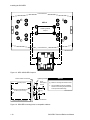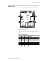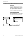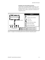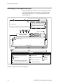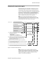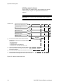
1
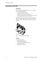
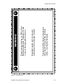
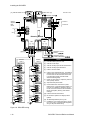
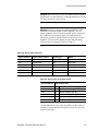
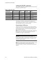
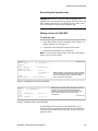
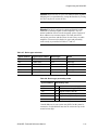
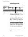
SIGA-REL
Technical Reference Manual
P/N 387348 • Rev 2.0 • 08JUN01
DEVELOPED BY
Edwards Systems Technology
6411 Parkland Drive
Sarasota, FL 34243
(941) 739-4300
COPYRIGHT NOTICE
Copyright © 2001 Edwards Systems Technology, Inc.
This manual is copyrighted by Edwards Systems Technology,
Inc. (EST). You may not reproduce, translate, transcribe, or
transmit any part of this manual without express, written
permission from EST.
This manual contains proprietary information intended for
distribution to authorized persons or companies for the sole
purpose of conducting business with EST. If you distribute any
information contained in this manual to unauthorized persons,
you have violated all distributor agreements and may be
subject to legal action.
CREDITS
This manual was designed and written by the EST Technical
Services - Documentation Department, Sarasota.
DOCUMENT HISTORY
Date
Revision
Reason for change
14FEB01
1.0
Initial release
08JUN01
2.0
Added: testing information; FMRC agency information; drawing
for preaction/deluge sprinkler systems; compatibility information
for releasing solenoid valves; programming statements
Deleted: Halon as a listed agent
Edited: compatible panel information; specification values for
consistency; drawings for nongeneric captions and missing
information; programming rules; cautions on accepting actual
devices; drawings in operational description
Content
Important information • ii
Locating related documents • iii
Installation codes and standards • iv
Documentation conventions • vi
Chapter 1
Installing the SIGA-REL • 1.1
Introducing the SIGA-REL • 1.2
Fire suppression systems • 1.3
Compatible panels and devices • 1.5
Specifications • 1.7
Mounting the SIGA-REL • 1.9
Setting abort mode and delay times • 1.11
Reading LEDs • 1.13
Wiring the SIGA-REL • 1.14
Chapter 2
Programming the SIGA-REL • 2.1
Programming the SIGA-REL in the 2-SDU • 2.2
Programming the SIGA-REL in the 3-SDU (Revision 1.5) • 2.6
Programming the SIGA-REL in the 3-SDU (Revision 2.0) • 2.10
System testing • 2.14
Chapter 3
Operational description • 3.1
Integrating the Releasing Module fire alarm systems • 3.2
Developing a fire suppression plan • 3.4
Releasing fire suppression agents • 3.5
Chapter 4
SIGA-REL trouble indications • 4.1
SIGA-REL indications on EST2 panels • 4.2
SIGA-REL indications on EST3 panels • 4.4
Index • Z.1
SIGA-REL Technical Reference Manual
i
Content
Important information
Limitation of liability
This product has been designed to meet the requirements of
NFPA Standard 72, 1999 Edition; Underwriters Laboratories,
Inc., Standard 864, 8th Edition; and Underwriters Laboratories of
Canada, Inc., Standard ULC S527. Installation in accordance
with this manual, applicable codes, and the instructions of the
authority having jurisdiction (AHJ) is mandatory. EST shall not
under any circumstances be liable for any incidental or
consequential damages arising from loss of property or other
damages or losses owing to the failure of EST products beyond
the cost of repair or replacement of any defective products. EST
reserves the right to make product improvements and change
product specifications at any time.
While every precaution has been taken during the preparation of
this manual to ensure the accuracy of its contents, EST assumes
no responsibility for errors or omissions.
FCC warning
This equipment can generate and radiate radio frequency energy.
If this equipment is not installed in accordance with this manual,
it may cause interference to radio communications. This
equipment has been tested and found to comply within the limits
for Class B computing devices pursuant to Subpart B of Part 15
of the FCC Rules. These rules are designed to provide reasonable
protection against such interference when this equipment is
operated in a commercial environment. Operation of this
equipment is likely to cause interference, in which case the user
at his own expense, will be required to take whatever measures
may be required to correct the interference.
ii
SIGA-REL Technical Reference Manual
Content
Locating related documents
EST2 documentation
A library of related documents supports the EST2 product line.
Here is a complete list of the EST2 library:
•
•
•
•
•
•
EST2 Installation and Service Manual (P/N 270186)
EST2 Network Supplement Manual (P/N 270894)
EST2 System Operations Manual (P/N 270188)
EST2 System Programming Manual (P/N 270187)
EST2 Installation Sheets (P/N 3100056)
2-SDU Help
EST3 documentation
A library of related documents supports the EST3 product line.
Here is a complete list of the EST3 library:
•
•
•
•
•
•
EST3 Installation and Service Manual (P/N 270380)
EST3 System Operations Manual (P/N 270382)
EST3 System Programming Manual (P/N 270381)
EST3 Installation Sheets (P/N 3100051)
EST3 International Supplement Manual (P/N 270925)
3-SDU Help
Signature Series documentation
The Signature Series Intelligent Smoke and Heat Detectors
Applications Bulletin (P/N 270145) provides instructions and
illustrations for various arrays of smoke and heat detectors.
The Signature Series Component Installation Manual (P/N
270497) supports the installation of the Signature Series detectors
and modules.
The Serial Number Log Book (P/N 270267) provides a
convenient means for recording the serial number of each
Signature device installed in the fire alarm system.
Speaker and strobe documentation
The EST Speaker Application Guide (P/N 85000-0033) provides
information about the placement and layout of speakers for fire
alarm signaling and emergency voice communications.
The EST Strobe Applications Guide (P/N 85000-0049) provides
information for the placement and layout of strobes for fire alarm
signaling.
SIGA-REL Technical Reference Manual
iii
Content
Installation codes and standards
The Signature Series fire detection devices are designed to meet
the requirements of NFPA Standard 72, 1999 Edition;
Underwriters Laboratories, Inc. Standard 864, 8th Edition and
Underwriters Laboratories of Canada, Inc. Standard ULC S527.
Other related codes and standards are listed below. Information
contained in this document is intended to serve as a guide.
Installation in accordance with the instruction sheets (provided
with Signature Series devices), applicable codes, and the
instructions of the AHJ is mandatory.
National Fire Protection Agency
NFPA®
National Fire Protection Agency (NFPA)
1 Batterymarch Park PO Box 9101
Quincy, MA 02269-9101
NFPA 11
Low-Expansion Foam
NFPA 11A
Medium- and High-Expansion Foam Systems
NFPA 12
Carbon Dioxide Extinguishing Systems
NFPA 13
Sprinkler Systems
NFPA 15
Water Spray Fixed Systems for Fire Protection
NFPA 16
Deluge Foam-Water Sprinkler and Foam-Water
Spray systems
NFPA 17
Dry Chemical Extinguishing Systems
NFPA 70
National Electric Code
NFPA 72
National Fire Alarm Code
Underwriters Laboratories, Inc.
R
UL 864
Underwriters Laboratories, Inc. (ULI)
333 Pfingsten Road
Northbrook, IL 60062-2096
Standard for Control Units for Fire Protective
Signaling Systems
Underwriters Laboratories of Canada
R
ULC S527
iv
Underwriters Laboratories of Canada (ULC)
7 Crouse Road
Scarborough, Ontario M1R 3A9
Standard for Control Units for Fire Alarm
Systems
SIGA-REL Technical Reference Manual
Content
Factory Mutual Research Corporation
Factory Mutual Research
Corporation
1151 Boston Providence Turnpike
PO Box 9102
Norwood, MA 02062
1011-1012
Deluge and Preaction Systems
European standards
73/23/EEC
Low Voltage Directive
89/336/EEC
Electromagnetic Compatibility
Directive
as amended by 9/31/EEC
EN50130-4; 1995
Immunity requirements for
Components of Fire, Intruder, and
Social Alarm Systems
EN55022:1995
Limits and Methods of
Measurement of Radio
Disturbance Characteristics of
Information Technology
Components
Other requirements
Other requirements that affect the installation of this system
include:
•
•
State and local building codes
AHJ
SIGA-REL Technical Reference Manual
v
Content
Documentation conventions
Notices throughout this manual inform the reader of practices and
conditions, which will affect physical safety, occupant safety,
equipment performance, and efficiency. Notices appear as
warnings, cautions, and notes.
Warnings
Warnings appear whenever property damage, injury, or loss of
life may occur through the neglect of safe practices and
conditions. You will see warnings in the following format:
Warning! Disconnect all wiring on TB4 of the SIGA-REL
(release circuits 1 and 2) during system service. Disabled points
will not prevent activation of the release circuits. Failure to
follow these instructions may result in loss of life, serious injury,
or property damage.
Cautions
Cautions alert you to practices that may damage equipment,
software, or project databases. For example, the manual provides
a caution against corrupting the database.
Caution! Do not use the Accept Actual function in the Signature
Mapping tool. Accepting actual data may corrupt the database by
causing it to see every accepted device as two devices.
Notes
Notes provide instructions to help you save time or avoid wasting
it. For example, a note may inform you that a system does not
support a function so you will not waste time looking for it.
Note: EST2 systems do not support matrix groups.
vi
SIGA-REL Technical Reference Manual
Chapter 1
Installing the SIGA-REL
Summary
The SIGA-REL supports a variety of fire suppression
applications. These applications include sprinkler systems and
automatic fire extinguishing systems. When you install the
SIGA-REL, follow agency and local requirements along with the
instructions in this manual.
Content
Introducing the SIGA-REL • 1.2
Description • 1.2
Features • 1.2
Fire suppression systems • 1.3
Sprinkler systems • 1.3
Automatic fire extinguishing systems • 1.4
Compatible panels and devices • 1.5
Panels • 1.5
Power supplies • 1.5
Solenoid polarizing relays • 1.5
Abort stations • 1.5
Service disconnect stations • 1.5
Releasing solenoid valves • 1.6
Listing agencies • 1.6
Specifications • 1.7
Mounting the SIGA-REL • 1.9
Setting abort mode and delay times • 1.11
Choosing the abort mode • 1.11
Setting the DIP switches • 1.11
Reading LEDs • 1.13
Wiring the SIGA-REL • 1.14
Observing equipment and personal safety • 1.14
Running the wires • 1.14
SIGA-REL Technical Reference Manual
1.1
Installing the SIGA-REL
Introducing the SIGA-REL
Description
The SIGA-REL Releasing Module (Figure 1-1) is a Signature
Series component consisting of:
•
•
•
•
•
Two supervised release circuits
Two supervised prerelease circuits
One supervised manual release input circuit
One supervised abort circuit for a normally-open abort switch
One first alarm output relay (Form C contact)
The SIGA-REL controls operations for deluge, preaction, and
automatic fire extinguishing systems. The module controls the
release of gas and other fire suppression agents through release
solenoids.
RELEASE028.CDR
Figure 1-1: SIGA-REL Releasing Module
Features
The SIGA-REL includes:
•
•
•
•
•
1.2
Deluge sprinkler operation
Preaction sprinkler operation
Automatic fire extinguishing operation
Selectable abort modes
Intelligent microprocessor
SIGA-REL Technical Reference Manual
Installing the SIGA-REL
Fire suppression systems
Sprinkler systems
The SIGA-REL works with two types of sprinkler systems:
deluge and preaction. The primary difference between both
systems is the type of sprinkler head (or nozzle) that terminates
the pipes. Table 1-1 outlines the Factory Mutual Research
Corporation (FMRC) requirements for deluge and preaction
systems. FMRC also requires FM-approved compatible release
valves. See Table 1-4 in Compatible panels and devices.
Table 1-1: FM approval requirements for deluge and preaction sprinkler systems
Specification
Value
Standby operation
90 hours
Alarm operation
10 minutes
NFPA style
Class A (Style D or E) or Class A (Style 2, 5, 6, or 7)
Deluge sprinkler systems
In Deluge sprinkler systems, open-valve sprinkler heads
terminate pipes connected to a water supply controlled by a single
valve. When the system detects a fire it automatically opens the
valve to allow the waterflow through all of the sprinkler heads.
Deluge sprinklers are useful for applications that require the
simultaneous discharge of water through every sprinkler.
The following fire detection systems meet FRMC requirements
for deluge systems:
•
•
•
•
•
Wet pilot sprinkler line
Dry pilot sprinkler line
Hydraulic rate-of-rise
Pneumatic rate-of-rise
Electric
Preaction sprinkler systems
In preaction sprinkler systems, closed-valve sprinkler heads
terminate pipes connected directly to a water supply. The water
supply is usually in the same area as the sprinklers and the pipes
are supervised for air pressure. Preaction sprinklers are useful
where it is important to prevent the accidental discharge of water.
The following fire detection systems meet FRMC requirements
for preaction systems:
•
•
•
Hydraulic rate-of-rise
Pneumatic rate-of-rise
Electric
SIGA-REL Technical Reference Manual
1.3
Installing the SIGA-REL
Automatic fire extinguishing systems
Warning! Improper applications of fire suppression agents can
lead to property damage, injury, or loss of life. Consult the
applicable NFPA documents and the authority having jurisdiction
(AHJ) for more information.
Automatic fire extinguishing systems automatically detect and
extinguish fires. They require no manual input because detectors
automatically activate releasing solenoids or sprinkler valves.
Table 1-2 provides a list of the fire suppression agents and the
applicable NFPA documents.
Table 1-2: Fire suppression agents and NFPA documentation
Agent
NFPA documentation
Low-expansion foam
NFPA 11
Medium- and high-expansion foam
NFPA 11A
CO2
NFPA 12
Sprinklers
NFPA 13
Water spray
NFPA 15
Foam-water
NFPA 16
Dry chemicals
NFPA 17
Note: On September 16, 1986, the Montreal Protocol on
Substances determined that Halon is an ozone-depleting
substance. The SIGA-REL is not listed for use with Halon.
Table 1-3 outlines the FMRC requirements for automatic fire
extinguishing systems.
Table 1-3: FM approval requirements for automatic fire extinguishing systems
Specification
Value
Standby operation
24 hours
Alarm operation
10 minutes
NFPA style
B or D
FMRC documentation
FMRC Approval Guide (Volume 1)
1.4
SIGA-REL Technical Reference Manual
Installing the SIGA-REL
Compatible panels and devices
Panels
The SIGA-REL is compatible with EST2 and EST3 fire alarm
control panels. You may install the SIGA-REL in any of the
following enclosures:
•
•
•
•
•
2-WB(X) series
RACCR series
3-RCC series
3-CAB series
MFC-A
Note: Maintain a 1-inch (25.4 mm) minimum clearance all
around the SIGA-REL. The clearance space must also comply
with the National Electrical Code.
Power supplies
The SIGA-REL is compatible with the following power supplies:
•
•
•
•
•
•
•
2-PPS(-220)
2-PPS/6A(-220)
SIGA-APS(-220)
3-BPS/M(-220)
3-PPS/M(-220)
BPS6(-220)*
BPS10(-220)*
*Not compatible with FMRC sprinkler applications that require
90 hours of standby.
Solenoid polarizing relays
Use the RELA-EOL with the SIGA-REL. For more information,
see the RELA-EOL installation sheet.
Abort stations
The SIGA-REL is only compatible with normally-open,
momentary-action abort stations. Abort stations must be listed
with the appropriate agencies in your area. See Listing agencies.
Service disconnect stations
The SIGA-REL is only compatible with listed service disconnect
stations that are normally-closed (minimum 2.0 Amps). Service
disconnect stations must be listed with the appropriate agencies in
your area. See Listing agencies.
SIGA-REL Technical Reference Manual
1.5
Installing the SIGA-REL
Releasing solenoid valves
Releasing solenoid valves must be listed with the appropriate
agencies in your area. FMRC requires FM-approved solenoid
release valves. Table 1-4 lists the FM-approved solenoid release
valves that work with the Releasing Module.
Table 1-4: FM-approved solenoid release valves
Group
Company
Model
A
Skinner
LV2LBX25
D
ASCO
8210G207
E
Skinner
73218BN4UNLVNDC111C2
F
Skinner
73212BN4TNLVNDC322C2
G
Skinner
71395SN2ENJINOH111C2
For other listing agencies that may apply to your area, see Listing
agencies.
Listing agencies
Listing agencies include:
•
•
•
1.6
Factory Mutual Research Corporation (FMRC)
Underwriters Laboratories, Inc. (UL)
Underwriters Laboratories Canada (ULC)
SIGA-REL Technical Reference Manual
Installing the SIGA-REL
Specifications
*Riser current: Total current of output circuits is limited to the
power riser input current (up to 4 amps) minus 170 mA.
Power riser
Input voltage
24 Vdc
Supervisory current
25 mA, max.
Alarm current
170 mA min., 4 A max.
(depends on output circuit loading)
Line resistance
See Table 1-5.
Release circuits, TB4
Output (release circuit 1)
2 A @ 24 Vdc, max. (*See riser current.) TB4-1 and TB4-2
Output (release circuit 2)
2 A @ 24 Vdc, max. (*See riser current.) TB4-3 and TB4-4
Valves per circuit
4 valves, max.
Line resistance
See Table 1-6.
End of line device
47 kW resistor
Prerelease circuits, TB5
Output (prerelease circuit 1)
2 A @ 24 Vdc, max. (*See riser current.) TB5-1 and TB5-2
Output (prerelease circuit 2)
2 A @ 24 Vdc, max. (*See riser current.) TB5-3 and TB5-4
Line resistance
See Table 1-6.
End of line device
47 kW resistor
Manual release input circuit, TB3-1 and TB3-2
Line resistance
25 W/wire, #18 AWG = 3800 ft (0.75 mm2 = 1158 m)
End of line device
47 kW resistor
Circuit capacitance
0.1 mF, max.
Abort circuit, TB3-3 and TB3-4
Line resistance
25 W/wire, #18 AWG = 3800 ft (0.75 mm2 = 1158 m)
End of line device
47 kW resistor
Circuit capacitance
0.1 mF, max.
First alarm contact, TB2
Contact rating
3 A @ 24 Vdc, (resistive load) Form C
Signature Data line, TB1
Operating voltage
15.2 to 19.95 Vdc
Supervisory current
1 mA
Alarm current
1 mA
Line resistance
See the installation sheet of the Signature loop controller.
Maximum quantity
Ten SIGA-RELs per loop
SIGA-REL Technical Reference Manual
1.7
Installing the SIGA-REL
Environmental conditions
Operating temperature
32 to 120 °F (0 to 49 °C)
Storage temperature
-4 to 140 °F (-20 to 60 °C)
Humidity
0 to 93% RH, non-condensing
Table 1-5: Power riser
Total riser
current
(Amps)
Distance from SIGA-REL to power supply
#12 AWG
2.5 mm2
#14 AWG
1.5 mm2
Wire
resistance
(W per wire)
4.0
29 ft
8.84 m
20 ft
6.10 m
0.050
3.5
34 ft
10.36 m
23 ft
7.01 m
0.057
3.0
39 ft
11.89 m
27 ft
8.23 m
0.067
2.5
47 ft
14.33 m
32 ft
9.75 m
0.080
2.0
59 ft
17.98 m
40 ft
12.19 m
0.100
1.5
78 ft
23.77 m
53 ft
16.15 m
0.133
1.0
118 ft
35.97 m
80 ft
24.38 m
0.200
Table 1-6: Prerelease and release circuits (per circuit)
Total riser
current
(Amps)
1.8
Distance from SIGA-REL to signals
#12 AWG
2.5 mm2
#14 AWG
1.5 mm2
Wire
resistance
(W per wire)
2.00
176 ft
53.64 m
120 ft
36.58 m
0.300
1.75
202 ft
61.57 m
137 ft
41.76 m
0.343
1.50
235 ft
71.63 m
160 ft
48.77 m
0.400
1.25
282 ft
85.95 m
192 ft
58.52 m
0.480
1.00
353 ft
107.59 m
240 ft
73.15 m
0.600
0.50
706 ft
215.19 m
480 ft
146.30 m
1.200
SIGA-REL Technical Reference Manual
Installing the SIGA-REL
Mounting the SIGA-REL
Caution! The SIGA-REL and the MFC-A require separation
between power-limited and nonpower-limited wiring. See the
MFC-A installation sheet for details about power-limited wiring
in that enclosure. See Wiring the SIGA-REL for details about
power-limited wiring on the SIGA-REL.
To mount the SIGA-REL to the MFC-A:
1
Align the SIGA-REL to the designated mounting holes in the
MFC-A (Figure 1-2 and Figure 1-3).
2
Secure the SIGA-REL to the MFC-A with the washers and
screws provided.
3
Run the wiring from the SIGA-REL to the fire suppression
components through the conduit knockouts in the MFC-A.
MFC-A
Releasing Module
#6-32 self-tapping screws
#6 Flat Washers
RELEASE025.CDR
Figure 1-2: Mounting the SIGA-REL
To mount the SIGA-REL in other enclosures:
1
Use the SIGA-REL to mark the mounting hole locations
(Figure 1-4).
2
Drill the mounting holes at the marks made in step 1
(mounting hole diameter = 0.125 in or 3.175 mm).
3
Mount the SIGA-REL in the cabinet with the screws and
washers provided.
SIGA-REL Technical Reference Manual
1.9
Installing the SIGA-REL
Conduit knockout
MFC-A
Releasing Module
footprint
Conduit knockout
RELEASE024.CDR
Figure 1-3: MFC-A/SIGA-REL footprint
Interior surface of enclosure
Mounting space
Mounting hole diameter is
0.125 in (or 3.175 mm)
Interior surface of enclosure
Notes
Releasing Module
#6-32
Self-tapping
Screws
[1] Mark the mounting hole locations here.
2
[1]
See compatible enclosure installation
sheets for the routing of power-limited
and nonpower-limited wiring.
RELEASE036.CDR
#6 Flat Washers
Figure 1-4: SIGA-REL mounting holes in compatible cabinets
1.10
SIGA-REL Technical Reference Manual
Installing the SIGA-REL
Setting abort mode and delay times
Choosing the abort mode
Table 1-7 provides descriptions for the SIGA-REL abort modes.
Note: Abort modes 3 and 4 do not comply with UL or ULC.
Table 1-7: Abort mode descriptions
Mode
Description
1 (Factory default)
If the abort is initiated before the automatic delay timer expires, it
will prevent the releasing action. The automatic delay timer will
continue to run while the abort is active. When the abort is
restored, the release will occur with the expiration of the
automatic delay timer or the abort delay timer, whichever occurs
last.
2
If the abort is initiated before the automatic delay timer expires, it
will prevent the releasing action. The automatic delay timer will
stop running. When the abort is restored, the automatic delay
timer will resume and the release will occur with the expiration of
the timer.
3 (Industrial Risk Insurers)
To be recognized as valid, the abort must be active when the
second alarm is received. When the abort is restored, the
release will occur with the expiration of the abort delay timer (set
for 10 sec). If the valid abort is held for more than 10 seconds,
the automatic delay timer is inactive. If the valid abort is held for
less than 10 seconds, the automatic delay timer operates as
programmed.
4 (International)
If the abort is initiated before the automatic delay timer expires, it
will prevent the releasing action. The automatic delay timer will
stop running. When the abort is restored, the automatic delay
timer will reset and commence time from t = 0. The release will
occur with the expiration of the timer setting minus 10 seconds.
Setting the DIP switches
Warning! Press the Reset switch at the fire alarm control panel
whenever you change the DIP switch settings. Otherwise, the
new settings will not take effect.
Figure 1-5 shows the default DIP switch settings of the
SIGA-REL. Tables 1-8 through 1-11 provide the DIP switch
settings for the SIGA-REL abort modes and delay time settings.
SIGA-REL Technical Reference Manual
1.11
Installing the SIGA-REL
ON
ON
1 = On
TB6
0 = Off
0 0 0 1
1 2 3 4
SW
TB3
1 0 0 1
5 6 7 8
SW
TB2
Releasing
Module
RELEASE026.CDR
Figure 1-5: SIGA-REL DIP switches
Table 1-8: Abort mode settings
Abort mode
SW1
SW2
1 (Default)
0
0
2
0
1
3 (IRI)
1
0
4 (International)
1
1
Table 1-9: Manual delay time settings
Time delay
SW3
SW4
No delay
0
0
10 seconds (Default)
0
1
20 seconds
1
0
30 seconds
1
1
Table 1-10: Automatic delay time settings
Time delay
SW5
SW6
SW7
10 seconds
0
0
0
20 seconds
0
0
1
30 seconds
0
1
0
40 seconds
0
1
1
50 seconds (Default)
1
0
0
Table 1-11: Abort delay time settings
Time delay
1.12
SW8
No delay
0
10 seconds (Default)
1
SIGA-REL Technical Reference Manual
Installing the SIGA-REL
Reading LEDs
Figure 1-6 shows the location of the LEDs on the SIGA-REL.
TB6
TB3
TB1
TB2
Releasing Module
DS1
DS2
DS4
DS3
DS5
DS6 DS7
TB4
TB5
RELEASE027.CDR
Figure 1-6: SIGA-REL LEDs
Table 1-12 explains the color, patterns, and functions for each
LED.
Table 1-12: SIGA-REL LEDs
LED
Color
Pattern
Function
DS1
Red
Flashing
Data (alarm conditions)
DS2
Green
Flashing
Data (normal conditions)
DS3
Red
Steady
Alarm
DS4
Green
Steady
Power
DS5
Yellow
Steady
Abort
DS6
Yellow
Steady
Trouble
DS7
Red
Steady
Release active
SIGA-REL Technical Reference Manual
1.13
Installing the SIGA-REL
Wiring the SIGA-REL
Observing equipment and personal safety
To ensure safety with the SIGA-REL:
1
Copy Figure 1-7.
2
Cut out the photocopied warning along the perforated line.
3
Post the warning next to the SIGA-REL.
4
Inform all appropriate personnel about the posted warning, its
location, and its importance.
5
Require compliance with the warning during all installation
and service procedures.
Warning! Observe static-sensitive material handling practices
while installing or servicing the SIGA-REL. Electrostatic
discharge may damage the equipment and activate the release
circuits.
Running the wires
Wire SIGA-REL according to Figure 1-8.
1.14
SIGA-REL Technical Reference Manual
SIGA-REL Technical Reference Manual
Failure to follow these instructions
may result in loss of life, serious
injury, or property damage.
Disabled points will not prevent
activation of the release circuits.
Disconnect all wiring on TB4 of the
Releasing Module (release circuits
1 and 2) during system service.
WARNING!
RELEASE039.CDR
Installing the SIGA-REL
Figure 1-7: Warning notice
1.15
Installing the SIGA-REL
[11] Manual release circuit [5]
[3]
[4]
Abort circuit [11]
[5]
RELEASE023.CDR
First alarm output
[8]
TB6
Class A
Signature
Data
Circuit
In
+
_
Out
+
_
1 2 3 4
TB3
_
4
3
2
1
1 2 3
TB2
TB1
+
_
+
24 Vdc in
24 Vdc out
4
3
2
1
Releasing Module
TB4
1
_ 2 3
_ 4
+
+
[1] [2] [7] [8]
[1] [2] [7] [8]
[10]
[11]
[6]
[5]
Prerelease circuit 1
(pulsed 15/60/Steady)
Notes
[1]
Four RELA-EOLs per circuit, max.
RELA-EOL
RELA-EOL
[2]
Class B, 24 Vdc output
[3]
Class B, normally-open manual release station
[4]
Class B, normally-open abort station
1
2
3
4
[6]
1
2
3
4
RELA-EOL
1
2
3
4
[6]
1
2
3
4
RELA-EOL
1
2
3
4
[6]
RELA-EOL
[6]
[10]
[11]
Release
circuit 2
RELA-EOL
[6]
Prerelease circuit 2
(steady)
Release
circuit 1
RELA-EOL
[6]
TB5
1_ 2 3_ 4
+
+
1
2
3
4
RELA-EOL
1
2
3
4
[6]
[5]
1
2
3
4
[5]
Listed 47 kW EOL resistor
[6]
Listed 24 Vdc nonpolarized valve. The releasing
solenoid valve wiring is not supervised for wireto-wire shorts. Run the connection to the valve
in conduit within 20 feet of the RELA-EOL
Solenoid Polarizing Relay.
[7]
Polarity of circuit shown in supervisory state. On
alarm, polarity reverses.
[8]
Supervised and power-limited.
[9]
Power-limited when connected to a powerlimited source. If nonpower-limited, maintain 1/4
inch (6.4 mm) separation. Otherwise, use FPL,
FPLR, or FPLP in accordance with the National
Electric Code (NEC). Destroy power-limited
markings.
[10] Listed service disconnect station
[11] Not included in preaction or deluge sprinkler
systems
[12] Ten Releasing Modules per loop, max.
13
Installations, which include other wiring, require
FPL, FPLR, FPLP, or equivalent NEC-approved
wiring for all power-limited wiring.
Figure 1-8: SIGA-REL wiring
1.16
SIGA-REL Technical Reference Manual
Chapter 2
Programming the SIGA-REL
Summary
The SIGA-REL works with EST2 and EST3 systems. The 2-SDU
and the 3-SDU (Revision 1.5) recognize the SIGA-REL as three
SIGA-UM modules that occupy six addresses. The 3-SDU
(Revision 2.0) does not require you to select SIGA-UMs because
it recognizes the SIGA-REL.
In all systems, the programming procedures for the SIGA-REL
are almost identical. The greatest differences exist in the required
rules and the configuration of AND groups. The SIGA-REL
programming steps require strict adherence. Follow each
instruction carefully.
Content
Programming the SIGA-REL in the 2-SDU • 2.2
Adding the SIGA-REL to the database • 2.2
Labeling the SIGA-REL components • 2.4
Programming an AND group • 2.4
Reconciling the Signature map • 2.4
Writing rules for the SIGA-REL • 2.4
Programming the SIGA-REL in the 3-SDU (Revision 1.5) • 2.6
Adding the SIGA-REL to the database • 2.6
Labeling the SIGA-REL components • 2.8
Programming an AND group • 2.8
Reconciling the Signature map • 2.9
Writing rules for the SIGA-REL • 2.9
Programming the SIGA-REL in the 3-SDU (Revision 2.0) • 2.10
Adding the SIGA-REL to the database • 2.10
Labeling the SIGA-REL components • 2.12
Programming an AND group • 2.12
Reconciling the Signature map • 2.13
Writing rules for the SIGA-REL • 2.13
System testing • 2.14
Testing EST2 systems • 2.14
Testing EST3 systems • 2.14
SIGA-REL Technical Reference Manual
2.1
Programming the SIGA-REL
Programming the SIGA-REL in the 2-SDU
Adding the SIGA-REL to the database
Warning! This information was prepared for users who are
proficient in every aspect of 2-SDU programming. DO NOT
attempt to program the SIGA-REL if your certification is not
current. Failure to do this may result in loss of life, serious injury,
or property damage.
Caution! If you are adding other Signature Series devices to the
project database, add the SIGA-REL last. Adding devices after
the SIGA-REL may disrupt the addressing scheme. The
SIGA-REL is a single module with six serial numbers, but the
2-SDU recognizes it as three SIGA-UMs. Addresses will differ
for each installation, but they must be consecutive.
The SIGA-REL provides only one serial number label. When you
scan in the SIGA-REL, only the first two serial numbers will
appear in the database.
To add the SIGA-REL to the database:
Break Chain button
2.2
1
Scan in the SIGA-REL serial number label.
2
In the SDC Configuration, ensure that four blank addresses
follow the first two addresses.
3
Add two more SIGA-UMs (four address spaces) to the
database to fill in the four empty addresses.
4
In the Signature Series mapping tool, access the Actual vs.
Expected Data dialog box (F9 key).
5
Click Break Chain and select the appropriate address.
6
Commit the expected data.
7
In the SDC Configuration, configure the SIGA-REL
(SIGA-UM) addresses in strict accordance with Tables 2-1
and 2-2.
SIGA-REL Technical Reference Manual
Programming the SIGA-REL
Caution! Do not use the Accept Actual function in the Signature
Mapping tool. Accepted data may corrupt the database by causing
it to see every device as two devices.
Warning! DO NOT configure the third and fifth SIGA-UM
addresses as common outputs or audio amplifiers. Any offnormal condition will activate the automatic release sequence if
these addresses are common outputs. The Drill switch will
activate the prerelease and the release circuits if they are audio
amplifiers. You must select the device types and personality
codes exactly as prescribed in Tables 2-1 and 2-2.
Table 2-1: Device type selections
Typical address
Typical serial number
Device type
Model
7*
5300411525*
Monitor
SIGA-UM
8*
5300411532*
Pull
SIGA-UM
9*
5300411549*
DoorControl**
SIGA-UM
10*
5300411556*
None
SIGA-UM
11*
5300411563*
DoorControl**
SIGA-UM
12*
5300411570*
None
SIGA-UM
Table 2-2: Device type personality codes
Typical address
Personality code
7*
3
N/O Active - Non-Latching (Class B)
8*
1
N/O Alarm Latching (Class B)
9*
16
Signal Output (Class B)
10*
0
No personality
11*
16
Signal Output (Class B)
12*
0
No personality
*Actual addresses in your system may differ, but they must be
consecutive. Serial numbers must also be consecutive up to the
second-to-last digit.
**Select one of the following: DamperControl, DoorControl, or
FanControl. Ensure that the selected device type is exclusive for
SIGA-REL use.
SIGA-REL Technical Reference Manual
2.3
Programming the SIGA-REL
Labeling the SIGA-REL components
In the Object Configuration, assign the labels and messages listed
in Table 2-3 to the SIGA-UM.
Table 2-3: SIGA-REL labels
Device Type
Typical address
Label
Message
Model
Monitor
0207*
Abort
Abort
SIGA-UM
Pull
0208*
Manual
Manual
SIGA-UM
DoorControl
0209*
Release_1
Release_1
SIGA-UM
None
0210*
Release_2
Release_2
SIGA-UM
DoorControl
0211*
Prerelease_1
Prerelease_1
SIGA-UM
None
0212*
Prerelease_2
Prerelease_2
SIGA-UM
*The addresses in Table 2-3 demonstrate the importance of
ensuring that the SIGA-REL occupies six consecutive addresses.
The actual addresses in your system may differ.
Programming an AND group
AND groups function as cross zones. For more information about
programming AND groups, see the EST2 System Programming
Manual and the 2-SDU Help.
Note: Every device contained in each (SIGA-REL) AND group
must include a rule with an output statement like the one in
[ALARM1]. See Figure 2-1 for the details.
Reconciling the Signature map
Caution! Do not use Accept Actual in the Signature Series
mapping tool. Accepted devices may appear as two devices in the
SDC database and corrupt it. Use the Break Chain and Commit
Expected functions to reconcile the Signature map.
Writing rules for the SIGA-REL
To write the rules:
2.4
1
In the Rules Editor, write the mandatory rules in Figure 2-1
and the optional rules in Figure 2-2.
2
Compile the rules and run the required conversions.
3
Download and upload the new information.
SIGA-REL Technical Reference Manual
Programming the SIGA-REL
Note: See the system testing section, at the end of this chapter,
before you test of your system.
[ALARM1]
ALARM 'ALARM_1' : ON 'PRERELEASE_1';
[ALARM2]
ALARM 'ALARM_2' : ON 'PRERELEASE_1';
Note: [ALARM_1] and [ALARM_2] require the
addition of two Signature Series alarm devices to
the SDC Configuration. Make sure that the object
labels in the rules match the labels assigned in
the Object Configuration.
[RELEASE]
DEFINE AND 'AND_GROUP1' : DELAY 10,
ON 'RELEASE_1';
[RESET]
DEFINE SYSRESET 'MCMN1' : OFF 'PRERELEASE_1',
OFF 'RELEASE_1';
RELEASE010.CDR
[DUMP]
ALARM 'MANUAL' : ON 'RELEASE_1';
Figure 2-1: Mandatory rules of the SIGA-REL
[DRILL]
DEFINE DRILL 'MCMN1' : ON 'PRERELEASE_1';
[LED1]
CONFIRMATION 'PRERELEASE_1' :
ON 'LED_1_1';
[LED2]
CONFIRMATION 'RELEASE_1' :
ON 'LED_1_2';
Note: [LED1] and [LED2] require the addition of
an LED module to the MCM Configuration. Make
sure that the labels for the LEDs match the labels
assigned to them in the Object Configuration.
RELEASE032.CDR
Figure 2-2: Optional rules for the SIGA-REL
Avoid using the Drill switch to test the SIGA-REL. If you
activate a Drill, press the Reset switch to deactivate it. The
deactivation of the Drill switch, alone, will not silence the
prerelease tones.
SIGA-REL Technical Reference Manual
2.5
Programming the SIGA-REL
Programming the SIGA-REL in the 3-SDU (Revision 1.5)
Adding the SIGA-REL to the database
Warning! This information was prepared for users who are
proficient in every aspect of 3-SDU (Revision 1.5) programming.
DO NOT attempt to program the SIGA-REL if your certification
is not current. Failure to do this may result in loss of life, serious
injury, or property damage.
Caution! If you are adding other Signature Series devices to the
project database, add the SIGA-REL last. Adding devices after
the SIGA-REL may disrupt the addressing scheme. The
SIGA-REL is a single module with six serial numbers, but the
3-SDU (Revision 1.5) recognizes it as three SIGA-UMs.
Addresses will differ for each installation, but they must be
consecutive.
The SIGA-REL provides only one serial number label. When you
scan in the SIGA-REL, only the first two serial numbers will
appear in the database.
To add the SIGA-REL to the database:
Break Chain button
2.6
1
Scan in the SIGA-REL serial number label.
2
In the DSDC configuration (Loop X Modules tab), ensure
that four blank addresses follow the first two addresses.
3
Add two more SIGA-UMs (four address spaces) to the
database to fill in the four empty addresses.
4
In the Signature Series mapping tool, access the Actual vs.
Expected Data dialog box (F9 key).
5
Click Break Chain and select the appropriate address.
6
Commit the expected data.
7
In the DSDC configuration, configure the SIGA-REL
(SIGA-UM) addresses in strict accordance with Tables 2-4
and 2-5.
SIGA-REL Technical Reference Manual
Programming the SIGA-REL
Caution! Do not use the Accept Actual function in the Signature
Mapping tool. Accepted data may corrupt the database by causing
it to see every device as two devices.
Warning! DO NOT configure the third and fifth SIGA-UM
addresses as common outputs or audio amplifiers. Any offnormal condition will activate the automatic release sequence if
these addresses are common outputs. The Drill switch will
activate the prerelease and the release circuits if they are audio
amplifiers. You must select the device types and personality
codes exactly as prescribed in Tables 2-4 and 2-5.
Table 2-4: Device type selections
Typical address
Typical serial number
Device type
Model
126*
5300411525*
Monitor
SIGA-UM
127*
5300411532*
Pull
SIGA-UM
128
5300411549*
SupervisedOutput
SIGA-UM
129*
5300411556*
None
SIGA-UM
130*
5300411563*
SupervisedOutput
SIGA-UM
131*
5300411570*
None
SIGA-UM
Table 2-5: Device type personality codes
Typical address
Personality code
126*
3
N/O Active - Non-Latching (Class B)
127*
1
N/O Alarm Latching (Class B)
128*
16
Signal Output (Class B)
129*
0
No personality
130*
16
Signal Output (Class B)
131*
0
No personality
*Actual addresses in your system may differ, but they must be
consecutive. Serial numbers must also be consecutive up to the
second-to-last digit.
SIGA-REL Technical Reference Manual
2.7
Programming the SIGA-REL
Labeling the SIGA-REL components
In the Object configuration, assign the labels and messages listed
in Table 2-6 to the SIGA-UMs.
Table 2-6: SIGA-REL labels
Device Type
Typical address
Label
Message
Model
Monitor
126*
Abort
Abort
SIGA-UM
Pull
127*
Manual
Manual
SIGA-UM
SupervisedOutput
128*
Release_1
Release_1
SIGA-UM
None
129*
Release_2
Release_2
SIGA-UM
SupervisedOutput
130*
Prerelease_1
Prerelease_1
SIGA-UM
None
131*
Prerelease_2
Prerelease_2
SIGA-UM
*The addresses in Table 2-6 demonstrate the importance of
ensuring that the SIGA-REL occupies six consecutive addresses.
The actual addresses in your system may differ.
Programming an AND group
AND groups function as cross zones; matrix groups function as
counting zones. For more information about programming AND
groups and matrix groups, see the EST3 System Programming
Manual and the 3-SDU Help.
Note: Every device contained in each (SIGA-REL) AND group
must include a rule with an output statement like the one in
[ALARM1]. See Figure 2-3 for the details.
Warning! Set the AND group to an Activate number 2 or
greater. Activate number 1 will cause the AND group to become
an OR group, and any activation of Alarm_1 or Alarm_2 will
activate the release sequence.
Note: For preaction operation, set the Activate number to 1. This
will cause the AND group to become an OR group. Any
activation of Alarm_1 or Alarm_2 will then activate the release
sequence.
2.8
SIGA-REL Technical Reference Manual
Programming the SIGA-REL
Reconciling the Signature map
Caution! Do not use Accept Actual in the Signature Series
mapping tool. Accepted devices may appear as two devices in the
SDC database and corrupt it. Use the Break Chain and Commit
Expected functions to reconcile the Signature map.
Writing rules for the SIGA-REL
To write the rules:
1
In the Rules Editor, write the mandatory rules in Figure 2-3
and the optional rules in Figure 2-4.
2
Compile the rules and run the required conversions.
3
Download and upload the new information.
Note: See the system testing section, at the end of this chapter,
before you test of your system.
[ALARM1]
ALARM 'ALARM_1' :
ON 'PRERELEASE_1';
[ALARM2]
ALARM 'ALARM_2' :
ON 'PRERELEASE_1';
[ANDGROUP DUMP]
ALARM 'AND_GROUP1' :
DLYA 10,
ON 'RELEASE_1',
DLYR 10;
[DUMP]
ALARM 'MANUAL' : ON -HIGH 'RELEASE_1';
RELEASE011.CDR
Note: [ALARM_1] and [ALARM_2] require the addition
of alarm devices to the panel configuration. Make sure
that the object labels match the labels assigned to
them in the Object Configuration.
Figure 2-3: Mandatory rules for the SIGA-REL
[DRILL]
DRILL :
ON 'PRERELEASE_1';
[LED1]
RLYCFG 'PRERELEASE_1' :
ON 'LED_1_1';
[LED2]
RLYCFG 'RELEASE_1' :
ON 'LED_1_2';
Note: [LED1] and [LED2] require the addition of an LED
module to the Cabinet Configuration (Modules tab,
operator layer). Make sure that the labels for the LEDs
match the labels assigned to them in the Object
Configuration.
RELEASE033.CDR
Figure 2-4: Optional rules for the SIGA-REL
Avoid using the Drill switch to test the SIGA-REL. If you
activate a Drill, press the Reset switch before you deactivate it.
The deactivation of the Drill switch, alone, will not silence the
prerelease tones.
SIGA-REL Technical Reference Manual
2.9
Programming the SIGA-REL
Programming the SIGA-REL in the 3-SDU (Revision 2.0)
Adding the SIGA-REL to the database
Warning! This information was prepared for users who are
proficient in every aspect of 3-SDU (Revision 2.0) programming.
DO NOT attempt to program the SIGA-REL if your certification
is not current. Failure to do this may result in loss of life, serious
injury, or property damage.
Caution! If you are adding other Signature Series devices to the
project database, add the SIGA-REL last. Adding devices after
the SIGA-REL may disrupt the addressing scheme. The
SIGA-REL is a single module with six serial numbers, but the
3-SDU (Revision 2.0) recognizes it as three SIGA-RELs.
Addresses will differ for each installation, but they must be
consecutive.
The SIGA-REL provides only one serial number label. When you
scan in the SIGA-REL, only the first two serial numbers will
appear in the database.
To add the SIGA-REL to the database:
Break Chain button
2.10
1
Scan in the SIGA-REL serial number label.
2
In the DSDC configuration (Loop X Modules tab), ensure
that four blank addresses follow the first two addresses.
3
Add two more SIGA-RELs (four address spaces) to the
database to fill in the four empty addresses.
4
In the Signature Series mapping tool, access the Actual vs.
Expected Data dialog box (F9 key).
5
Click Break Chain and select the appropriate address.
6
Commit the expected data.
7
In the DSDC configuration, configure the SIGA-REL
addresses in strict accordance with Tables 2-7 and 2-8.
SIGA-REL Technical Reference Manual
Programming the SIGA-REL
Caution! Do not use the Accept Actual function in the Signature
Mapping tool. Accepted data may corrupt the database by causing
it to see every device as two devices.
Warning! DO NOT configure the third and fifth SIGA-REL
addresses as common outputs or audio amplifiers. Any offnormal condition will activate the automatic release sequence if
these addresses are common outputs. The Drill switch will
activate the prerelease and the release circuits if they are audio
amplifiers. You must select the device types and personality
codes exactly as prescribed in Tables 2-7 and 2-8.
Table 2-7: Device type selections
Typical address
Typical serial number
Device type
Model
126*
5300411525*
Monitor
SIGA-REL
127*
5300411532*
Pull
SIGA-REL
128
5300411549*
SupervisedOutput
SIGA-REL
129*
5300411556*
None
SIGA-REL
130*
5300411563*
SupervisedOutput
SIGA-REL
131*
5300411570*
None
SIGA-REL
Table 2-8: Device type personality codes
Typical address
Personality code
126*
3
N/O Active - Non-Latching (Class B)
127*
1
N/O Alarm Latching (Class B)
128
16
Signal Output (Class B)
129*
0
No personality
130*
16
Signal Output (Class B)
131*
0
No personality
*Actual addresses in your system may differ, but they must be
consecutive. Serial numbers must also be consecutive up to the
second-to-last digit.
SIGA-REL Technical Reference Manual
2.11
Programming the SIGA-REL
Labeling the SIGA-REL components
In the Object configuration, assign the labels and messages listed
in Table 2-9 to the SIGA-REL.
Table 2-9: SIGA-REL labels
Device Type
Typical address
Label
Message
Model
Monitor
126*
Abort
Abort
SIGA-REL
Pull
127*
Manual
Manual
SIGA-REL
SupervisedOutput
128*
Release_1
Release_1
SIGA-REL
None
129*
Release_2
Release_2
SIGA-REL
SupervisedOutput
130*
Prerelease_1
Prerelease_1
SIGA-REL
None
131*
Prerelease_2
Prerelease_2
SIGA-REL
*The addresses in Table 2-9 demonstrate the importance of
ensuring that the SIGA-REL occupies six consecutive addresses.
The actual addresses in your system may differ.
Programming an AND group
AND groups function as cross zones; matrix groups function as
counting zones. For more information about programming AND
groups and matrix groups, see the EST3 System Programming
Manual and the 3-SDU Help.
Note: Every device contained in each (SIGA-REL) AND group
must include a rule with an output statement like the one in
[ALARM1]. See Figure 2-5 for the details.
Warning! Set the AND group to an Activate number 2 or
greater. Activate number 1 will cause the AND group to become
an OR group, and any activation of Alarm_1 or Alarm_2 will
activate the release sequence. Check only Q1 for each device in
the listbox labeled “Devices in Selected Group.” For Q1, only a
detector in alarm will count as a device activation. If you check
Q2, Q3, or Q4 the release circuit may accidentally activate for
maintenance issues.
Note: For preaction operation, set the Activate number to 1. This
will cause the AND group to become an OR group. Any
activation of Alarm_1 or Alarm_2 will then activate the release
sequence.
2.12
SIGA-REL Technical Reference Manual
Programming the SIGA-REL
Reconciling the Signature map
Caution! Do not use Accept Actual in the Signature Series
mapping tool. Accepted devices may appear as two devices in the
SDC database and corrupt it. Use the Break Chain and Commit
Expected functions to reconcile the Signature map.
Writing rules for the SIGA-REL
To write the rules:
1
In the Rules Editor, write the mandatory rules in Figure 2-5
and the optional rules in Figure 2-6.
2
Compile the rules and run the required conversions.
3
Download and upload the new information.
Note: See the system testing section, at the end of this chapter,
before you test of your system.
[ALARM1]
ALARM 'ALARM_1' :
ON 'PRERELEASE_1';
[ALARM2]
ALARM 'ALARM_2' :
ON 'PRERELEASE_1';
[ANDGROUP DUMP]
ALARM 'AND_GROUP1' :
DLYA 10,
ON 'RELEASE_1',
DLYR 10;
[DUMP]
ALARM 'MANUAL' : ON -HIGH 'RELEASE_1';
RELEASE011.CDR
Note: [ALARM_1] and [ALARM_2] require the addition
of alarm devices to the panel configuration. Make sure
that the object labels match the labels assigned to
them in the Object Configuration.
Figure 2-5: Mandatory rules for the SIGA-REL
[DRILL]
DRILL :
ON 'PRERELEASE_1';
[LED1]
RLYCFG 'PRERELEASE_1' :
ON 'LED_1_1';
[LED2]
RLYCFG 'RELEASE_1' :
ON 'LED_1_2';
Note: [LED1] and [LED2] require the addition of an LED
module to the Cabinet Configuration (Modules tab,
operator layer). Make sure that the labels for the LEDs
match the labels assigned to them in the Object
Configuration.
RELEASE033.CDR
Figure 2-6: Optional rules for the SIGA-REL
Avoid using the Drill switch to test the SIGA-REL. If you
activate a Drill, press the Reset switch before you deactivate it.
The deactivation of the Drill switch, alone, will not silence the
prerelease tones.
SIGA-REL Technical Reference Manual
2.13
Programming the SIGA-REL
System testing
Warning! Disconnect the release circuit until system testing is
complete and the system is stable.
Testing EST2 systems
Allow the system sufficient time to stabilize after the initial
startup or download. Before you test the system, access the SDC
Status tool in the 2-SDU. Do not test the system if the status
LEDs indicate anything pending or in progress. This includes:
•
•
•
•
Mapping
Device new starts
Resets
Restarts
Testing EST3 systems
Allow the system sufficient time to stabilize after the initial
startup or download. Before you test the system, access the
DSDC Status tool in the 3-SDU. Do not test the system if the
status LEDs indicate anything pending or in progress. This
includes:
•
•
•
•
Mapping
Device new starts
Resets
Restarts
In the 3-SDU (Rev 2.0), you can test the system while the Device
Supervision LED is on. The Device Supervision LED may be on
longer for larger loops.
2.14
SIGA-REL Technical Reference Manual
Chapter 3
Operational description
Summary
The SIGA-REL works with manual and automatic inputs. The
operational description explains how the SIGA-REL fits into the
fire alarm system and behaves during fire alarms.
Content
Integrating the Releasing Module with fire alarm systems • 3.2
System overview • 3.2
Preaction/deluge sprinkler systems • 3.2
Automatic fire extinguishing systems • 3.3
Developing a fire suppression plan • 3.4
Releasing fire suppression agents • 3.5
Understanding the automatic release sequence • 3.5
Initiating manual releases • 3.6
SIGA-REL Technical Reference Manual
3.1
Operational description
Integrating the Releasing Module with fire alarm systems
System overview
The SIGA-REL is a Signature Series module that interfaces a
Signature loop controller with fire suppression components. The
Releasing Module works with sprinkler systems and automatic
extinguishing systems. Sprinklers include preaction and deluge
systems. Automatic fire extinguishing systems include the fire
suppression agents listed in Table 1-2.
Note: See Installing the SIGA-REL for details about its wiring,
specifications, mounting, and abort mode settings. For wiring
resistance calculations, see pages 1.7 and 1.8.
Preaction/deluge sprinkler systems
Figure 3-1 illustrates the integration of the SIGA-REL with the
fire alarm control panel and a preaction or deluge sprinkler
system. Sprinkler systems do not include service disconnect
stations, abort stations, or manual release stations.
Legend
Fire alarm control panel
Signature Series smoke detectors
Signature loop controller
M
Class A wiring required
M
Signature Series modules
Horn circuit
Strobe circuit
RELEASE037.CDR
M
Releasing Module
RELA-EOL
Preaction or deluge system 1
RELA-EOL
Preaction or deluge system 2
Figure 3-1: Integration of the Releasing Module with a deluge or preaction sprinkler system
3.2
SIGA-REL Technical Reference Manual
Operational description
Automatic fire extinguishing systems
The SIGA-REL also supports automatic extinguishing systems,
which provide manual actuation of abort, release, and servicedisconnect functions. Figure 3-2 illustrates the integration of the
SIGA-REL with a fire alarm control panel in an automatic fire
extinguishing system.
Legend
RELEASE012.CDR
Fire alarm control panel
Signature Series smoke detectors
Signature loop controller
M
Signature Series modules
Horn circuit
Class A wiring required
M
A
MR
M
Releasing Module
Strobe circuit
SD
Service disconnect station
A
Manual abort station
MR
Manual release station
SD
RELA-EOL
Fire suppression system 1
SD
RELA-EOL
Fire suppression system 2
Figure 3-2: Integration of the Releasing Module with an automatic extinguishing system
SIGA-REL Technical Reference Manual
3.3
Operational description
Developing a fire suppression plan
The Releasing Module consists of two releasing circuits, which
provide fire suppression in two separate areas. The computer
room illustrated in Figure 3-3 is a typical application for the
Releasing Module.
Fire alarm control panel
RELEASE015.CDR
Signature loop controller
A
MR
Release circuit 1
Releasing Module
SD
RELA-EOL
SD
RELA-EOL
Release circuit 2
2
1
Raised floor
Slab
Legend
Signature Series smoke detectors
MR
Strobe circuit
Horn circuit
SD
Service disconnect station
A
Manual abort station
Wall-mounted agent release nozzle
Ceiling-mounted agent release nozzle
Extinguishing
agent
storage
cylinder
Manual release station
Figure 3-3: Typical computer room application
3.4
SIGA-REL Technical Reference Manual
Operational description
Releasing fire suppression agents
Understanding the automatic release sequence
The automatic release sequence requires an AND group (cross
zone) or a matrix group (counting zone). AND groups and matrix
groups require fire alarm signals from designated Signature
Series devices. These logic groups are programmable through a
laptop computer and the System Definition Utility (SDU).
Figure 3-4 explains the automatic release sequence.
Note: EST2 systems do not support matrix groups. See
Programming the SIGA-REL for AND group rules. To create
AND groups and matrix groups, see the System Programming
Manual and the SDU Online Help for your system.
RELEASE013.CDR
Time line (See details below.)
[1]
[2]
[3]
[4]
[5]
First alarm relay
Automatic delay timer
Prerelease circuits
Release circuits
[1]
A detector signals the first alarm. This event
simultaneously activates the:
• First alarm relay
• Prerelease strobe circuit (steady On)
• Prerelease horn circuit (15 pulses per minute)
[2]
Selectable
automatic delay time
(10 to 50 seconds)
A detector in the protected area signals a second alarm and
meets the AND group conditions.* The automatic delay timer
then starts its countdown and the prerelease horn circuit
changes to 60 pulses per minute.
*AND group and matrix group conditions depend on programming.
[3]
10 seconds before the automatic delay timer expires, the prerelease
(horn) circuit changes to steady On.
[4]
The automatic delay timer expires and the release circuits activate.
[5]
A manual reset at the fire alarm control panel deactivates the release
solenoids and the Releasing Module returns to the normal state.
Figure 3-4: Automatic release sequence
Note: Prerelease circuit 1 supports audible notification
appliances that sound prerelease and release signals. Audible
prerelease signals sound at 15 and 60 pulses per minute. The
audible release signal is a steady tone. Prerelease circuit 2
supports visual notification appliances.
SIGA-REL Technical Reference Manual
3.5
Operational description
Initiating manual releases
The operation of a manual release station initiates the manual
release sequence. Figure 3-5 explains the manual release
sequence.
Warning! You CANNOT abort the manual release sequence.
RELEASE014.CDR
Time line (See details below.)
[1]
[2]
[3]
[4]
First alarm relay
Manual delay timer
Prerelease circuits
Release circuits
[1]
An active manual release station disables automatic
operation and the abort function and simultaneously
activates the:
•
•
•
•
Selectable
manual delay time
(0 to 30 seconds)
Manual delay timer
Prerelease circuit
Prerelease strobe circuit (steady On)
Prerelease horn circuit (60 pulses per minute)
[2]
10 seconds before the expiration of the manual delay
timer, the pre-release horn changes from 60 pulses
per minute to steady On.
[3]
The manual delay timer expires and the release circuits activate.
[4]
A manual reset at the fire alarm control panel deactivates the release
solenoids and the Releasing Module returns to the normal state.
Figure 3-5: Manual release sequences
3.6
SIGA-REL Technical Reference Manual
Chapter 4
SIGA-REL trouble indications
Summary
You may occasionally see SIGA-REL messages on the front
panel display. Table 4-1 provides trouble indications for EST2
panels. Table 4-2 provides trouble indications for EST3 panels.
Content
SIGA-REL indications on EST2 panels • 4.2
SIGA-REL indications on EST3 panels • 4.4
SIGA-REL Technical Reference Manual
4.1
SIGA-REL trouble indications
SIGA-REL indications on EST2 panels
Warning! Disconnect all wiring on TB4 of the SIGA-REL
(release circuits 1 and 2) during system service. Disabled points
will not prevent activation of the release circuits. Failure to
follow these instructions may result in loss of life, serious injury,
or property damage.
After the successful completion of the programming process, the
fire alarm control panel will reset itself. Upon reset, device
supervision may cause the panel to generate a Dev/Line fault for
each SIGA-REL circuit. This is a normal indication, and it should
go away within minutes. Table 4-1 lists the indications you may
see for the SIGA-REL on the 2-LCD.
Table 4-1: Releasing Module indications
Device
Condition
LED
2-LCD message
Abort
Short
Monitor
None, unless there is another event
Open
Trouble
Open Fault
Abort*
Short
Alarm
1st Fire Alarm
Manual*
Open
Trouble
Open Fault
Manual*
Short
Trouble
Short Fault
Prerelease_1*
Open
Trouble
Open Fault
Prerelease_1*
Short
Trouble
Dev/Line Flt
Prerelease_2*
Open
Trouble
Open Fault
Prerelease_2*
Abort
Manual
Prerelease_1
Prerelease_2
Release_1
Release_2
No riser
Trouble
Dev/Line Flt
Device (Abort, Manual, Prerelease_1, Prerelease_2,
Release_1, or Release_2)*
Release_1
Short
Trouble
Short Fault
Release_1*
Open
Trouble
Open Fault
Release_1*
Manual
Prerelease_1
Prerelease_2
4.2
SIGA-REL Technical Reference Manual
SIGA-REL trouble indications
Table 4-1: Releasing Module indications (Continued)
Device
Condition
LED
2-LCD message
Release_2
Short
Trouble
Dev/Line Flt
Release_2*
Open
Trouble
Open Fault
Release_2*
*Message requires user programming.
SIGA-REL Technical Reference Manual
4.3
SIGA-REL trouble indications
SIGA-REL indications on EST3 panels
Warning! Disconnect all wiring on TB4 of the SIGA-REL
(release circuits 1 and 2) during system service. Disabled points
will not prevent activation of the release circuits. Failure to
follow these instructions may result in loss of life, serious injury,
or property damage.
When programming is complete, the fire alarm control panel will
reset itself, reconstruct the line datacard, and map it. Upon reset,
device supervision may cause the panel to generate a common
trouble active for each SIGA-REL circuit. This is a normal
indication, and it should go away within minutes. Table 4-2 lists
the indications you may see for the SIGA-REL on the 3-LCD.
Table 4-2: Releasing Module indications
Device
Condition
LED
3-LCD message
Abort
Short
Monitor
MONITOR ACT (Abort)
Open
Trouble
COMMON TRBL ACT
Abort*
Expanded message: TROUBLE OPEN ACT
Short
Alarm
PULL STATION ACT
Manual*
Open
Trouble
COMMON TRBL ACT
Manual*
Expanded message: TROUBLE OPEN ACT
Short
Trouble
COMMON TRBL ACT
Prerelease_1*
Expanded message: TROUBLE SHRT ACT
Open
Trouble
COMMON TRBL ACT
Prerelease_1*
Expanded message: TROUBLE OPEN ACT
Short
Trouble
COMMON TRBL ACT
Prerelease_2*
Expanded message: TROUBLE SHRT ACT
Open
Trouble
COMMON TRBL ACT
Prerelease_2*
Expanded message: TROUBLE OPEN ACT
No riser
Trouble
COMMON TRBL ACT
Device (Abort, Manual, Prerelease_1, Prerelease_2,
Release_1, or Release_2)*
Expanded message: INTRNL TRBL ACT
Manual
Prerelease_1
Prerelease_2
Abort
Manual
Prerelease_1
Prerelease_2
Release_1
Release_2
4.4
SIGA-REL Technical Reference Manual
SIGA-REL trouble indications
Table 4-2: Releasing Module indications (Continued)
Device
Condition
LED
3-LCD message
Release_1
Short
Trouble
COMMON TRBL ACT
Release_1*
Expanded message: TROUBLE SHRT ACT
Open
Trouble
COMMON TRBL ACT
Release_1*
Expanded message: TROUBLE OPEN ACT
Short
Trouble
COMMON TRBL ACT
Release_2*
Expanded message: TROUBLE SHRT ACT
Open
Trouble
COMMON TRBL ACT
Release_2*
Expanded message: TROUBLE OPEN ACT
Release_2
*Message requires user programming.
SIGA-REL Technical Reference Manual
4.5
SIGA-REL trouble indications
4.6
SIGA-REL Technical Reference Manual
Index
2
E
2-SDU programming • 2.2–2.5
enclosures. See panels, compatible
environmental conditions • 1.8
EST2 documentation • iii
EST3 documentation • iii
European standards • v
3
3-SDU
(Revision 1.5) programming • 2.6–2.9
(Revision 2.0) programming • 2.10–2.13
A
abort
circuit • 1.7, 1.16, 4.2, 4.4
delay time settings • 1.12
modes • 1.11, 1.12
stations, compatible • 1.5
adding the SIGA-REL
to 2-SDU databases • 2.2–2.3
to 3-SDU databases • 2.6–2.7, 2.10–2.11
agencies, listing • iv–v, 1.6
AHJ (authority having jurisdiction) • ii, iv, v
AND groups, SIGA-REL
in 2-SDU programming • 2.4, 3.5
in 3-SDU (Revision 1.5) programming • 2.8, 3.5
in 3-SDU (Revision 2.0) programming • 2.12, 3.5
automatic delay time settings • 1.12
automatic fire extinguishing systems • 1.4, 3.3
automatic release sequence • 3.5
C
cautions • vi, 2.2, 2.3, 2.6, 2.7, 2.10, 2.11
circuits
abort • 1.7, 1.16, 4.2, 4.4
manual release • 1.7, 1.16, 3.6, 4.2, 4.4
prerelease • 1.7, 1.16, 3.5, 3.6, 4.2, 4.4
release • 1.7, 1.16, 3.5, 3.6, 4.2, 4.3, 4.4, 4.5
codes and standards, installation • iv–v, 1.4
compatible panels and devices • 1.5–1.6
counting zones. See matrix groups, SIGA-REL
cross zones. See AND groups, SIGA-REL
D
deluge sprinkler systems • 1.3, 3.2
developing a fire suppression plan • 3.4
DIP switch settings • 1.11–1.12
distances, wire • 1.8
documentation, related • iii
SIGA-REL Technical Reference Manual
F
first alarm contact • 1.7
FCC warning • ii
FMRC (Factory Mutual Research Corporation) • v,
1.3, 1.4
L
labeling SIGA-REL components • 2.4, 2.8, 2.12
LEDs • 1.13
listing agencies • iv, v, 1.6
M
manual delay time settings • 1.12
manual release circuit • 1.7, 1.16, 3.6, 4.2, 4.4
manual release sequence • 3.6
matrix groups, SIGA-REL • 2.8, 2.12, 3.5
MFC-A • 1.9–1.10
modes
abort • 1.11, 1.12
delay time • 1.12
Montreal Protocol on Substances • 1.4
N
NFPA (National Fire Protection Agency) • iv
O
operational description • 3.1–3.6
P
panels, compatible • 1.5
power riser • 1.7
power supplies, compatible • 1.5
prerelease circuits • 1.7, 1.16, 3.5, 3.6, 4.2, 4.4
preaction sprinkler systems • 1.3, 3.2
programming
2-SDU • 2.2–2.5
3-SDU (Revision 1.5) • 2.6–2.9
3-SDU (Revision 2.0) • 2.10–2.13
Z.1
Index
R
reading LEDs • 1.13
reconciling the Signature map
in the 2-SDU • 2.4
in the 3-SDU (Revision 1.5) • 2.9
in the 3-SDU (Revision 2.0) • 2.13
related documentation • iii
release circuits • 1.7, 1.16, 3.5, 3.6, 4.2, 4.3, 4.4, 4.5
releasing solenoid valves, compatible • 1.6
requirements, FM
for automatic fire extinguishing systems • 1.4
for sprinkler systems • 1.3
resistances, wire • 1.7, 1.8
rules, SIGA-REL
in the 2-SDU • 2.5
in the 3-SDU (Revision 1.5) • 2.9
in the 3-SDU (Revision 2.0) • 2.13
S
safety precautions • 1.14
sequences
automatic release • 3.5
manual release • 3.6
service disconnect stations, compatible • 1.5
settings, DIP switch • 1.11–1.12
SIGA-REL
2-SDU labels for • 2.4
3-SDU (Revision 1.5) labels for • 2.8
3-SDU (Revision 2.0) labels for • 2.12
description • 1.2
features • 1.2
integration with fire alarm systems • 3.2
LEDs • 1.13
MFC-A mounting instructions for • 1.9–1.10
rules • 2.5, 2.9, 2.13
trouble indications on EST2 panels • 4.2–4.3
trouble indications on EST3 panels • 4.4–4.5
wiring of • 1.14, 1.16
Signature data line • 1.7
Z.2
Signature map reconciliation • 2.4, 2.9, 2.13
Signature Series documentation • iii
solenoid polarizing relays, compatible • 1.5
specifications • 1.7–1.8
speaker documentation • iii
sprinkler systems • 1.3
strobe documentation • iii
systems, fire suppression
automatic fire extinguishing • 1.4, 3.3
deluge sprinkler • 1.3, 3.2
preaction sprinklers • 1.3, 3.2
system testing • 2.14
T
trouble indications, SIGA-REL
at EST2 panels • 4.2–4.3
at EST3 panels • 4.4–4.5
testing, system • 2.14
U
UL (Underwriters Laboratories, Inc.) • iv
ULC (Underwriters Laboratories Canada) • iv
W
warning cutout • 1.15
warnings
disabling release circuits • vi, 1.15, 4.2, 4.4
FCC • ii
limitation of liability • ii
for programming the SIGA-REL • 2.2, 2.6, 2.10
for servicing the SIGA-REL • 1.14
for system testing • 2.14
wire distances • 1.8
wiring the SIGA-REL • 1.14, 1.16
writing rules for the SIGA-REL
in the 2-SDU • 2.5
in the 3-SDU (Revision 1.5) • 2.9
in the 3-SDU (Revision 2.0) • 2.13
SIGA-REL Technical Reference Manual