1
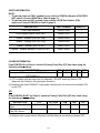
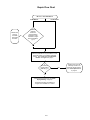
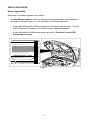
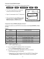
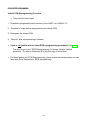
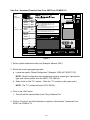
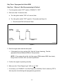
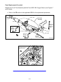
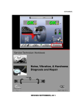
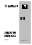
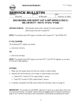
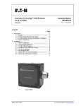
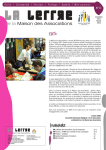
Classification:
Reference:
EC00-024b
Date:
NTB00-070b
June 7, 2004
2000-2001 MAXIMA MIL "ON" WITH DTC P0420 STORED –
THREE WAY CATALYST FUNCTION
IMPORTANT: THIS BULLETIN HAS BEEN REVISED.
•
The Service Information and Service Procedure sections of this bulletin were revised.
•
Please use this bulletin NTB00-070b for complete information.
•
Discard all previously distributed copies of NTB00-070a.
APPLIED VEHICLES:
2000-2001 Maxima (A33) - Except 2000 Maximas with
Federal Emissions Specification
IF YOU CONFIRM:
An applied vehicle has the following symptoms:
• MIL ‘ON’ with DTC P0420 stored
AND
• Vehicle runs OK and does NOT have a misfire or driveability incident
ACTIONS:
1. Confirm this bulletin applies to the vehicle you’re working on. Refer to the Repair Flow
Chart on page 3 for details.
2. Compare the current ECM part number to Chart A on page 5.
• If your ECM part number is listed in Chart A, reprogram the ECM to the latest ECM
data. See ECM REPROGRAMMING on page 6 for details. Do NOT replace any
parts in this case.
• If your ECM part number is NOT listed in Chart A, you do not have to reprogram the
ECM. But you will have to replace the Front Tube Assembly and the Front
H02S1-B1 Oxygen Sensor. See Parts Replacement on page 10 for details.
IMPORTANT: The purpose of "ACTIONS" (above) is to give you a quick idea of the work
you will be performing. You MUST closely follow the entire Repair Flow Chart and Service
Procedure (starting on page 3) as it contains information that is essential to successfully
completing this repair.
1/10
PARTS INFORMATION
NOTE:
• The below parts are ONLY needed if your vehicle’s ECM Part Number (P/N) DOES
NOT match a Current ECM P/N in Chart A (page 5).
• The below parts are NOT needed if your vehicle’s ECM Part Number (P/N)
matches a Current ECM P/N in Chart A (page 5).
DESCRIPTION
PART NUMBER
QUANTITY
Front Tube Assembly
20020-3Y400
1
Front Oxygen Sensor (H02S1-B1)
22690-2Y921
1
Gasket – Exhaust (2000 MY only)
20692-24U00
1
Gasket – Catalyst (2001 MY only)
20692-65J00
1
Gasket – Exhaust (2000-01 MY)
20691-51E01
1
Gasket – Exhaust Manifold, A (2000-01 MY)
20691-38U00
1
CLAIMS INFORMATION
If the ECM P/N IS on Chart A, submit a Primary Failed Part (PP) line claim using the
following claims coding:
DESCRIPTION
PFP OP CODE SYM DIA FRT
Reprogram ECM and perform CONSULT-II check for (2) DE98AA HC 32 0.7 hrs.
DTC P0420 (1)
(1) FRT includes sufficient labor time for diagnosis. DO NOT claim any Section "EE"
diagnostic Op Codes for this reprogram operation.
(2) Reference the final CONSULT-II reprogram function print out and use the indicated P/N
as the PFP.
OR
If the ECM P/N IS NOT on Chart A, submit a Primary Failed Part (PP) line claim using
the following claims coding:
DESCRIPTION
RPL One Front Exhaust
Tube
RPL One Front Exhaust
Gas (O2) Sensor
PFP
20020-3Y400
OP CODE
FD10AA
DE47AA
SYM
HC
DIA
32
FRT
(1)
(1)
(1) Reference the current Nissan Warranty Flat Rate Manual and use the indicated FRT.
2/10
Repair Flow Chart
MIL "On", DTC P0420 Stored
'00 MY Maxima
Bulletin does
not apply.
Use ESM
DTC P0420
Procedure.
No
'01 MY Maxima
Certified for
California
emissions?
Check Emissions
Certification Label,
underside of engine
hood (see Figure 1,
pg. 4).
Yes
Determine ECM P/N from top of CONSULT-II selfdiagnosis printout or by CONSULT ECM P/N
function. See "Check the Current ECM Part
Number" and Figure 2 on page 5.
Is
ECM P/N one
of those listed in
Chart A, pg. 5?
Yes
Perform ECM reprogramming (see "ECM
Reprogramming" on page 6):
- Download from ASIST to CONSULT-II
- Program from CONSULT-II to vehicle.
3/10
No
Replace the Front Tube
Assembly and the Front
H02S1-B1 Oxygen Sensor.
See "Parts Replacement"
on page 10.
SERVICE PROCEDURE
Bulletin Applicability
Determine if this bulletin applies to the vehicle:
1. For 2000 Maxima vehicles, check the Emissions Certification Label on the underside of
the engine hood (see Figure 1). Is the certificate for California emissions?
•
If the certificate is not for California emissions, this bulletin does not apply. Use the
P0420 Diagnostic Procedures in the ESM to further diagnose and repair.
•
If the certificate is for California emissions, proceed to Check the Current ECM
Part Number next page.
VEHICLE EMISSION CONTROL INFORMATION
¥ TEST GROUP: YNSXV03. 036A/OBD-II CERTIFIED
¥ ENGINE DISPLACEMENT: 3.0LITER
¥ EVAPORATIVE FAMILY: YNSXR0110RCC
¥ EXHAUST EMISSION CONTROL TYPE: TWC/2H02S (2) /EGR/SFI/2TWC
¥ ENGINE TUNE UP SPECIFICATIONS AND ADJUSTMENTS:
IDLE SPEED
NO OTHER ADJUSTMENTS NEEDED
HIGH IDLE SPEED
IDLE MIXTURE SETTING
NO OTHER ADJUSTMENTS NEEDED
NO OTHER ADJUSTMENTS NEEDED
INTAKE
: 0.36mm (.14IN) -HOT
EXHAUST : 0.37mm (.15IN) -HOT
15û B.T.D.C.
VALVE LASH
IGNITION TIMING
* ENGINE AT NORMAL OERATING TEMPERATURE
* ALL ACCESSORIES TURNED OFF
* KEEP THE STEERING WHEEL IN A STRAIGHT AHEAD POSITION
* CHECK WHEN RADIATOR COOLING FAN DOES NOT OPERATE
* SEE SERVICE MANUAL AND MAINTENANCE SCHEDULE FOR
ADDITIONAL INFORMATION
THIS VEHICLE CONFORMS TO U.S. EPA NLEV REGULATIONS APPLICABLE TO
GASOLINE-FUELED 2000 MODEL YEAR NEW LEV PASSENGER CARS AND
CALIFORNIA REGULATIONS APPLICABLE TO GASOLINE-FUELED 2000
MODEL YEAR NEW LEV PASSENGER CARS.
NISSN MOTOR CO., LTD.
3Y101
3
0
V
0
G
F
F
G
VQ30DE
CATALYST
TP000554
Figure 1
4/10
Check the Current ECM Part Number
With CONSULT-II “ON”, print the Freeze Frame data as follows:
START(Nissan) >> ENGINE >> Self-DIAG Results >> F.F. Data >> PRINT
• The Freeze Frame data that you’ve printed
SYSTEM
DATE
P/#
contains the ECM Part Number (P/N).
ENGINE
XX/XX/XXXX* xx:xx:xx
Current
23710-XXXXX
ECM Part
Number
• Figure 2 is an example of the F.F. Data printout.
• Once you know the current ECM part number,
go to the next step: “Compare the Current
ECM Part Number to Chart A (below).
Freeze Frame
DTC
Code
DTC RESULTS
(DTC description here)
[P0XXX]
* Example, your screen may differ.
TP020389k
Figure 2
Compare the Current ECM Part Number to Chart A:
Compare the vehicle's current ECM P/N to those shown under Current ECM P/N in Chart
A, below:
Chart A
Vehicle
Current ECM P/N
2000, M/T
23710-3Y100, -3Y101, -3Y102, -3Y103, -3Y104, -2Y065
2000, M/T w/V-tires *
23710-3Y110, -3Y111, -3Y112, -3Y113, -3Y114. -2Y075
2000, A/T
23710-3Y115, -3Y116, -3Y117, -3Y118, -3Y119, -2Y170
2000, A/T w/ TCS **
23710-3Y160, -3Y161, -3Y162, -3Y163, -3Y164, -2Y175
2001, M/T
23710-4Y900, -4Y901, -4Y902
2001, M/T w/V-tires *
23710-4Y910, -4Y911, -4Y912
2001, A/T
23710-5Y000, -5Y001, -5Y002
2001, A/T w/ TCS **
23710-5Y010, -5Y011, -5Y012
NOTE: * V-Tires = V-rated Tires
** TCS = Traction Control System
A. If your vehicle’s ECM P/N matches a P/N in the chart above:
•
Perform ECM Reprogramming, starting on page 6.
B. If your vehicle’s ECM P/N does not match a P/N in the chart above:
•
ECM Reprogramming is not necessary.
•
Replace the Front Tube Assembly and the Front H02S1-B1 Oxygen Sensor.
See Parts Replacement on page 10 for an illustration and more details.
5/10
ECM REPROGRAMMING
Vehicle ECM Reprogramming Overview
•
There are four basic steps:
1. Download reprogramming data (transfer it) from ASIST into CONSULT-II.
2. “Preparation” steps before reprogramming the vehicle ECM.
3. Reprogram the vehicle ECM.
4. “Wrap-up” after reprogramming is finished.
•
If you’re not familiar with the latest ECM reprogramming procedures, click here.
This will link you to the "ECM Reprogramming For Nissan Vehicles" general
procedure. Or, refer to Attachment A in the print copy of this bulletin.
•
For those familiar with ECM Reprogramming, please review the following steps and use
them as a Quick Reference for ECM reprogramming.
6/10
Step One: Download (Transfer) Data From ASIST Into CONSULT-II
Vehicle /
Model
Configuration
* Click the "Add" button
350Z
2004
Maxima
2003
Altima
2002
Sentra
2001
Quest
2000
Used
Space
1 File(s) selected
Vehicle Configuration #1
16MB
To 23710-XXXXX Engine #1, Trans #1, etc
To 23710-XXXXX Engine #1, Trans #1, etc.
To: 23710-XXXXX
Vehicle Configuration #2
"To"
Number
To 23710-XXXXX Engine #1, Trans #1, etc.
To 23710-XXXXX Engine #1, Trans #1, etc.
Vehicle Configuration #3
To 23710-XXXXX Engine #1, Trans #1, etc.
Pathfinder
Murano
Details:
Xterra
Add
Replaces 23710-XXXXX, -XXXXX
Frontier
8MB
Remove
More
More
Search by Code
(per bulletin only)
KeyPad
Back
Up
Show me
Main
Menu
This illustration is for example only, your vehicle may be different.
Continue
TP030621b
Figure 3
1. Select vehicle model and model year (Example: Maxima, 2001).
2. Select the correct reprogramming data:
a. Locate the specific “Model Configuration” (Example: VQ30 4A/T ASCD TCS).
NOTE: Model Configuration may include items such as engine type, transmission
type, and vehicle options such as ASCD, TCS, ABS etc.
b Select (click on) the “To” number. (Write the “To” number on the repair order.)
NOTE: The “To” number will read: 23710-XXXXX.
3. Click on the “Add” button.
•
This will add the selected data to the “File(s) Selected” list.
4. Click on “Continue” and follow directions to perform “data transfer” (download) from
ASIST into CONSULT-II.
7/10
Step Two: Preparation for Reprogramming ECM
CAUTION: DO NOT connect the CONSULT-II AC power supply for items 1 and 2.
NISSAN
ELECTRONIC CONTROL UNIT
REPROGRAMMING
1. Press SUB MODE (see Figure 4) then:
a. From the listed items, find and
select BATTERY CHARGE.
AER02C-1
INITIATE ECU REPROGRAM
SUB MODE
LIGHT
COPY
TP030620
Figure 4
2. Check the CONSULT-II’s “Charger
Input” reading (see Figure 5).
Battery Charging
CONSULT-II
Battery
Voltage
Elapsed
Discharge
Charge Time
00:01.02
00.00:00
00:01.02
Battery Voltage
NOTE:
•
Charger Input
8.32 12.15
0%
“Battery Voltage” is the voltage level
of CONSULT-II's battery.
0
"Charger Input" is the voltage level of
the vehicle’s battery. (It must be above
12 volts.)
MUST BE
ABOVE
12.00 VOLTS!
100%
10
20 30
40 50
60 70
80 90 100
Battery Charge - IDLE
•
Vehicle
Battery
Voltage
Start
Charging
MODE
Check Charger
Input without
AC power
supply
connected.
Discharge &
Charge
BACK
LIGHT
COPY
TP030625
Figure 5
CAUTION: If the “Charger Input” is below 12 volts, connect a battery charger to the
vehicle’s battery and re-check the “Charger Input”. If still not 12V, then:
•
Click here to link to the "ECM Reprogramming For Nissan Vehicles" general
procedure, or refer to Attachment A in the print copy of this bulletin.
•
The general procedure includes a list of items to check when “Charger Input” voltage
is below 12V.
8/10
Step Three: Reprogram the Vehicle ECM
Step Four: “Wrap-up” After Reprogramming is Finished
1. Turn the ignition switch "OFF" and turn CONSULT-II “OFF”.
2. Wait more than 10 seconds, then;
a. Turn the ignition switch "ON" for 2 second, then
b. Turn the ignition switch "OFF" again for 10 seconds (see Figure 6).
•
This will reset ECM “self learned” Data.
Ignition
key "ON"
Ignition
key "OFF"
2 Sec.
2 Sec.
10 Sec.
10 Sec.
TP030626b
Figure 6
3. Start the engine and check the idle speed.
•
If idle speed is too low, perform IAVL (Idle Air Volume Learning). See the
appropriate Service Manual (ESM) for this procedure.
NOTE: If the engine will not idle, hold the engine RPM at about 2000, then slowly
bring it down to an idle. IAVL can now be performed.
4. Confirm the engine is operating normally.
5. Make sure the “Check Engine Light “ (MIL) is not “ON”.
•
If necessary, use CONSULT-II and the Diagnostic (red/white) Card to erase any DTC’s
that may have stored during the reprogramming procedure.
9/10
Parts Replacement (if needed)
Replace the Front Tube Assembly and the Front H02S1-B1 Oxygen Sensor (see Figures 7
and 8 below).
• Refer to the FE section in the applicable ESM for the replacement procedures.
Rear
muffler
Bank 1 (B1)
Front Tube
Assembly
Rear cat
HO2S1-B1
Front O2
sensor B1
(BLACK)
B2
Pre-cat
H02S2-B2
Rear O2
sensor B2
(RED)
B1 Pre-Cat
Bank 2 (B2)
H02S1-B2
Front O2
sensor B2
(BLUE)
Front
H02S2-B1
Rear O2
sensor B1 (WHITE)
Figure 7
H02S1-B1
Front O2 Sensor B1
(BLACK Harness)
Front
Passenger Side
Front Strut Tower
TP030484a
Figure 8
10/10
TP010105a