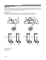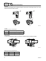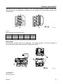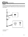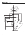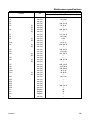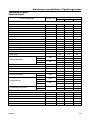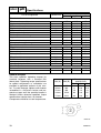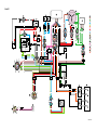
1
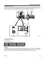
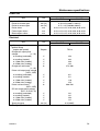
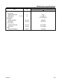
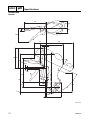
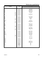
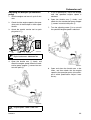
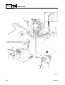
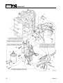
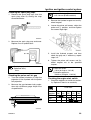
F60A
SUPPLEMENTARY
SERVICE MANUAL
292098
69W-28197-3D-1X
NOTICE
This Supplementary Service Manual has been prepared to introduce new service and new data
information for the F60 which is based on the F50. For complete information on service procedures,
it is necessary to use this Supplementary Service Manual together with the following manual.
F50A, FT50B, FT50C SERVICE MANUAL: 62Y-28197-3A-11
Important information
1
Particularly important information is distinguished in this manual by the following notations:
The Safety Alert Symbol means ATTENTION! BECOME ALERT! YOUR SAFETY IS
INVOLVED!
WARNING
Failure to follow WARNING instructions could result in severe injury or death to the machine
operator, a bystander, or a person inspecting or repairing the outboard motor.
CAUTION:
A CAUTION indicates special precautions that must be taken to avoid damage to the outboard motor.
NOTE:
A NOTE provides key information to make procedures easier or clearer.
F60A
SUPPLEMENTARY SERVICE MANUAL
©2001 by Yamaha Motor Co., Ltd.
1st Edition, July 2001
All rights reserved.
Any reprinting or unauthorized use
without the written permission of
Yamaha Motor Co., Ltd.
is expressly prohibited.
Printed in the Netherlands
Contents
General information
Specifications
Periodic checks and adjustments
Fuel system
Power unit
Lower unit
Bracket unit
GEN
INFO
SPEC
CHK
ADJ
FUEL
POWR
LOWR
BRKT
–
Electrical systems
Troubleshooting
Index
+
ELEC
TRBL
SHTG
1
2
3
4
5
6
7
8
9
General information
How to use this manual .................................................................................... 1
Manual format............................................................................................... 1
Symbols........................................................................................................ 2
Identification...................................................................................................... 3
Applicable models ........................................................................................ 3
Serial number ............................................................................................... 3
Features and benefits ....................................................................................... 4
Power unit..................................................................................................... 4
Carburetors................................................................................................... 5
Lower unit ..................................................................................................... 7
Bracket unit................................................................................................... 9
Electrical unit .............................................................................................. 10
Technical tips .................................................................................................. 11
Carburetor .................................................................................................. 11
PTT (Power Trim and Tilt) unit ................................................................... 12
Propeller selection .......................................................................................... 13
Propeller size.............................................................................................. 13
Selection..................................................................................................... 13
Predelivery checks ......................................................................................... 14
Checking the fuel system ........................................................................... 14
Checking the gear oil.................................................................................. 14
Checking the engine oil .............................................................................. 14
Checking the battery................................................................................... 14
Checking the outboard motor mounting height........................................... 14
Checking the shift/throttle cables................................................................ 15
Checking the steering system .................................................................... 15
Checking the gearshift and throttle operation............................................. 16
Checking the tilt system.............................................................................. 16
Checking the engine start switch and engine stop switch/
engine shut-off switch ............................................................................... 16
Checking the cooling water pilot hole ......................................................... 17
Test run ...................................................................................................... 17
Break-in ...................................................................................................... 17
After test run ............................................................................................... 17
69W3D1X
Specifications
General specifications.................................................................................... 18
Maintenance specifications ........................................................................... 20
Power unit................................................................................................... 20
Lower unit ................................................................................................... 24
Electrical ..................................................................................................... 24
Dimensions................................................................................................. 27
Tightening torques.......................................................................................... 32
Specified torques........................................................................................ 32
General torques.......................................................................................... 33
Periodic checks and adjustments
Special service tools ...................................................................................... 34
Maintenance interval chart............................................................................. 36
Top cowling ..................................................................................................... 37
Checking the top cowling............................................................................ 37
Fuel system ..................................................................................................... 37
Checking the fuel filter ................................................................................ 37
Power unit........................................................................................................ 37
Checking the thermostat............................................................................. 37
General............................................................................................................. 38
Checking the anodes.................................................................................. 38
Lubrication .................................................................................................. 39
Fuel system
Hose routing .................................................................................................... 40
Fuel and blowby hoses............................................................................... 40
Cooling water hose..................................................................................... 41
Fuel line and fuel filter .................................................................................... 42
Carburetor unit ................................................................................................ 43
Adjusting the dashpot (acceleration pump) ................................................ 44
69W3D1X
Power unit
Power unit........................................................................................................ 45
Checking the compression pressure .......................................................... 55
Checking the oil pressure ........................................................................... 55
Checking the cylinder bore ......................................................................... 56
Checking the piston ring grooves ............................................................... 56
Lower unit
Drive shaft and lower case............................................................................. 57
Removing the drive shaft............................................................................ 59
Disassembling the forward gear ................................................................. 59
Assembling the forward gear...................................................................... 59
Installing the drive shaft.............................................................................. 59
Shimming......................................................................................................... 60
Shimming.................................................................................................... 61
Selecting the forward gear shims ............................................................... 61
Bracket unit
Tiller handle ..................................................................................................... 63
Bottom cowling ............................................................................................... 65
Upper case....................................................................................................... 67
Disassembling the oil pan........................................................................... 71
Assembling the oil pan ............................................................................... 71
Installing the upper case............................................................................. 72
Clamp brackets ............................................................................................... 74
Adjusting the trim sensor ............................................................................ 75
Swivel bracket and steering arm ................................................................... 76
Power trim and tilt unit ................................................................................... 77
Disassembling the gear pump .................................................................... 82
Checking the valves ................................................................................... 82
Assembling the gear pump......................................................................... 83
Checking the trim sensor............................................................................ 84
69W3D1X
Electrical systems
Wiring harness ................................................................................................ 85
Ignition and ignition control system ............................................................. 86
Checking the spark plug caps .................................................................... 88
Checking the pulser coil air gap ................................................................. 88
Checking the engine start switch................................................................ 88
Starting system ............................................................................................... 89
Starter motor ................................................................................................... 90
Checking the armature ............................................................................... 91
Checking the brushes................................................................................. 91
Wiring diagram
69W3D1X
GEN
INFO
General information
How to use this manual
1
Manual format
The format of this manual has been designed to make service procedures clear and easy to understand. Use the information below as a guide for effective and quality service.
1 Parts are shown and detailed in an exploded diagram and are listed in the components list.
2 Tightening torque specifications are provided in the exploded diagrams and after a numbered
step with tightening instructions.
3 Symbols are used to indicate important aspects of a procedure, such as the grade of lubricant
and lubrication point.
4 The components list consist of parts and part quantities, as well as bolt, screw, O-ring, and hose
dimensions.
5 Service points regarding removal, checking, and installation are shown in individual illustrations
to explain the relevant procedure.
NOTE:
For troubleshooting procedures, see Chapter 9, “Troubleshooting.”
1
69W3D1X
How to use this manual
Symbols
The symbols below are designed to indicate the content of a chapter.
General information
Fuel system
GEN
INFO
Bracket unit
FUEL
Specifications
BRKT
Power unit
SPEC
Electrical systems
POWR
ELEC
Periodic checks and adjustments Lower unit
CHK
ADJ
–
+
Troubleshooting
TRBL
SHTG
LOWR
Symbols 1 to 6 indicate specific data.
1
2
3
4
5
6
T.
R.
1
2
3
4
5 Specified measurement
6 Specified electrical value
(resistance, voltage, electric current)
Special tool
Specified oil or fluid
Specified engine speed
Specified tightening torque
Symbols 7 to A in an exploded diagram indicate the grade of lubricant and the lubrication point.
7
8
9
A
0
M
A
D
C
E
7 Apply Yamaha 4-stroke motor oil
8 Apply water resistant grease (Yamaha grease A)
9 Apply molybdenum disulfide grease
0 Apply corrosion resistant grease
(Yamaha grease D)
A Apply low temperature resistant grease
(Yamaha grease C)
Symbols B to G in an exploded diagram indicate the type of sealant or locking agent and the application point.
B
C
GM
D
4
B Apply Gasket Maker®
C Apply Yamabond No. 4
D Apply LOCTITE® No. 271 (Red)
69W3D1X
E
F
G
LT
LT
LT
271
242
572
SS
E Apply LOCTITE® No. 242 (Blue)
F Apply LOCTITE® No. 572
G Apply silicon sealant
2
1
2
3
4
5
6
7
8
9
GEN
INFO
General information
Identification
1
Applicable models
This manual covers the following models.
Applicable models
F60AEHT
F60AET
Serial number
The outboard motor serial number is
stamped on a label attached to the port
clamp bracket.
1
2
3
4
Model name
Approved model code
Transom height
Serial number
Model name
F60AEHT
F60AET
3
Approved
model code
69W
Starting
serial No.
L: 500101–
L: 400101–
69W3D1X
Identification / Features and benefits
Features and benefits
1
Power unit
Based on the power unit of the field-proven F50, newly designed parts have been adopted in the
various areas to attain 60 horsepower. The newly designed parts include the intake valves, exhaust
valves, cylinder head, pistons, and the intake silencer.
Cylinder head
The shape of the combustion chamber has been changed to increase its capacity.
The diameter of the intake and exhaust valves have been enlarged to increase output.
F50
83.5 mm
(3.29 in)
F60
84.1 mm
(3.31 in)
30.0 mm (1.18 in)
84.0 mm
(3.31 in)
26.0 mm (1.02 in)
F50
84.8 mm
(3.34 in)
32.0 mm (1.26 in)
F60
26.7 mm (1.05 in)
S69W1200
1 Combustion chamber
2 Intake valve
3 Exhaust valve
69W3D1X
4
GEN
INFO
General information
Oil pump
The size of the oil pump rotor has been enlarged to increase the oil discharge volume. As a result,
reliable lubrication has been realized.
22 mm (0.87 in)
24 mm (0.94 in)
F50
F60
S69W1210
1 Rotor
2 Embossed letters for identification
Oil discharge volume
F50
21.5 L (5.68 US gal, 0.22 Imp gal)/min
F60
23.5 L (6.21 US gal, 5.17 Imp gal)/min
Carburetors
F50
Ø25
Ø30
Ø22
Ø27
To achieve the high power output of the F60, the carburetor bores have been enlarged.
F60
S69W1220
Comparison chart of carburetor bores
5
Throttle valve
Venturi
F50
ø27
ø22
F60
ø30
ø25
69W3D1X
Features and benefits
Although the main jet specification numbers of the F50 differed between cylinders, the F60 uses
main jets with the same specification number for all four cylinders due to the change in shape of the
intake silencer.
F50
:
F60
S69W1230
È Air
Comparison chart of main jet diameters
Cylinder
#1
#2
#3
#4
F50
#124
#126
#116
#114
F60
#124
#124
#124
#124
Power nozzle
The F60 uses a power nozzle in its carburetors. This nozzle provides a rich air-fuel mixture to
ensure the proper output when operating at high engine speeds.
:
S69W1240
1 Power nozzle
2 Fuel inlet
È Air-fuel mixture
69W3D1X
6
GEN
INFO
General information
Lower unit
Drive shaft
The drive shaft has been machined to accommodate the high power output. The portion that
mounts to the pinion gear has been machined with involute splines to increase durability. A section
of the midspan of the drive shaft has been reduced to 14.4 mm (0.57 in) to prevent the drive shaft
from breaking under impact loads. In addition, two grooves are provided on the drive shaft for identification purposes.
Ø14.4
95.5 mm
(3.76 in)
F60:
F50:
S69W1250
1 Grooves for identification
2 Involute splines
3 Angled splines
7
69W3D1X
Features and benefits
Forward gear bearing
The size of the forward gear bearing has been increased to accommodate the high power output of
the F60. With this increase, the coupling length of the forward gear has been extended as well. In
addition, two grooves are provided on the forward gear for identification purposes.
26.0 mm
(1.02 in)
23.2 mm
(0.91 in)
S69W1260
1 Forward gear bearing
2 Grooves for identification
3 Forward gear
Bearing comparison chart
Forward gear bearing
Forward gear
F50
22.2 mm (0.87 in)
18.5 mm (0.73 in)
F60
26.0 mm (1.02 in)
23.2 mm (0.91 in)
Propeller
The propeller of the F60 has been newly designed (69W series). The strength of the propeller
blades and the slipping resistance of the damper have been increased. The 11-, 13-, and 15-inch
propellers of the currently used 663 series will be gradually replaced by the 69W series.
69W3D1X
8
GEN
INFO
General information
Bracket unit
69W-00
PTT (Power trim and tilt) unit
Based on the 62Y type PTT unit of the F50, the internal valve and power trim and tilt motor have
been changed. The construction of the valves has been changed to increase the shut-off pressure.
The unit limits the movement of the outboard motor, which has increased in size with the increase in
its power output, and secures it in place.
31 MPa [316 kgf/cm2]
(31 MPa [316 kgf/cm2])
18 MPa [184 kgf/cm2]
(14 MPa [143 kgf/cm2])
12 MPa [122 kgf/cm2]
(10 MPa [102 kgf/cm2])
3.3 MPa [34 kgf/cm2]
(2.0 MPa [20.4 kgf/cm2])
S69W1270
Specified PTT motor output
1
2
3
4
5
9
F50A
12 V 0.15 kW
F60A
12 V 0.20 kW
PTT motor
Identification mark
Tilt piston absorber
Tilt and trim cylinder
Manual valve
6
7
8
È
É
Up-relief valve
Down-relief valve
Gear pump
Shut-off pressure of the F60 valves
Shut-off pressure of the F50 valves
69W3D1X
Features and benefits
Steering friction
The F60 tiller handle models use a newly developed, compact steering friction.
S69W1280
1 Steering friction
Electrical unit
Starter motor
The starter motor uses six magnets and four brushes to enhance its operating torque.
F50
F60
S69W1290
1
2
3
4
5
6
7
8
Bearing
Starter relay
Neutral switch
Engine start switch
Magnet
Brush
Starter motor
Battery
Operating torque
F50
2.74 N·m (0.27 kgf·m, 2.0 ft·lb)
F60
3.50 N·m (0.35 kgf·m, 2.5 ft·lb)
69W3D1X
10
GEN
INFO
General information
Technical tips
1
Carburetor
Power nozzle
The power nozzle is activated when the engine is operating at high speeds. To reduce the fuel consumption rate and the pollution of the exhaust gases, the carburetors of the F60 are set lean. Therefore, the air-fuel mixture becomes lean at high engine speeds, when greater output is needed. The
power nozzle supplies a richer fuel mixture at high engine speed to realize the optimal air-fuel ratio
to produce output.
:
:
:
S69W1300
1
2
È
É
Ê
11
Throttle valve
Power nozzle
Air
Air-fuel mixture
Fuel
69W3D1X
Technical tips
PTT (Power Trim and Tilt) unit
Shuttle piston
A ball type shut-off construction is used for both the up-shuttle and down-shuttle pistons. The ball
type realizes a reliable shut-off operation and high shut-off pressure.
F50
F60
S69W1310
1 Ball
69W3D1X
12
GEN
INFO
General information
Propeller selection
1
The performance of a boat and outboard
motor will be critically affected by the size
and type of propeller you choose. Propellers
greatly affect boat speed, acceleration,
engine life, fuel economy, and even boating
and steering capabilities. An incorrect choice
could adversely affect performance and
could also seriously damage the engine.
Use the following information as a guide for
selecting a propeller that meets the operating
conditions of the boat and the outboard
motor.
a Propeller diameter (in inches)
b Propeller pitch (in inches)
c Propeller type (propeller mark)
Selection
When the engine speed is at the full throttle
operating range (5,000–6,000 r/min), the
ideal propeller for the boat is one that provides maximum performance in relation to
boat speed and fuel consumption.
Propeller size (in)
Material
10 × 15 - G
10 3/8 × 13 - G
Propeller size
10 5/8 × 12 - G
The size of the propeller is indicated on the
propeller blade or outside of the propeller
boss.
10 3/4 × 16 - G
11 × 15 - G
Aluminum
11 5/8 × 11 - G
11 3/4 × 10 - G
12 1/4 × 8 - G
×
-
12 1/4 × 9 - G
10 1/4 × 14 - G
10 1/4 × 15 - G
10 1/4 × 16 - G
10 5/8 × 13 - G
S69W1030
Stainless
11 1/2 × 13 - G
11 3/4 × 12 - G
12 × 11 - G
×
-
S69W1040
×
-
S69W1050
13
69W3D1X
Propeller selection / Predelivery checks
Predelivery checks
1
To make the delivery process smooth and
efficient, the predelivery checks should be
completed as explained below.
Checking the engine oil
1. Check the oil level.
Checking the fuel system
1. Check that the fuel hoses are securely
connected and that the fuel tank is full
with fuel.
NOTE:
• If the engine oil is above the maximum level
mark a, drain sufficient oil until the level is
between a and b.
• If the engine oil is below the minimum level
mark b, add sufficient oil until the level is
between a and b.
Recommended engine oil:
API: SE, SF, SG, or SH
SAE: 10W-30, 10W-40, or 20W-40
Oil capacity:
Without oil filter replacement:
2.0 L (2.1 US qt, 1.8 Imp qt)
CAUTION:
This is a 4-stroke engine. Do not use premixed fuel and 2-stroke outboard motor
oil.
Checking the battery
1. Check the capacity, electrolyte level, and
specified gravity of the battery.
Battery capacity: 12 V, 70–100 Ah
Checking the gear oil
1. Check the gear oil level.
2. Check that the red and black battery
cables are securely connected.
Checking the outboard motor
mounting height
S69W1070
69W3D1X
1. Check that the anti-cavitation plate is
aligned with the bottom of the boat. If the
mounting height is too high, cavitation
will occur and propulsion will be reduced.
Also, the engine speed will increase
abnormally and cause the engine to
overheat. If the mounting height is too
low, water resistance will increase and
reduce engine efficiency.
14
GEN
INFO
General information
S69W1110
NOTE:
The optimum mounting height is affected by
the combination of the boat and the outboard
motor. To determine the optimum mounting
height, test run the outboard motor at different heights.
CAUTION:
The shift/throttle cable joint must be
screwed in a minimum of 8.0 mm (0.31 in)
e.
Checking the steering system
2. Check that the clamp brackets are
secured with the clamp bolts.
Checking the shift/throttle cables
1. Set the remote control lever or shift lever
to the neutral position and fully close the
throttle lever or throttle grip.
1. Check the steering friction for proper
adjustment.
2. Check that
smoothly.
the
steering
operates
È
2. Check that the set pin a is aligned with
the alignment mark b. Adjust if necessary.
3. Check that the alignment mark c is
aligned with the mark d. Adjust if necessary.
É
È Tiller handle model
É Remote control model
3. Check that there is no interference with
wires or hoses when the outboard motor
is steered.
15
69W3D1X
Predelivery checks
Checking the gearshift and throttle
operation
1. Check that the gearshift operates
smoothly when the remote control lever
or shift lever is shifted from neutral into
forward or reverse.
2. Check that the throttle operates smoothly
when the remote control lever or throttle
grip is shifted from the fully closed position to the fully open position a.
È
Checking the engine start switch and
engine stop switch/engine shut-off
switch
1. Check that the engine starts when the
engine start switch is turned to START.
2. Check that the engine turns off when the
engine start switch is turned to OFF.
3. Check that the engine turns off when the
engine stop switch is pushed or the
engine shut-off cord is pulled from the
engine shut-off switch.
È
É
N
F
R
É
S69W1150
È Tiller handle model
É Remote control model
Checking the tilt system
S69W1170
È Tiller handle model
É Remote control model
1. Check that the outboard motor tilts up
and down smoothly when operating the
power trim and tilt unit.
2. Check that there is no abnormal noise
produced when the outboard motor is
tilted up or down.
3. Check that there is no interference with
wires and hoses when the tilted-up outboard motor is steered.
4. Check that the trim meter points down
when the outboard motor is tilted all the
way down.
69W3D1X
16
GEN
INFO
General information
Checking the cooling watger pilot
hole
1. Start the engine, and then check that
cooling water is discharged from the
cooling water pilot hole.
0
1
2
10
S69W1190
È Hour
After test run
1. Check for water in the gear oil.
2. Check for fuel leakage in the cowling.
Test run
1. Start the engine, and then check that the
gearshift operates smoothly.
3. After a test run and while the engine is at
idle, flush the cooling water passage with
fresh water using the flushing kit.
2. Check the engine idle speed after the
engine has been warmed up.
3. Operate at trolling speed.
4. Run the outboard motor for one hour at
2,000 r/min or at half throttle, then for
another hour at 3,000 r/min or at 3/4
throttle.
5. Check that the outboard motor does not
tilt up when shifting into reverse and that
water does not flow in over the transom.
NOTE:
The test run is part of the break-in operation.
Break-in
During the test run, perform the break-in
operation in the following three stages.
1. One hour a at 2,000 r/min or at approximately half throttle.
2. One hour b at 3,000 r/min or 3/4 throttle
and one minute out of every ten at full
throttle.
3. Eight hours c at any speed, however,
avoid running at full speed for more than
five minutes.
17
69W3D1X
Predelivery checks / General specifications
General specifications
Item
Dimension
Overall length
Overall width
Overall height
(L)
Boat transom height
(L)
Weight
(with aluminum propeller)
(L)
Performance
Maximum output
Full throttle operating range
Maximum fuel consumption
Power unit
Type
Cylinder quantity
Displacement
Bore × stroke
Compression ratio
Carburetor quantity
Control system
Starting system
Ignition control system
Ignition timing
Alternator output
Enrichment system
Spark plugs
Cooling system
Exhaust system
Lubrication system
69W3D1X
2
Unit
mm (in)
mm (in)
Model
F60AEHT
F60AET
1,339 (52.7)
mm (in)
1,415 (55.7)
mm (in)
508 (20.0)
kg (lb)
kW (hp)
at 5,500 r/min
r/min
L (US gal,
lmp gal)/hr
at 6,000 r/min
cm3 (cu. in)
mm (in)
Degree
V, A
1
2
3
4
5
6
7
8
9
706 (27.8)
384 (15.1)
120.0 (265)
114.0 (251)
44.1 (60.0)
5,000–6,000
19.5 (5.15, 4.29)
In-line, 4-stroke, OHC, 8 valves
4
996 (60.8)
65.0 × 75.0 (2.56 × 2.95)
9.5
4
Tiller handle
Remote control
Electric
Microcomputer (CDI)
TDC 0–BTDC 25
12, 10
Prime Start
DPR5EA-9
Water
Through propeller boss
Wet sump
18
SPEC
Specifications
Item
Fuel and oil
Fuel type
Fuel rating
Engine oil type
Engine oil grade
Engine oil quantity
(with oil filter replacement)
Unit
PON*
RON
API
SAE
L
(US qt, lmp qt)
(without oil filter replacement)
L
(US qt, lmp qt)
Gear oil type
Gear oil grade
API
SAE
Gear oil quantity
L
(US qt, lmp qt)
Bracket
Trim angle
Degree
(at 12 degree boat transom)
Tilt-up angle
Degree
Steering angle
Degree
Drive unit
Gearshift positions
Gear ratio
Reduction gear type
Clutch type
Propeller shaft type
Propeller direction
(rear view)
Propeller identification mark
Electrical
Battery capacity
V, Ah
Model
F60AEHT
F60AET
Regular unleaded gasoline
86
91
4-stroke motor oil
SE, SF, SG, or SH
10W-30, 10W-40, or 20W-40
2.2 (2.3, 1.9)
2.0 (2.1, 1.8)
Hypoid gear oil
GL-4
90
0.43 (0.45, 0.38)
–4 to 16
69
40 + 40
F-N-R
1.85 (24/13)
Spiral bevel gear
Dog clutch
Spline
Clockwise
G
12, 70–100
* PON: Pump Octane Number (Research Octane Number + Motor Octane Number)/2
RON: Research Octane Number
19
69W3D1X
General specifications / Maintenance specifications
Maintenance specifications
2
Power unit
Item
Power unit
Minimum compression
pressure*
Lubrication oil pressure
(reference data)
Cylinder heads
Warpage limit
(lines indicate straightedge
position)
Cylinder head journal inside
diameter
Cylinders
Bore size
Taper limit
Out-of-round limit
Pistons
Piston diameter (D)
Measuring point (H)
Piston-to-cylinder clearance
Piston pin boss bore size
Oversize piston
1st
2nd
Oversize piston diameter
1st
2nd
Piston pins
Outside diameter
Unit
Model
F60AEHT
F60AET
kPa
(kgf/cm2, psi)
kPa
(kgf/cm2, psi)
at 900 r/min
880 (8.8, 125)
mm (in)
0.1 (0.004)
mm (in)
37.00–37.02 (1.4567–1.4575)
mm (in)
mm (in)
mm (in)
65.00–65.01 (2.5591–2.5594)
0.08 (0.0031)
0.01 (0.0004)
mm (in)
mm (in)
mm (in)
mm (in)
64.95–64.96 (2.5571–2.5574)
5 (0.2)
0.035–0.065 (0.0014–0.0025)
15.974–15.985 (0.6289–0.6293)
mm (in)
mm (in)
+0.25 (0.0098)
+0.50 (0.0196)
mm (in)
mm (in)
65.20–65.21 (2.5669–2.5673)
65.45–65.46 (2.5768–2.5771)
mm (in)
15.965–15.970 (0.6285–0.6287)
110 (1.1, 16)
* Measuring conditions:
Ambient temperature of 20 °C (68 °F), with throttle fully open, and spark plugs removed from all
cylinders
The figures are for reference only.
69W3D1X
20
SPEC
Specifications
Item
Piston rings
Top ring
Dimension B
Dimension T
End gap
Side clearance
2nd ring
Dimension B
Dimension T
End gap
Side clearance
Oil ring
Dimension B
Dimension T
End gap
Side clearance
Camshafts
Intake (A)
Exhaust (A)
Intake and
exhaust (B)
Camshaft journal diameter
#1
#2, #3, #4
Camshaft journal oil clearance
#1
#2, #3, #4
Maximum camshaft runout
Rocker arm shafts
Outside diameter
Rocker arms
Inside diameter
Valves
Valve clearance (cold)
Intake
Exhaust
Head diameter (A)
Intake
Exhaust
21
Unit
Model
F60AEHT
F60AET
mm (in)
mm (in)
mm (in)
mm (in)
1.17–1.19 (0.0461–0.0468)
2.30–2.50 (0.0906–0.0984)
0.15–0.30 (0.0060–0.0118)
0.02–0.06 (0.0008–0.0023)
mm (in)
mm (in)
mm (in)
mm (in)
1.47–1.49 (0.0578–0.0586)
2.60–2.80 (0.1024–0.1102)
0.30–0.50 (0.0118–0.0196)
0.02–0.06 (0.0008–0.0023)
mm (in)
mm (in)
mm (in)
mm (in)
2.36–2.48 (0.0929–0.0976)
2.75 (0.1083)
0.20–0.70 (0.0079–0.0275)
0.04–0.18 (0.0016–0.0070)
mm (in)
mm (in)
mm (in)
30.89–30.99 (1.2161–1.2200)
30.82–30.92 (1.2135–1.2175)
25.95–26.05 (1.0217–1.0256)
mm (in)
mm (in)
36.93–36.94 (1.4539–1.4543)
36.94–36.95 (1.4543–1.4547)
mm (in)
mm (in)
mm (in)
0.06–0.10 (0.0023–0.0039)
0.05–0.09 (0.0020–0.0035)
0.04 (0.0016)
mm (in)
15.98–15.99 (0.6291–0.6295)
mm (in)
16.00–16.01 (0.6299–0.6303)
mm (in)
mm (in)
0.20 ± 0.05 (0.008 ± 0.002)
0.30 ± 0.05 (0.012 ± 0.002)
mm (in)
mm (in)
31.9–32.1 (1.2560–1.2637)
26.6–26.8 (1.0472–1.0551)
69W3D1X
Maintenance specifications
Item
Face width (B)
Intake
Exhaust
Seat contact width (C)
Intake
Exhaust
Margin thickness (D)
Intake
Exhaust
Stem diameter
Intake
Exhaust
Guide inside diameter
Intake and exhaust
Stem-to-guide clearance
Intake
Exhaust
Stem runout limit
Intake
Exhaust
Valve springs
Free length
Minimum free length
Tilt limit
Connecting rods
Small-end inside diameter
Big-end inside diameter
Crankpin oil clearance
Big-end bearing thickness
Yellow
Red
Pink
Green
Crankshaft
Crankshaft journal
Diameter
Crankpin
Diameter
Runout limit
Crankcase
Crankcase main journal inside
diameter
Crankshaft main journal oil
clearance
69W3D1X
Unit
Model
F60AEHT
F60AET
mm (in)
mm (in)
1.98–2.40 (0.0780–0.0945)
2.16–2.79 (0.0850–0.1098)
mm (in)
mm (in)
1.3–1.5 (0.0512–0.0590)
1.3–1.5 (0.0512–0.0590)
mm (in)
mm (in)
0.8–1.2 (0.0315–0.0472)
1.0–1.4 (0.0394–0.0551)
mm (in)
mm (in)
5.48–5.49 (0.2157–0.2161)
5.46–5.47 (0.2150–0.2153)
mm (in)
5.50–5.51 (0.2165–0.2169)
mm (in)
mm (in)
0.01–0.03 (0.0004–0.0012)
0.03–0.05 (0.0012–0.0020)
mm (in)
mm (in)
0.05 (0.0020)
0.03 (0.0012)
mm (in)
mm (in)
mm (in)
39.85 (1.5689)
37.85 (1.4901)
1.7 (0.067)
mm (in)
mm (in)
mm (in)
15.985–15.998 (0.6293–0.6298)
36.000–36.024 (1.4173–1.4183)
0.016–0.040 (0.0006–0.0015)
mm (in)
mm (in)
mm (in)
mm (in)
1.500–1.504 (0.0591–0.0592)
1.496–1.500 (0.0589–0.0591)
1.492–1.496 (0.0587–0.0589)
1.488–1.492 (0.0586–0.0587)
mm (in)
42.984–43.000 (1.6923–1.6929)
mm (in)
mm (in)
32.984–33.000 (1.2986–1.2992)
0.04 (0.0016)
mm (in)
46.000–46.024 (1.8110–1.8120)
mm (in)
0.012–0.036 (0.0005–0.0014)
22
SPEC
Specifications
Item
Crankcase main journal
bearing thickness
Yellow
Red
Pink
Green
Oil pump
Type
Outer rotor-to-housing
clearance
Outer rotor-to-inner rotor
clearance limit
Rotor-to-cover clearance
Thermostat
Opening temperature
Fully open temperature
Valve open lower limit
Fuel pump
Discharge
Pressure
Plunger stroke
Carburetor
ID mark
Main jet
Pilot jet
Pilot screw
Float height
Engine idle speed
23
Unit
Model
F60AEHT
F60AET
mm (in)
mm (in)
mm (in)
mm (in)
1.502–1.506 (0.0591–0.0593)
1.498–1.502 (0.0590–0.0591)
1.494–1.498 (0.0588–0.0590)
1.490–1.494 (0.0587–0.0588)
mm (in)
Trochoid
0.09–0.15 (0.0035–0.0059)
mm (in)
below 0.12 (0.0047)
mm (in)
0.03–0.08 (0.0012–0.0031)
°C (°F)
°C (°F)
60 (140)
70 (158)
mm (in)
3.0 (0.12)
L (US gal,
Imp gal)/hr
at 6,000 r/min
kPa
(kgf/cm2, psi)
mm (in)
70 (18.5, 15.4)
5.85–9.65 (0.2303–0.3799)
#
#
turns out
mm (in)
r/min
69W00
124
39
1 3/4–2 3/4
5.2 (0.20)
800–900
49 (0.49, 7.0)
69W3D1X
Maintenance specifications
Lower unit
Item
Gear backlash
Pinion-to-forward gear
Pinion-to-reverse gear
Pinion shims
Forward gear shims
Reverse gear shims
Unit
mm (in)
mm (in)
mm
mm
mm
Model
F60AEHT
F60AET
0.18–0.54 (0.0071–0.0212)
0.71–1.07 (0.0280–0.0421)
0.10, 0.12, 0.15, 0.18, 0.30, 0.40, 0.50
0.10, 0.12, 0.15, 0.18, 0.30, 0.40, 0.50
0.10, 0.12, 0.15, 0.18, 0.30, 0.40, 0.50
Electrical
Item
Ignition system
Ignition timing
(engine idle speed)
Charge coil output peak
voltage
(L – Br)
at cranking (unloaded)
at cranking (loaded)
at 1,500 r/min (loaded)
at 3,500 r/min (loaded)
Charge coil resistance(*1)
(L – Br)
Pulser coil output peak voltage
(W/R – W/B)
at cranking (unloaded)
at cranking (loaded)
at 1,500 r/min (loaded)
at 3,500 r/min (loaded)
Pulser coil resistance(*1)
(W/R – W/B)
CDI unit output peak voltage
(B/O – B, B/W – B)
at cranking (unloaded)
at cranking (loaded)
at 1,500 r/min (loaded)
at 3,500 r/min (loaded)
Spark plug gap
(*1)
Unit
Model
F60AEHT
F60AET
Degree
TDC 0
V
V
V
V
Ω
159
164
168
126
272–408
V
V
V
V
Ω
9.5
5.5
11.0
15.5
396–594
V
V
V
V
mm (in)
131
141
150
112
0.9 (0.035)
The figures are for reference only.
69W3D1X
24
SPEC
Specifications
Item
Ignition control system
Oil pressure switch
ON ↔ OFF
Thermoswitch
(Gy/B – B)
OFF → ON
ON → OFF
Starter motor
Type
Output
Cranking time limit
Brushes
Standard length
Wear limit
Commutator
Standard diameter
Wear limit
Mica
Standard undercut
Wear limit
Charging system
Fuse
Lighting coil output peak
voltage
(G – G)
at cranking (unloaded)
at 1,500 r/min (unloaded)
at 3,500 r/min (unloaded)
Lighting coil resistance(*1)
(G – G)
Rectifier Regulator output
peak voltage
(R – B)
at 1,500 r/min (unloaded)
at 3,500 r/min (unloaded)
Enrichment control system
Prime Start
Unit
25
F60AEHT
F60AET
kPa
(kgf/cm2, psi)
29.4–58.8 (0.294–0.588, 4.181–8.361)
°C (°F)
°C (°F)
76–84 (169–183)
63–77 (145–170)
kW
Second
Bendix
1.1
30
mm (in)
mm (in)
17.0 (0.67)
10.0 (0.39)
mm (in)
mm (in)
33.0 (1.30)
32.0 (1.26)
mm (in)
mm (in)
0.5–0.8 (0.02–0.03)
0.2 (0.01)
A
20
V
V
V
Ω
14.0
38
86
1.2–1.8
V
V
22
27
mm (in)
24.6 (0.97)
Plunger extended length a
(*1)
Model
The figures are for reference only.
69W3D1X
Maintenance specifications
Item
Power trim and tilt system
Trim sensor
Setting resistance
Resistance
(P – B)
Fluid type
Brushes
Standard length
Wear limit
Commutator
Standard diameter
Wear limit
Mica
Standard undercut
69W3D1X
Unit
Model
F60AEHT
F60AET
Ω
Ω
9–11
9–288.3
ATF Dexron II
mm (in)
mm (in)
10 (0.39)
3.5 (0.14)
mm (in)
mm (in)
22.0 (0.87)
21.0 (0.83)
mm (in)
1.5 (0.06)
26
SPEC
Specifications
Dimensions
Exterior
L3
A1 W5
W2
W1
W6
L7
L6
L2
L1
L10
H9 H5
H2
H7
H10
H8
B6
H4
H1
C1
H3
L5
L8
H6
A2
H11
A3
L9
L4
S69W2150
27
69W3D1X
Maintenance specifications
Symbol
L1
L2
L3
L4
L5
L6
L7
L8
L9
L10
H1
H2
H3
H4
H5
H6
H7
H8
H9
H10
H11
W1
W2
W3
W4
W5
W6
A1
A2
A3
T1
69W3D1X
Unit
(L)
(X)
(L)
(X)
(L)
(X)
(L)
(X)
(L)
(X)
(L)
(X)
(L)
(X)
mm (in)
mm (in)
mm (in)
mm (in)
mm (in)
mm (in)
mm (in)
mm (in)
mm (in)
mm (in)
mm (in)
mm (in)
mm (in)
mm (in)
mm (in)
mm (in)
mm (in)
mm (in)
mm (in)
mm (in)
mm (in)
mm (in)
mm (in)
mm (in)
mm (in)
mm (in)
mm (in)
mm (in)
mm (in)
mm (in)
mm (in)
mm (in)
mm (in)
mm (in)
Degree
Degree
Degree
mm (in)
Model
F60AEHT
584 (23.0)
226 (8.9)
755 (29.7)
533 (21.0)
97 (3.8)
—
932 (36.7)
—
417 (16.4)
164 (6.5)
0 (0)
—
62 (2.4)
870 (34.3)
—
545 (21.5)
175 (6.9)
527 (20.7)
—
758 (29.8)
708 (27.9)
—
354 (13.9)
37 (1.5)
759 (29.9)
49 (1.9)
24 (0.9)
—
192 (7.6)
124 (4.9)
—
—
360 (14.2)
645 (25.4)
40
69
4
—
28
SPEC
Specifications
Exterior
A1
W5
W1
L7
L6
L8
L1
L10
L2
H9
H2
H7
H10
H8
B6
H4
H1
C1
H3
L5
H6
A2
H11
A3
L9
29
L4
S69W2160
69W3D1X
Maintenance specifications
Symbol
L1
L2
L3
L4
L5
L6
L7
L8
L9
L10
H1
H2
H3
H4
H5
H6
H7
H8
H9
H10
H11
W1
W2
W3
W4
W5
W6
A1
A2
A3
T1
69W3D1X
Unit
(L)
(X)
(L)
(X)
(L)
(X)
(L)
(X)
(L)
(X)
(L)
(X)
(L)
(X)
mm (in)
mm (in)
mm (in)
mm (in)
mm (in)
mm (in)
mm (in)
mm (in)
mm (in)
mm (in)
mm (in)
mm (in)
mm (in)
mm (in)
mm (in)
mm (in)
mm (in)
mm (in)
mm (in)
mm (in)
mm (in)
mm (in)
mm (in)
mm (in)
mm (in)
mm (in)
mm (in)
mm (in)
mm (in)
mm (in)
mm (in)
mm (in)
mm (in)
mm (in)
Degree
Degree
Degree
mm (in)
Model
F60AET
584 (23.0)
122 (4.8)
—
533 (21.0)
97 (3.8)
—
932 (36.7)
—
417 (16.4)
147 (5.8)
0 (0)
—
62 (2.4)
870 (34.3)
—
545 (21.5)
175 (6.9)
527 (20.7)
—
—
708 (27.9)
—
354 (13.9)
22.5 (0.9)
759 (29.9)
49 (1.9)
24 (0.9)
—
192 (7.6)
—
—
—
360 (14.2)
—
40
69
4
—
30
SPEC
Specifications
Clamp bracket
B5
B3
B4
B9
B9
B9
B2
C1
D1
B6
D2
B1
D1
B8
S69W2170
Symbol
B1
B2
B3
B4
B5
B6
B7
B8
B9
C1
C2
D1
D2
31
Unit
mm (in)
mm (in)
mm (in)
mm (in)
mm (in)
mm (in)
mm (in)
mm (in)
mm (in)
mm (in)
mm (in)
mm (in)
mm (in)
Model
F60AEHT
F60AET
126 (5.0)
249 (10.0)
163.5 (6.4)
50.8 (2.0)
180 (7.1)
350 (13.8)
—
—
18.5 (0.7)
69 (2.7)
—
13 (0.5)
60.5 (2.4)
69W3D1X
Maintenance specifications / Tightening torques
Tightening torques
2
Specified torques
Part to be tightened
Thread size
Power unit
Flywheel magnet nut
Stator base screw
Cover screw
Red battery cable nut
Oil pressure switch
Oil pressure switch lead screw
Ignition coil bolt
Starter motor bolt
Starter motor terminal nut
Power unit bolt
Tensioner bolt
Tensioner adjusting bolt
Drive sprocket nut
Driven sprocket bolt
Spark plug
Cylinder head bolt
—
M6
M6
—
—
—
M6
M8
—
M8
—
M8
—
M10
—
1st
2nd
1st
2nd
Oil pump screw
Rocker shaft bolt
Oil filter
Oil drain bolt
Exhaust cover bolt
Crankcase bolt
Connecting rod cap bolt
Lower unit
Check screw
Lower unit bolt
Drain screw
Propeller nut
Water inlet cover screw
Pinion nut
69W3D1X
M6
M9
M6
M8
—
M14
1st
2nd
1st
2nd
1st
2nd
1st
2nd
M6
M6
M8
—
—
M10
—
—
—
M17
Tightening torques
N·m
kgf·m
ft·lb
160
4
3
4
9
2
7
30
9
21
8
25
140
38
18
6
12
23
47
4
18
18
17
6
12
6
12
15
30
6
17
16
0.4
0.3
0.4
0.9
0.2
0.7
3.0
0.9
2.1
0.8
2.5
14
3.8
1.8
0.6
1.2
2.3
4.7
0.4
1.8
1.8
1.7
0.6
1.2
0.6
1.2
1.5
3.0
0.6
1.7
116
2.9
2.2
2.9
6.5
1.4
5.1
22
6.5
15
5.8
18
101
28
13
4.3
8.7
17
34
2.9
13
13
12
4.3
8.7
4.3
8.7
11
22
4.3
12
9
40
9
35
5
75
0.9
4.0
0.9
3.5
0.5
7.5
6.5
29
6.5
25
3.6
54
32
SPEC
Specifications
Part to be tightened
Bracket unit
Tiller handle assembly nut
Engine shut-off switch nut
Tiller handle bracket nut
Engine start switch nut
Tiller handle bracket bolt
Friction plate bolt
Friction plate self-locking nut
Upper mount nut
Lower mount nut
Clamp bracket self-locking nut
Power trim and tilt
Tilt cylinder end screw
PTT motor bolt
Reservoir cap
Trim cylinder end screw
Tilt piston bolt
Relief valve bracket bolt
Gear pump assembly bolt
Gear pump bracket bolt
Electrical unit
Pulser coil screw
Starter motor nut
Thread size
Tightening torques
N·m
kgf·m
ft·lb
—
—
—
—
M5
M6
—
—
—
—
37
2
38
5
7
8
4
24
42
23
3.7
0.2
3.8
0.5
0.7
0.8
0.4
2.4
4.2
2.3
27
1.4
27
3.7
5.1
5.8
2.9
17
30
17
—
M5
—
—
M12
M5
M6
M5
90
4
7
80
61
5
5
5
9.0
0.4
0.7
8.0
6.1
0.5
0.5
0.5
65
2.9
5.1
58
44
3.6
3.6
3.6
—
—
4
9
0.4
0.9
2.9
6.5
General torques
This chart specifies tightening torques for
standard fasteners with a standard ISO
thread pitch. Tightening torque specifications
for special components or assemblies are
provided in applicable sections of this manual. To avoid warpage, tighten multi-fastener
assemblies in a crisscross fashion and progressive stages until the specified torque is
reached. Unless otherwise specified, torque
specifications require clean, dry threads.
Components should be at room temperature.
33
Nut (A)
Bolt (B)
8 mm
10 mm
12 mm
14 mm
17 mm
M5
M6
M8
M10
M12
General torque
specifications
N·m kgf·m ft·lb
5
0.5
3.6
8
0.8
5.8
18
1.8
13
36
3.6
25
43
4.3
31
69W3D1X
Tightening torques / Special service tools
Special service tools
3
Digital tachometer
90890-06760
Bearing separator
90890-06534
Compression gauge
90890-03160
Bearing inner race attachment
90890-06643
Drive shaft holder 4
90890-06518
Shimming plate
90890-06701
Pinion nut holder
90890-06505
Digital caliper
90890-06704
Socket adapter 1
90890-06506
Digital circuit tester
90890-03174
69W3D1X
1
2
3
4
5
6
7
8
9
34
CHK
ADJ
Periodic checks and adjustments
Dial gauge set
90890-01252
Magnet base
90890-06705
35
69W3D1X
Special service tools / Maintenance interval chart
Maintenance interval chart
3
Use the following chart as a guideline for general maintenance.
Adjust the maintenance intervals according to the operating conditions of the outboard motor.
Initial
Item
Top cowling
Top cowling fit
Fuel system
Fuel joint and fuel hoses
Fuel filter
Fuel tank
Power unit
Engine oil
Oil filter
Timing belt
Valve clearance
Spark plugs
Thermostat
Water leakage
Motor exterior
Exhaust leakage
Cooling water passage
Control system
Throttle cable
Shift cable
Engine idle speed
Ignition timing
Power trim and tilt unit
Power trim and tilt unit
Lower unit
Gear oil
Lower unit leakage
Propeller
General
Anodes
Battery
Wiring and connectors
Nuts and bolts
Lubrication points
Remarks
Every
10 hours 50 hours 100 hours 200 hours
(Break-in) (3 months) (6 months) (1 year)
Check
Check
Check/replace
Cleaning
Change
Change
Check
Check/adjust
Clean/adjust/replace
Check
Check
Check
Check
Clean
Check/adjust
Check/adjust
Adjust
Check
Check
Change
Check
Check
Check/replace
Check
Adjust/reconnect
Tighten
Lubricate
every 1 month
NOTE:
• Flush the engine with fresh water after operating in salt water, or turbid or muddy water.
• If leaded gasoline is used regularly, check the engine valves and related parts every 300 hours of
operation in addition to the items in the maintenance interval chart.
69W3D1X
36
CHK
ADJ
Periodic checks and adjustments
Top cowling
3
Checking the top cowling
1. Check the fitting by pushing the cowling
with both hands. Adjust if necessary.
NOTE:
Be sure not to spill any fuel when removing
the fuel filter cup.
S69W3010
2. Loosen the nuts 1.
Power unit
3. Move the hook 2 up or down slightly to
adjust its position.
Checking the thermostat
3
1. Remove the cover 1, thermostat cover
2, and thermostat 3.
3
2
S69W3020
NOTE:
• To loosen the fitting, move the hook in
direction a.
• To tighten the fitting, move the hook in
direction b.
1
4. Tighten the nuts.
S69W3040
5. Check the fitting again and, if necessary,
repeat steps 2–4.
Fuel system
3
Checking the fuel filter
2. Suspend the thermostat in a container of
water.
3. Place a thermometer in the water and
slowly heat the water.
1. Check the fuel filter element 1 for dirt
and residue and check the fuel filter cup
2 for foreign substances and cracks.
Clean with straight gasoline and replace
the cup if necessary.
37
69W3D1X
Top cowling / Fuel system / Power unit / General
S69W3050
4. Check the thermostat valve opening at
the specified water temperatures.
Replace if out of specification.
Water
temperature
Valve lift a
60 °C (140 °F)
Valve begins to lift
above
70 °C (158 °F)
more than
3.0 mm (0.12 in)
5. Install the thermostat, new gasket, thermostat cover, and cover.
General
3
Checking the anodes
1. Check the anodes and trim tab for
scales, grease, or oil. Clean if necessary.
S69W3110
CAUTION:
Do not oil, grease, or paint the anodes,
otherwise they will be ineffective.
2. Replace the anodes and trim tab if
excessively eroded.
69W3D1X
38
CHK
ADJ
Periodic checks and adjustments
Lubrication
1. Apply water resistant grease to the areas
shown.
A
A
S69W3120
S69W3150
NOTE:
Apply grease to the grease nipple until it
flows from the bushings a.
2. Apply corrosion resistant grease to the
areas shown.
39
69W3D1X
General / Hose routing
Hose routing
4
Fuel and blowby hoses
1
2
3
4
5
6
7
1
2
3
4
5
6
7
8
9
Blowby hose
Hose (acceleration pump-to-carburetor)
Fuel hose (fuel joint-to-fuel filter)
Fuel hose (fuel filter-to-fuel pump)
Fuel hose (fuel pump-to-carburetor)
Hose (carburetor-to-carburetor)
Hose
(acceleration pump-to-acceleration pump)
69W3D1X
40
FUEL
Fuel system
Cooling water hose
S69W4020
1 Pilot water hose
2 Flushing hose
È Flushing device model
É View in direction of arrow
41
69W3D1X
Hose routing / Fuel line and fuel filter
Fuel line and fuel filter
No.
Part name
4
Q’ty
Remarks
1
Fuel joint
1
2
Bolt
1
3
Seal
1
4
Fuel hose
1
Fuel joint-to-fuel filter
5
Bolt
1
M8 × 14 mm
6
Nut
1
7
Bracket
1
8
Body
1
9
Fuel filter element
1
10
Float
1
11
O-ring
1
12
Cup
1
13
Fuel hose
2
Fuel pump-to-carburetor
14
Fuel hose
1
Fuel filter-to-fuel pump
15
Fuel pump
1
16
O-ring
1
17
Bracket
1
18
Bolt
2
69W3D1X
M6 × 25 mm
Not reusable
Not reusable
M6 × 30 mm
42
FUEL
Fuel system
Carburetor unit
No.
Part name
4
Q’ty
1
Acceleration pump
1
2
Screw
3
3
Link rod
1
4
Hose
1
5
Hose
4
6
Link rod
1
7
Clip
1
43
Remarks
ø5 × 9 mm
Not reusable
69W3D1X
Carburetor unit
Adjusting the dashpot (acceleration
pump)
1. Start the engine and warm it up for 5 minutes.
2. Check that the engine speed at the operation point of the dashpot is within specification.
3. Attach the special service tool to spark
plug wire #1 1.
5. If out of specification, adjust the dashpot
until the specified engine speed is
obtained.
6. Open the throttle cam 2 slowly, and
check that the acceleration pump stopper
3 comes in contact with point a.
7. Turn the adjusting screw 4 in or out until
the specified engine speed is obtained.
1
S69W4050
Digital tachometer: 90890-06760
4. Open the throttle cam 2 slowly, and
check the engine speed when the acceleration pump stopper 3 comes into contact with point a.
8. Open and close the throttle cam a few
times, and then check that the engine
speed at the operation point of the dashpot is within specification. Adjust if necessary.
Engine speed: 2,000–2,200 r/min
69W3D1X
44
POWR
Power unit
45
Power unit
5
69W3D1X
Power unit
No.
Part name
Q’ty
Remarks
1
Power trim and tilt relay
1
2
Bolt
1
3
Black battery cable
1
4
Wiring harness
1
5
Grommet
1
6
Nut
1
7
Spring washer
1
8
Red battery cable
1
9
PTT relay positive lead
1
10
Fuse holder lead
1
11
Clip
1
12
Warning indicator coupler
1
13
PTT switch coupler
1
14
Plastic tie
1
15
Pilot water hose
1
16
Bolt
2
M6 × 20 mm
17
Neutral switch
1
Tiller handle model
18
Plate
1
Remote control model
19
Neutral switch lead
2
Tiller handle model
20
Ground lead
3
21
Bolt
1
22
PTT relay lead
2
23
Nut
2
24
Spring washer
2
25
PTT motor lead
2
Green, blue
26
Bolt
2
M6 × 20 mm
27
Plastic tie
2
Not reusable
28
Flushing hose
1
M8 × 16 mm
1
2
3
4
5
6
7
8
9
10-pin coupler
Tiller handle model
Not reusable
M6 × 12 mm
È Flushing device model
69W3D1X
46
POWR
47
Power unit
69W3D1X
Power unit
No.
Part name
Q’ty
Remarks
1
Bracket
1
2
Starter motor
1
3
Spark plug cap
4
4
Ignition coil
2
5
Wiring harness
1
6
Thermoswitch
1
7
Holder
1
8
Bolt
1
9
Ground lead
3
10
Bolt
1
11
Oil pressure switch
1
12
Oil pressure switch lead
1
13
Screw
1
14
Ignition coil lead
2
15
Bolt
4
16
Thermoswitch lead
2
17
Rectifier Regulator coupler
1
18
CDI unit coupler
1
19
Bolt
2
M8 × 25 mm
20
Bolt
3
M8 × 35 mm
21
Nut
1
22
Spring washer
1
23
Starter motor lead
1
24
Spring washer
1
25
Nut
1
26
Bolt
1
27
Oil pressure switch lead
1
28
Starter relay lead
1
69W3D1X
M6 × 12 mm
M6 × 12 mm
M6 × 30 mm
M8 × 45 mm
48
POWR
49
Power unit
69W3D1X
Power unit
No.
Part name
Q’ty
Remarks
1
Cylinder head
1
2
Plate
1
3
Cylinder head cover
1
4
Bolt
7
M6 × 20 mm
5
Cylinder head cover gasket
1
Not reusable
6
Bolt
10
M9 × 95 mm
7
Spark plug
4
8
Bolt
5
9
Dowel pin
2
10
Cylinder head gasket
1
11
Grommet
4
12
Anode
4
13
Cover
4
14
Bolt
4
15
Cover
4
16
Bolt
4
17
O-ring
1
M6 × 25 mm
Not reusable
Not reusable
1.9 × 36.8 mm
18
O-ring
1
Not reusable
1.8 × 17.1 mm
19
O-ring
1
Not reusable
20
Bolt
4
1.2 × 13.9 mm
M6 × 40 mm
21
Housing
1
22
Drive shaft
1
23
Pin
1
24
Inner rotor
1
25
Outer rotor
1
26
Gasket
1
27
Cover
1
28
Screw
2
29
Engine hanger
1
30
Bolt
2
M6 × 20 mm
31
Screw
4
ø4 × 10 mm
32
O-ring
1
Not reusable
33
Oil filler cap
1
Not reusable
ø6 × 20 mm
È Tightening sequence
69W3D1X
50
POWR
51
Power unit
69W3D1X
Power unit
No.
Part name
Q’ty
Remarks
1
Rocker arm assembly
8
2
Rocker arm shaft
1
3
Cylinder head
1
4
Exhaust valve
4
5
Intake valve
4
6
Camshaft
1
7
Valve cotter
16
8
Spring retainer
8
9
Valve spring
8
10
Spring seat
8
11
Stem seal
8
Not reusable
12
Valve guide
8
Not reusable
13
Retaining bolt
1
14
Gasket
1
Not reusable
15
Oil seal
1
Not reusable
16
Bolt
5
M8 × 22 mm
17
Rocker arm retainer
2
18
Tensioner
2
19
Rocker arm retainer
1
20
Stopper guide
2
69W3D1X
52
POWR
53
Power unit
69W3D1X
Power unit
No.
Part name
Q’ty
Remarks
1
Oil filter
1
2
Crankshaft
1
3
Bolt
10
M8 × 82 mm
4
Bolt
10
M6 × 35 mm
5
Crankcase
1
6
Oil seal
1
7
Main bearing
10
8
Oil seal
1
9
Connecting rod bearing
8
10
Connecting rod cap
4
11
Bolt
8
12
Dowel pin
2
13
Cylinder block
1
14
Connecting rod
4
15
Piston pin clip
8
16
Piston pin
4
17
Piston
4
18
Oil ring
4
19
Second ring
4
20
Top ring
4
21
Gasket
1
22
Exhaust cover
1
23
Thermostat
1
24
Gasket
1
25
Cover
1
26
Clamp
2
27
Grommet
1
28
Anode
1
29
Cover
1
30
Cover
1
31
Bolt
1
M6 × 20 mm
32
Bolt
1
M5 × 12 mm
33
Bolt
12
M6 × 35 mm
Not reusable
Not reusable
Not reusable
Not reusable
Not reusable
È Tightening sequence
69W3D1X
54
POWR
Power unit
Checking the compression pressure
1. Start the engine, warm it up for 5 minutes, and then turn it off.
2. Remove the lock plate from the engine
shut-off switch on the remote control box
or tiller handle.
3. Remove all spark plugs, and then install
the special service tools to each spark
plug hole.
NOTE:
• If the compression pressure increases,
check the piston and piston rings for wear.
Replace if necessary.
• If the compression pressure does not
increase, check the valve clearance, valve,
valve seat, cylinder sleeve, cylinder head
gasket, and cylinder head. Adjust or
replace if necessary.
Checking the oil pressure
1. Remove the cover.
2. Remove the oil pressure switch, and then
install an oil pressure gauge 1 to the oil
pressure switch installation hole.
CAUTION:
Before removing the spark plugs, remove
any dirt or dust that may fall into the cylinder.
Compression gauge 1:
90890-03160
NOTE:
Use a pressure gauge with an adapter that
has a 1/8 pitch thread.
4. Fully open the throttle manually, crank
the engine until the reading on the compression gauge stabilizes, and then
check the compression pressure.
3. Start the engine and warm it up for 5 minutes.
Minimum compression pressure
(reference data):
880 kPa (8.8 kgf/cm2, 125 psi)
4. Check the oil pressure. Check the oil
pump, relief valve, oil filter, and oil
strainer if out of specification.
5. If the compression pressure is below
specification and the compression pressure for each cylinder is unbalanced, add
a small amount of engine oil to the cylinder, and then check the pressure again.
55
Oil pressure (reference data):
110 kPa (1.1 kgf/cm2, 16 psi) at
idle speed (900 r/min)
69W3D1X
Power unit
Checking the cylinder bore
1. Measure the cylinder bore (D1–D6) at
measuring points a, b, and c, and in
direction d (D1, D3, D5), which is parallel
to the crankshaft, and direction e (D2,
D4, D6), which is at a right angle to the
crankshaft.
D2
D1
D4
D3
D6
D5
S69W5080
a 20 mm (0.8 in)
b 60 mm (2.4 in)
c 100 mm (3.9 in)
Cylinder bore (D1–D6):
65.00–65.01 mm
(2.5591–2.5594 in)
Piston ring groove:
Top ring a:
1.21–1.23 mm
(0.0476–0.0484 in)
Second ring b:
1.51–1.53 mm
(0.0594–0.0602 in)
Oil ring c:
2.52–2.54 mm
(0.0992–0.0999 in)
2. Calculate the taper limit. Replace or
rebore the cylinder block if out of specification.
Taper limit:
D1–D5 (direction d)
D2–D6 (direction e)
0.08 mm (0.0031 in)
3. Calculate the out-of-round limit. Replace
or rebore the cylinder block if out of specification.
Out-of-round limit:
D2–D1 (measuring point a)
D6–D5 (measuring point c)
0.01 mm (0.0004 in)
Checking the piston ring grooves
1. Measure the piston ring grooves.
Replace the piston if out of specification.
69W3D1X
56
LOWR
Lower unit
Drive shaft and lower case
57
6
69W3D1X
Drive shaft and lower case
No.
Part name
Q’ty
Remarks
1
Drive shaft
1
2
Oil seal
1
3
Oil seal housing
1
4
O-ring
1
5
Circlip
1
6
Shift rod
1
7
O-ring
1
Not reusable
8
Taper roller bearing
1
Not reusable
9
Bearing outer race
1
Not reusable
10
Pinion shim
—
As required
11
Sleeve
1
12
Washer
1
13
Oil seal housing
1
14
O-ring
1
Not reusable
15
Oil seal
2
Not reusable
16
Seal
1
17
Plate
1
18
Hose
1
19
Plastic tie
1
20
Joint
1
21
Nut
1
22
Water inlet cover
2
23
Screw
1
24
Shift cam
1
25
Needle bearing
1
26
Pinion
1
27
Nut
1
28
Forward gear shim
—
As required
29
Bearing outer race
1
Not reusable
30
Taper roller bearing
1
Not reusable
31
Forward gear
1
32
Lower case
1
33
Cover
1
34
Gasket
1
35
Check screw
1
36
Gasket
1
37
Drain screw
1
69W3D1X
Not reusable
1
2
3
4
5
6
7
8
9
Not reusable
Not reusable
Not reusable
Not reusable
58
LOWR
Lower unit
Removing the drive shaft
1. Remove the drive shaft assembly and
pinion, and then pull out the forward
gear.
Bearing inner race attachment 1:
90890-06643
S69W6020
Drive shaft holder 4 1: 90890-06518
Pinion nut holder 2: 90890-06505
Socket adapter 1 3: 90890-06506
Installing the drive shaft
1. Install the forward gear, then the drive
shaft assembly, pinion, and pinion nut,
and then tighten the nut to the specified
torque.
Disassembling the forward gear
1. Remove the taper roller bearing from the
forward gear using a press.
S69W6020
Drive shaft holder 4 1: 90890-06518
Pinion nut holder 2: 90890-06505
Socket adapter 1 3: 90890-06506
S69W6030
CAUTION:
T.
R.
Do not reuse the bearing, always replace
it with a new one.
Pinion nut:
75 N·m (7.5 kgf·m, 54 ft·lb)
Bearing splitter plate 1:
(commercially obtainable)
Bearing separator 1: 90890-06534
Assembling the forward gear
1. Install the new taper roller bearing into
the forward gear using a press.
59
69W3D1X
Drive shaft and lower case / Shimming
Shimming
69W3D1X
6
60
LOWR
Lower unit
Shimming
NOTE:
• Shimming is not required when assembling
the original lower case and inner parts.
• Shimming is required when assembling the
original inner parts and a new lower case.
• Shimming is required when replacing the
inner part(s).
Selecting the forward gear shims
1. Turn the taper roller bearing outer race
1 two or three times to seat the rollers,
and then measure the bearing height (M)
as shown.
NOTE:
“F” is the deviation of the lower case dimension from standard. The “F” mark a is
stamped on the trim tab mounting surface of
the lower case in 0.01 mm units. If the “F”
mark is unreadable, assume that “F” is zero
and check the backlash when the unit is
assembled.
Calculation formula:
Forward gear shim thickness (T1) =
26.50 + F/100 – M
Example:
If “M” is 26.06 mm and “F” is (+1), then
T1 = 26.50 + (+1)/100 – 26.06 mm
= 26.50 + 0.01 – 26.06 mm
= 0.45 mm
3. Select the forward gear shim(s) (T1) as
follows.
NOTE:
• Select the shim thickness (T1) by using the
specified measurement(s) and the calculation formula.
• Measure the bearing outer race at three
points to find the height average.
Shimming plate 2: 90890-06701
Digital caliper 3: 90890-06704
Calculated numeral
at 1/100 place
Rounded numeral
1, 2
0
3, 4, 5
2
6, 7, 8
5
9, 10
8
Available shim thicknesses:
0.10, 0.12, 0.15, 0.18, 0.30, 0.40, and
0.50 mm
2. Calculate the forward gear shim thickness
(T1) as shown in the examples below.
61
69W3D1X
Shimming
Example:
If “T1” is 0.45 mm, then the forward gear
shim is 0.42 mm.
If “T1” is 0.60 mm, then the forward gear
shim is 0.58 mm.
69W3D1X
62
BRKT
Tiller handle
63
Bracket unit
7
69W3D1X
Tiller handle
No.
Part name
Q’ty
Remarks
1
Tiller handle assembly
1
2
Tiller handle wiring harness
1
3
Grommet
1
4
Clip
1
5
Throttle cable
1
6
Plate
1
7
Bolt
3
M6 × 25 mm
8
Bolt
1
M8 × 16 mm
9
Black battery cable
1
10
Cable guide
1
11
Grommet
1
12
Nut
1
13
Washer
1
14
Red battery cable
1
15
Connector
1
16
Clip
1
17
Shift cable
1
18
Cover
1
19
Screw
3
20
PTT switch coupler
1
21
PTT switch coupler
1
22
Plastic tie
1
23
Nut
2
24
Bolt
1
25
Bracket
1
26
Friction lock shaft
1
27
Collar
2
28
Washer
2
29
Friction lock lever
1
30
Friction piece
2
31
Friction plate
1
32
Washer
2
33
Bolt
2
34
Nut
1
35
Washer
1
36
Self-locking nut
1
69W3D1X
1
2
3
4
5
6
7
8
9
M6 × 35 mm
ø6 × 35 mm
Tiller handle model
M5 × 20 mm
64
BRKT
Bottom cowling
65
Bracket unit
7
69W3D1X
Bottom cowling
No.
Part name
Q’ty
Remarks
1
Bottom cowling
1
2
Rubber seal
1
3
Washer
1
4
Bushing
2
5
Shift rod bracket
1
6
Bolt
1
7
Spring
1
8
Ball
1
9
Shift rod
1
10
Flushing device
1
Flushing device model
11
Bracket
1
Flushing device model
12
Bolt
1
M6 × 16 mm / Flushing device model
13
Screw
2
ø6 × 20 mm / Flushing device model
14
Flushing hose
1
Flushing device model
15
Bolt
4
M6 × 30 mm
16
Grommet
4
17
Collar
4
18
Grommet
1
19
PTT motor lead
1
20
Trim sensor coupler
1
21
Screw
1
ø6 × 25 mm
22
Bolt
2
M6 × 20 mm
23
Bracket
1
24
Power trim and tilt switch
1
25
Warning indicator
1
Tiller handle model
26
Screw
1
ø6 × 14 mm / Tiller handle model
27
Pilot water hose
1
28
Collar
2
29
Grommet
2
30
Cowling lock lever
1
31
Washer
1
32
Wave washer
1
33
Bushing
2
34
Lever
1
35
Bolt
1
36
Spring
1
37
Hook
1
38
Bolt
1
69W3D1X
M6 × 12 mm
M6 × 20 mm
66
BRKT
Upper case
67
Bracket unit
7
69W3D1X
Upper case
No.
Part name
Q’ty
Remarks
1
Muffler assembly
1
2
Upper case
1
3
Muffler seal
1
4
Rubber seal
1
5
Dowel pin
2
6
Grommet
1
7
Damper
1
8
Screw
2
9
Baffle plate
1
10
Bolt
4
11
Drive shaft bushing
1
12
Circlip
1
13
Ground lead
1
14
Screw
1
15
Cap
2
16
Bolt
2
17
Washer
2
18
Rubber washer
2
19
Washer
2
20
Lower mount
2
21
Washer
2
22
Mount cover
2
23
Bolt
4
M8 × 30 mm
24
Bolt
2
M8 × 175 mm
25
Plate
1
26
Bolt
3
27
Upper mount
1
28
Nut
2
29
Grease nipple
1
30
Washer
2
31
Nut
2
32
Cover
1
33
Bolt
2
69W3D1X
ø5 × 16 mm
M8 × 30 mm
ø6 × 8 mm
M12 × 170 mm
M8 × 30 mm
M8 × 20 mm
68
BRKT
69
Bracket unit
69W3D1X
Upper case
No.
Part name
Q’ty
Remarks
1
Oil seal
1
2
Exhaust guide
1
3
Grommet
1
4
Anode
1
5
Cover
1
6
Bolt
1
7
Cover
1
8
Bolt
1
9
Gasket
1
Not reusable
10
Gasket
1
Not reusable
11
Relief valve housing
1
12
Relief valve
1
13
Spring
1
14
Cotter pin
1
Not reusable
15
Bolt
2
M6 × 25 mm
16
Bolt
2
M6 × 16 mm
17
Oil strainer
1
18
Bolt
1
M6 × 25 mm
19
Gasket
1
Not reusable
20
Pipe
1
21
Rubber seal
1
22
Dowel pin
2
23
Bolt
10
24
Drain bolt
1
25
O-ring
1
26
Oil pan
1
27
Gasket
1
28
Exhaust manifold
1
29
Bracket
1
30
Washer
3
31
Bolt
3
M6 × 50 mm
32
Gasket
1
Not reusable
33
Gasket
2
Not reusable
34
Plate
1
35
Muffler
1
36
Bolt
6
69W3D1X
Not reusable
M6 × 20 mm
M6 × 25 mm
Not reusable
Not reusable
M6 × 25 mm
70
BRKT
Bracket unit
Disassembling the oil pan
1. Remove the muffler 1, plate 2, and
exhaust manifold 3 from the oil pan 4.
3. Install the oil strainer 3 by installing the
bolts.
2. Remove the oil pan 4 and the exhaust
guide 5.
3. Remove the oil strainer 6 and the relief
valve housing 7.
4. Install the water pipe 4.
5. Install the oil pan 5 and bolts, and then
tighten the bolts finger tight.
6. Install the exhaust manifold 6 and bolts,
and then tighten the bolts finger tight.
Assembling the oil pan
1. Install the gaskets onto the exhaust
guide 1.
2. Install the relief valve assembly 2 by
installing the bolts, then tightening them
finger tight.
71
69W3D1X
Upper case
10. Tighten the upper case bolts B, and then
tighten them to the specified torque.
7. Tighten the oil pan bolts 7 then exhaust
manifold bolts 8, and then tighten them
to the specified torque.
T.
R.
T.
R.
Exhaust manifold bolt 8:
10 N·m (1.0 kgf·m, 7.2 ft·lb)
Upper case bolt B:
21 N·m (2.1 kgf·m, 15 ft·lb)
Installing the upper case
8. Install the plate 9 and the muffler 0 to
the oil pan.
1. Install the upper mount 1 and bolts 2
into the upper case.
2. Install the lower mounts 3 and bolts 4
into the upper case.
3. Install the mount covers 5.
LT
572
S69W7100
9. Install the muffler assembly A by inserting the tip of the water pipe 4 into the
joint hole a of the upper case.
69W3D1X
72
BRKT
Bracket unit
T.
R.
Upper mounting nut 7:
24 N·m (2.4 kgf·m, 17 ft·lb)
Lower mounting nut 8:
42 N·m (4.2 kgf·m, 30 ft·lb)
4. Install the upper and lower mounting
bolts into the swivel bracket 6 simultaneously.
5. Install the upper mounting nut 7 and
lower mounting nut 8, and then tighten
them to the specified torque.
6. Install the cover 9.
73
69W3D1X
Upper case / Clamp brackets
Clamp brackets
No.
Part name
7
Q’ty
1
Swivel bracket assembly
1
2
Screw
2
3
Trim sensor
1
4
Trim sensor coupler
1
5
Plastic tie
1
6
Self-locking nut
2
7
Cap
2
8
Bolt
4
9
Anode
2
10
Port clamp bracket
1
11
Washer
2
12
Bushing
2
13
Through tube
1
14
Ground lead
1
15
Grease nipple
1
16
Screw
1
17
Starboard clamp bracket
1
18
Bracket
1
69W3D1X
Remarks
ø6 × 15 mm
Not reusable
M6 × 25 mm
ø6 × 8 mm
74
BRKT
Bracket unit
Adjusting the trim sensor
1. Fully tilt the outboard motor up, and then
support it with the tilt stop lever 1.
WARNING
After tilting up the outboard motor, be
sure to support it with the tilt stop lever.
Otherwise, the outboard motor could suddenly lower if the power trim and tilt unit
should lose fluid pressure.
8. Measure the trim sensor resistance.
Check the trim sensor if out of specification.
WARNING
After tilting up the outboard motor, be
sure to support it with the tilt stop lever.
Otherwise, the outboard motor could suddenly lower if the power trim and tilt unit
should lose fluid pressure.
Trim sensor resistance:
Pink (P) – Black (B)
168.3–288.3 Ω at 20 °C (68 °F)
2. Loosen the cam screws 2.
3. Adjust the position of the trim sensor 3,
and then tighten the screws 2 finger
tight.
4. Fully tilt the outboard motor down.
5. Measure the trim sensor resistance.
Repeat steps 1–5 if out of specification.
Trim sensor resistance:
Pink (P) – Black (B)
9–11 Ω at 20 °C (68 °F)
6. Tighten the screws 2.
7. Fully tilt the outboard motor up, and then
support it with the tilt stop lever.
75
69W3D1X
Clamp brackets / Swivel bracket and steering arm
Swivel bracket and steering arm
No.
Part name
7
Q’ty
1
Steering arm
1
2
Washer
1
3
Bushing
1
4
O-ring
2
5
Bushing
2
6
Swivel bracket
1
7
Bushing
2
8
Port tilt stop lever
1
9
Circlip
1
10
Steering yoke
1
11
Bushing
1
12
Bushing
2
13
Tilt stop lever joint
1
14
Spring holder
1
15
Bolt
1
16
Spring
1
17
Pin
2
18
Starboard tilt stop lever
1
69W3D1X
Remarks
Not reusable
M6 × 10 mm
Not reusable
76
BRKT
Bracket unit
Power trim and tilt unit
No.
Part name
7
Q’ty
1
Power trim and tilt unit
1
2
Plastic tie
3
3
PTT motor lead
2
4
Washer
2
5
Bolt
2
6
Circlip
1
7
Shaft
1
8
Bushing
2
9
Collar
1
10
Tilt pin
1
11
Collar
1
12
Collar
1
13
Shaft
1
77
Remarks
Not reusable
M8 × 16 mm
69W3D1X
Power trim and tilt unit
No.
Part name
Q’ty
1
Bolt
2
2
Relief valve bracket
1
3
Bolt
3
4
Valve lock screw
1
5
Up-relief spring
1
6
Valve support pin
1
7
O-ring
1
8
Ball
1
9
Down-relief spring
1
10
Valve support pin
1
11
Relief valve seal
1
12
Filter
1
13
O-ring
2
14
Spacer
2
15
Filter
2
16
O-ring
1
17
Manual valve
1
18
Circlip
1
69W3D1X
Remarks
M5 × 8 mm
M6 × 40 mm
Not reusable
Not reusable
Not reusable
78
BRKT
No.
Bracket unit
Part name
Q’ty
1
Bolt
2
2
Washer
2
3
Bracket
1
4
O-ring
2
5
Spacer
2
6
Spring
2
7
Valve pin
2
8
Ball
2
9
Manual release spring
1
10
Ball
2
11
Gear pump cover
1
12
Spring
2
13
Shuttle piston
1
14
O-ring
1
15
Valve seal
2
16
Circlip
2
17
Pin
2
18
Drive gear
1
79
Remarks
M5 × 20 mm
Not reusable
Not reusable
69W3D1X
Power trim and tilt unit
No.
Part name
Q’ty
19
Shaft
1
20
Driven gear
1
21
Ball
2
22
Shuttle piston
1
23
Valve plate
1
24
Plate
1
25
Gear pump housing
1
69W3D1X
Remarks
80
BRKT
No.
Bracket unit
Part name
Q’ty
1
Screw
3
2
Yoke
1
3
O-ring
1
4
Armature
1
5
Washer
1
6
Bushing
1
7
Screw
2
8
Lead
1
9
Brush 2
1
10
Brush 1
1
11
Brush holder
1
12
Circuit breaker
1
13
Brush spring
2
14
PTT motor base
1
15
Oil seal
1
81
Remarks
ø5 × 20 mm
Not reusable
ø4 × 12 mm
Not reusable
69W3D1X
Power trim and tilt unit
Disassembling the gear pump
1. Remove the manual valve 1 and gear
pump 2.
5. Remove the drive gear A and driven
gear B.
Checking the valves
1. Check the operation of the check valve
a of the trim cylinder end screw and
check the valve for dirt or residue. Clean
if necessary.
2. Remove the relief valve bracket 3, then
the relief valve seal 4 and ball 5.
3. Remove the bracket 6, then the balls 7.
4. Remove the gear pump cover 8, then
the shuttle pistons 9 and balls 0.
69W3D1X
2. Check the operation of the tilt piston
absorber valve and check for dirt or residue. Clean if necessary.
3. Check the up-relief valve and down-relief
valve for dirt or residue. Clean if necessary.
82
BRKT
Bracket unit
S69W7280
4. Check the main valves for dirt or residue.
Clean if necessary.
4. Install the balls 9, manual release spring
0 and bracket A by installing the bolts
B, then tightening them to the specified
torque.
S69W7290
5. Check the absorber valves for dirt or residue. Clean if necessary.
T.
R.
S69W7300
Assembling the gear pump
1. Install the drive gear 1, driven gear 2,
shaft 3, and pins 4 into the gear pump
housing 5.
Gear pump bracket bolt B:
5 N·m (0.5 kgf·m, 3.6 ft·lb)
5. Install the relief valve seal C, ball D, and
filter E.
6. Install the relief valve bracket F by
installing the bolts G, then tightening
them to the specified torque.
2. Install the balls 6 and shuttle pistons 7
into the gear pump housing 5.
3. Install the gear pump cover 8.
83
69W3D1X
Power trim and tilt unit
T.
R.
Relief valve bracket bolt G:
5 N·m (0.5 kgf·m, 3.6 ft·lb)
10. Install the joint M and power trim and tilt
motor N by installing the bolts O, then
tightening them to the specified torque.
7. Install the filters H and gear pump I by
installing the bolts J, then tightening
them to the specified torque.
8. Install the manual valve K and reservoir
cap L.
T.
R.
PTT motor bolt O:
4 N·m (0.4 kgf·m, 2.9 ft·lb)
Checking the trim sensor
1. Measure the trim sensor resistance.
Replace if out of specification.
T.
R.
Gear pump bolt J:
7 N·m (0.7 kgf·m, 5.1 ft·lb)
9. Fill the reservoir with the recommended
fluid to the correct level a as shown.
NOTE:
Turn the lever 1 and measure the resistance
as it gradually changes.
Recommended power trim and tilt
fluid:
ATF Dexron II
69W3D1X
Trim sensor resistance:
Pink (P) – Black (B)
9–11 Ω at 20 °C (68 °F) a
168.3–288.3 Ω at 20 °C (68 °F) b
84
–
ELEC
+
Electrical systems
Wiring harness
8
B
R
B
G
L
L
P
B
B/W
B/O
B
B
B
Y
Y L
Y/B
P
Y/R
P/B
P/W
W
P
G G Y Y
R
G
Y
Lg
W
B/W
P
Sb
B/O
Br
B
B BB
R
Lg
Br
R
Sb
Sb
Lg Lg Sb Sb
R
P/W P/B
Y/R Y/B
Y/B
Y/R
P/B
P/W
R
P/W
P/B
Y/R
Y/B
R
Lg
P/B P/W L
B B/O
Y/B Y/R P
W B/W
R Lg Sb
R
G B
B B B Br
Sb
Lg
Lg
Sb
L Y
P
Y Y G G
R
B B B
P
B
B/O
B/W
Lg
Sb
R
Br
P
G
W
B
Y
S69W8010
7
1 Engine start switch or 8
9
remote control box
extension
2 Power trim and tilt relay 0
A
3 Ground
B
4 Starter relay
C
5 Red battery cable
6 Prime Start
Connect to:
85
Warning indicator
CDI unit
Power trim and tilt
switch
Rectifier Regulator
Thermoswitch
Ignition coil
Oil pressure switch
B
Br
G
L
Lg
P
R
Sb
W
: Black
: Brown
: Green
: Blue
: Light green
: Pink
: Red
: Sky blue
: White
Y
B/O
B/W
P/B
P/W
Y/B
Y/R
: Yellow
: Black/orange
: Black/white
: Pink/black
: Pink/white
: Yellow/black
: Yellow/red
69W3D1X
Wiring harness / Ignition and ignition control system
Ignition and ignition control system
1
2
3
4
5
6
7
8
Spark plug
Ignition coil
Charge coil
Pulser coil
Engine start switch
Engine shut-off switch
10-pin coupler
CDI unit
8
B
Br
L
O
W
B/O
B/W
W/B
W/R
1
2
3
4
5
6
7
8
9
: Black
: Brown
: Blue
: Orange
: White
: Black/orange
: Black/white
: White/black
: White/red
È Tiller handle model
69W3D1X
86
ELEC
1
2
3
4
5
6
–
+
Electrical systems
Thermoswitch
Oil pressure switch
CDI unit
Oil pressure warning indicator
Overheat warning indicator
Warning indicator
B
P
Gy/B
P/B
P/W
Y/B
Y/R
: Black
: Pink
: Gray/black
: Pink/black
: Pink/white
: Yellow/black
: Yellow/red
È Tiller handle model
87
69W3D1X
Ignition and ignition control system
Checking the spark plug caps
Pulser coil air gap a:
0.5–1.0 mm (0.020–0.039 in)
1. Remove the spark plug caps from the
spark plug wires by turning the caps
counterclockwise.
3. Remove the flywheel magnet nut and flywheel magnet.
4. Loosen the pulser coil screws, adjust the
pulser coil 1 position, and then tighten
the screws finger tight.
2. Measure the spark plug cap resistance.
Replace if out of specification.
5. Install the flywheel magnet, and then
check the gap and, if necessary, repeat
steps 3–5.
6. Tighten the pulser coil screws and flywheel magnet nut to the specified
torques.
T.
Spark plug cap resistance
(reference data):
5 kΩ
R.
Checking the pulser coil air gap
1. Turn the flywheel clockwise to align the
projection of the flywheel with the pulser
coil projection.
Pulser coil screw:
4 N·m (0.4 kgf·m, 2.9 ft·lb)
Flywheel magnet nut:
160 N·m (16 kgf·m, 116 ft·lb)
Checking the engine start switch
1. Check the engine start switch for continuity. Replace if there is no continuity.
2. Measure the gap between both projections with a thickness gauge. Adjust if out
of specification.
Lead color
Switch White Black Red
position (W)
(B)
(R)
Pink Brown
(Br)
(P)
OFF
ON
START
S69W8060
69W3D1X
88
ELEC
–
+
Electrical systems
Starting system
8
W
B
R
P
Br
OFF
ON
R
R
START
R
Br
Br
R
R
Br
R
Br
R
N
B
M
S
B
B
B
B
B
B
Br
Br
S69W8090E
1
2
3
4
5
6
7
Fuse
10-pin coupler
Engine start switch
Starter motor
Battery
Neutral switch
Starter relay
B
Br
R
: Black
: Brown
: Red
È Tiller handle model
89
69W3D1X
Starting system / Starter motor
Starter motor
8
1
2
3
4
5
11
6
7
8
12
14
13
T.
15
R.
9
7 N • m (0.7 kgf • m, 5.1 ft • Ib)
16
17
10
18
S69W8100
No.
Part name
Q’ty
Remarks
1
Clip
1
2
Pinion stopper
1
3
Spring
1
4
Starter motor pinion
1
5
Upper bracket
1
6
Washer 1
1
7
Shim
—
8
Washer 2
1
9
Armature
1
10
Washer
2
11
Stator
1
12
Brush holder assembly
1
13
Brush set
1
14
O-ring
1
15
Nut
1
16
Lower bracket
1
17
Screw
2
ø4 × 12 mm
18
Bolt
2
M6 × 120 mm
69W3D1X
As required
Not reusable
90
ELEC
–
+
Electrical systems
Checking the armature
1. Check the armature axial free play.
Replace the washers and shim(s) 3 if
out of specification.
Diameter limit: 32.0 mm (1.26 in)
4. Measure the commutator undercut a.
Replace the armature if out of specification.
Dial gauge set 1: 90890-01252
Magnet base 2: 90890-06705
Free play limit: 0.6 mm (0.024 in)
2. Check the commutator for dirt. Clean
with #600 grid sandpaper and compressed air if necessary.
Commutator undercut limit:
0.2 mm (0.01 in)
5. Check the armature for continuity.
Replace if out of specifications.
Armature continuity
3. Measure the commutator diameter.
Replace the armature if out of specification.
Commutator segments b
Continuity
Segment –
Armature core c
No continuity
Segment –
Armature shaft d
No continuity
Checking the brushes
1. Measure the brush length. Replace the
brush assembly if out of specification.
91
69W3D1X
Starter motor
Brush length limit a:
10.0 mm (0.39 in)
2. Check the brush holder for continuity.
Replace if out of specifications.
S69W8170
Brush assembly continuity
Brush 1 – Brush
assembly holder 4
Brush 2 – Brush
assembly holder 3
Continuity
Brush 1 – Brush 2
Brush 1 – Brush
assembly holder 3
No continuity
Brush 2 – Brush
assembly holder 4
69W3D1X
92
F60AEHT
B
Br
B
B
G
Gy
Y
L
Y
L
L
L
Br
G
B
B
W/R
Sb
Br
Y/R P/B W B/W Gy/B W/R Br
B W/B L
Y/B P/W O B/O
P
R
G
Lg
G
O
W/B
P
G
R
Y
R
G
L
Br
L
W/B
W/R
G
L
Y
L
Br
Sb
B
B/O
Y/R
L
Br
R
G
Y
B/O
Y
L
Br
P/B
O
P
G/W
W/R W/B
G
G
G/W
W
W
P/W
P/B
Y/R
B/O
L
R Br
Y
R
G
Lg
P
L
Y/B P/W
Y/R P/B
W
B/O
B/W
Y/B
Y/R
B
B
R
B
R B G
Y
W
P
Sb
Br
P
W/R
B
R
W
B
P
L
G/W
G
L
P
P/W
W/B
B/W
Gy/B
Lg
Lg
Sb
Sb
P/B
B
R
L
Sb Lg
Gy/B
Y/B
B
B
B/W
G/W
Y
B
W
B/W
B
B
Sb
G
Y/B
P/W
B
G/W G/W B
G
L
R
R
B
Br
Sb
Lg
P
W
G
Y
B
Br
B
Gy
P
B
Y Y
G G
B B B
Gy
P
W
B
R
P
OFF
ON
ST
Br
Y/B P/W
Y/R P/B
B
B
#2
W
B/O
W
W
Y/B
B
O
B/W
O
Y/R
#3
Lg Sb R
B
B
B
Br
P/B
Sb
P/W
Lg
P
R
P/B
P/W
Y/B
Y/R
Sb R
P/B
Y/R
Lg
Sb R
R
UP
FREE
DOWN
R
Lg
Lg
Sb
Lg Sb R
Lg
Sb
Sb
Lg
UP
FREE
DOWN
Lg
Sb
Sb
Y/B
#1
R
Lg
Sb
#4
B
Sb
R
Lg
P/W
Sb
R
Lg
R
R
Sb
R
Lg
R
S69WWD01E
Wiring diagram
F60AEHT
1
2
3
4
5
6
7
8
9
0
A
B
C
D
E
F
G
H
I
J
K
L
Battery
Engine start switch
Starter motor
Power trim and tilt motor
Power trim and tilt relay
Engine shut-off switch
Starter relay
Neutral switch
Fuse (20 A)
Warning indicator
Power trim and tilt switch
Prime Start
Oil pressure switch
CDI unit
Thermoswitch
Charge coil
Pulser coil
Lighting coil
Rectifier Regulator
Ignition coil
Spark plug
Trim sensor
Color code
B
Br
G
Gy
L
Lg
O
P
R
Sb
W
Y
B/O
B/W
G/W
Gy/B
P/B
P/W
W/B
W/R
Y/B
Y/R
: Black
: Brown
: Green
: Gray
: Blue
: Light green
: Orange
: Pink
: Red
: Sky blue
: White
: Yellow
: Black/orange
: Black/white
: Green/white
: Gray/black
: Pink/black
: Pink/white
: White/black
: White/red
: Yellow/black
: Yellow/red
F60AET
B
Br
B
B
G
Gy
Y
L
Y
L
Br
L
L
G
B
B
W/R
Sb
Y/R P/B W B/W Gy/B W/R Br
B W/B L
Y/B P/W O B/O
P
R
G
Lg
G
O
W/B
P
G
R
Y
R
Br
G
L
Br
L
W/B
W/R
G
L
Y
L
Sb
B
B/O
Y/R
L
G
Y
B/O
Y
Br
P/B
O
P
Y
L
G/W
W/R W/B
G
G
G/W
W
W
P/W
P/B
Y/R
B/O
L
R Br
Y
Lg
Lg
Sb
Sb
G
Lg
L
Y/B P/W
Y/R P/B
W
B/O
B/W
W/R
Y/B
Y/R
B
B
R
B
R B G
B
R
Y
W
P
Sb
Br
P
L
G/W
G
L
P
P/W
W/B
B/W
Gy/B
P
P/B
B
R
L
Sb Lg
Gy/B
Y/B
B
B
B/W
G/W
B
B
W
Y/B
P/W
B
Sb
G
B/W
R
B
G/W G/W B
G
L
R
R
B
Br
Sb
Lg
P
W
G
Y
B
Y Y
G G
B B B
Y/B P/W
Y/R P/B
B
B
#2
O
B/W
B/O
Y/B
O
Lg Sb R
Y/R
#3
B
P/B
P/W
Sb
Lg
#1
R
Sb R
R
Lg
Sb
B
Gy
P
B
P
UP
FREE
DOWN
Lg
#4
B
Lg R Sb
Gy
S69WWD03E
Wiring diagram
F60AET
1
2
3
4
5
6
7
8
9
0
A
B
C
D
E
F
G
H
Battery
Starter motor
Power trim and tilt motor
Power trim and tilt relay
Starter relay
Fuse (20 A)
Trim sensor
Prime Start
Oil pressure switch
CDI unit
Thermoswitch
Charge coil
Pulser coil
Lighting coil
Rectifier Regulator
Power trim and tilt switch
Ignition coil
Spark plug
È To remote control
É To warning indicator
Ê To trim meter
Color code
B
Br
G
Gy
L
Lg
O
P
R
Sb
W
Y
B/O
B/W
G/W
Gy/B
P/B
P/W
W/B
W/R
Y/B
Y/R
: Black
: Brown
: Green
: Gray
: Blue
: Light green
: Orange
: Pink
: Red
: Sky blue
: White
: Yellow
: Black/orange
: Black/white
: Green/white
: Gray/black
: Pink/black
: Pink/white
: White/black
: White/red
: Yellow/black
: Yellow/red
YAMAHA MOTOR CO., LTD.
Printed in the Netherlands
Jul. 2001 – 1.3 × 1 CR
(F60AEHT, F60AET)
(E)