1
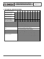
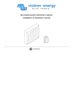
User’s Guide
Shop online at
omega.com
e-mail: [email protected]
For latest product manuals:
omegamanual.info
FDT100 Series
Ultrasonic Flow Meters
OMEGAnet ® Online Service
omega.com
Internet e-mail
[email protected]
Servicing North America:
U.S.A.:
One Omega Drive, P.O. Box 4047
Stamford, CT 06907-0047
TEL: (203) 359-1660
FAX: (203) 359-7700
e-mail: [email protected]
Canada:
976 Bergar
Laval (Quebec) H7L 5A1, Canada
TEL: (514) 856-6928
FAX: (514) 856-6886
e-mail: [email protected]
ISO 9001 Certified
For immediate technical or application assistance:
U.S.A. and Canada: Sales Service: 1-800-826-6342/1-800-TC-OMEGA® Customer
Service: 1-800-622-2378/1-800-622-BEST® Engineering
Service: 1-800-872-9436/1-800-USA-WHEN®
Mexico:
En Español: (001) 203-359-7803
e-mail: [email protected]
FAX: (001) 203-359-7807
[email protected]
Servicing Europe:
Czech Republic:
Frystatska 184, 733 01 Karviná , Czech Republic
TEL: +420 (0)59 6311899
FAX: +420 (0)59 6311114
Toll Free: 0800-1-66342
e-mail: [email protected]
Germany/Austria: Daimlerstrasse 26, D-75392 Deckenpfronn, Germany
TEL: +49 (0)7056 9398-0
FAX: +49 (0)7056 9398-29
Toll Free in Germany: 0800 639 7678
e-mail: [email protected]
United Kingdom:
ISO 9002 Certified
One Omega Drive, River Bend Technology Centre
Northbank, Irlam, Manchester
M44 5BD United Kingdom
TEL: +44 (0)161 777 6611
FAX: +44 (0)161 777 6622
Toll Free in United Kingdom: 0800-488-488
e-mail: [email protected]
It is the policy of OMEGA Engineering, Inc. to comply with all worldwide safety and EMC/EMI
regulations that apply. OMEGA is constantly pursuing certification of its products to the European New
Approach Directives. OMEGA will add the CE mark to every appropriate device upon certification.
The information contained in this document is believed to be correct, but OMEGA accepts no liability for any errors it
contains, and reserves the right to alter specifications without notice.
WARNING: These products are not designed for use in, and should not be used for, human applications.
Design, Assembly and Service Manual
Ultrasonic water meter FDT100 series
Page 1 of 20
Contents
1.
APPLICATION...................................................................................................................................................2
2.
MEASUREMENT METHOD ..............................................................................................................................2
3.
TECHNICAL DESCRIPTION ............................................................................................................................2
3.1. Meter characteristics.................................................................................................................................................... 2
3.2. Meter design................................................................................................................................................................... 3
3.2.1.
Compact version – basic dimensions .................................................................................................................. 3
3.2.2.
Remote version – basic dimensions .................................................................................................................... 3
3.2.3.
Ultrasonic sensor unit ............................................................................................................................................ 4
3.2.4.
Electronic unit.......................................................................................................................................................... 4
3.2.5.
Separate sensor unit – terminal board ................................................................................................................ 6
3.2.6.
Meter handling ........................................................................................................................................................ 7
4.
TECHNICAL SPECIFICATIONS.......................................................................................................................8
5.
PROJECT DESIGN AND METER INSTALLATION .........................................................................................9
5.1. Project design of systems including ultrasonic water meters.......................................................................... 9
5.2. Meter installation......................................................................................................................................................... 12
5.2.1.
General recommendations.................................................................................................................................. 12
5.2.2.
Mechanical fitting.................................................................................................................................................. 13
5.2.3.
Electrical connections .......................................................................................................................................... 13
5.2.4.
Seals on meters.................................................................................................................................................... 15
6.
OPERATIONAL START..................................................................................................................................17
7.
OPERATION....................................................................................................................................................18
7.1. Reading the measured quantities from the meter display ............................................................................... 18
7.2. Electrical outputs ........................................................................................................................................................ 18
7.2.1.
Pulse output .......................................................................................................................................................... 18
7.2.2.
Current output ....................................................................................................................................................... 19
7.3. Error identification function ..................................................................................................................................... 19
7.4. Battery life and replacement .................................................................................................................................... 19
8.
CALIBRATION ................................................................................................................................................20
Design, Assembly and Service Manual
Ultrasonic water meter FDT100 series
Page 2 of 20
1. APPLICATION
Battery-powered ultrasonic water meters of the FDT100 SERIES type series are intended for technological
measurements of instantaneous flow rate and consumption in water-supply networks, and archiving of the measured
data. Measurement of water pressure in piping is also possible. The technical capabilities including high measurement
accuracy and long-term stability over a wide range of measured values make it possible to use the meters, apart from
the conventional measurements, for monitoring leakage and the general condition of water supply networks. The
FDT100 SERIES water meters do not require external power, do not include any moving parts or filters to prevent
choking with mechanical impurities and, compared to conventional water meters, have significantly lower hydraulic
losses.. Flow meters shall be used in standard non-explosive environments.
Any installation of flow meter must be in conformity with technical conditions mentioned in this manual.
2. MEASUREMENT METHOD
The measurement method used is a single-beam pulse transit-time method based on determination of the time
needed for an ultrasonic pulse wave to cross the distance between two probes embedded in piping. Each of the probes
functions as the sender and receiver in turns so that the ultrasonic wave travels in turns in and against the water flow
direction. This arrangement allows for effective elimination of errors due to asymmetry in the probe locations.
3. TECHNICAL DESCRIPTION
3.1. Meter characteristics
The FDT100 SERIES ultrasonic water meter is an electronic device used to measure the water flow rate in a fully
flooded piping. It is manufactured and supplied in two versions: compact and remote. The compact version, designated
FDT100 .SERIES , has the electronic unit attached directly onto the flow sensor housing. The remote version,
designated FDT100-R .SERIES, has the electronic unit separated from the sensor and connected with it by means of a
cable ( length 6m). The electronic unit is accommodated in a separate box that can be fitted on a wall.
In the standard configuration, the meter software allows for measuring and display of the instantaneous flow rate
and total volume of water passed through the meter since the volume counter was last reset. The meter is provided
with a passive pulse output including an optocoupler. The pulse length is 40ms. The meter include passive current
output. The meter is supplied suitable for use in drinking-water supply systems.
Design, Assembly and Service Manual
Page 3 of 20
Ultrasonic water meter FDT100 series
3.2. Meter design
5,35"(136mm)
ELECTRONIC
CONTROL UNIT
ULTRASONIC
SENSOR
S/N 22686/06
2"
BN 15
1,45psi
232
PRESSURE
DN
S
ANSI
psi
D
G/imp
IMPULSE OUTPUT CONST. 5
CURRENT OUTPUT
4-20 mA
warranty
void if
removed
L
3.2.1.
Compact version – basic dimensions
DN
L [inch] / [mm]
S [inch] / [mm]
D [inch] / [mm]
Weight [lb] / [kg]
2" (50)
11.8/300
8.2/208
6.5/165
22/10
2½" (65)
11.8/300
8.9/225
7.3/185
24/11
3" (80)
13.8/350
9.3/237
7.9/200
33/15
4" (100)
13.8/350
10/253
8.7/220
39/17.5
5" (125)
13.8/350
11/280
9.8/250
50/22.5
6" (150)
13.8/350
12/307
11.2/285
57/26
Remote version – basic dimensions
3,54"(90mm)
ELECTRONIC
SENSOR
0,4"(10mm)
2,4"(61mm)
1)
max. length 5m
3,15"(80mm)
TERMINAL BOARD
ULTRASONIC
SENSOR
S/N 22686/06
BN 15
PRESSURE
1,45psi
232
psi
G/imp
IMPULSE OUTPUT CONST. 5
CURRENT OUTPUT
4-20 mA
warranty
void if
removed
D
ANSI 2"
1)
"(6
0,15"(4mm)
m
11m
3"(
0,4
"(6
2, 4
3,3"(84mm)
, 5m
m)
2,4
0, 2
2"(5
5,35"(136mm)
3.2.2.
1¼" (32) 1½" (40)
10.2/260 11.8/300
7.5/190 7.8/198
5.5/140 5.9/150
10/4.5
15/7
)
8" (200)
13.8/350
14/352
13.4/340
80/36.5
Design, Assembly and Service Manual
Ultrasonic water meter FDT100 series
DN
L [inch] / [mm]
D [inch] / [mm]
Weight [lb] / [kg]
1¼" (32) 1½" (40)
10.2/260 11.8/300
5.5/140 5.9/150
11/5
16.5/7.5
2" (50)
11.8/300
6.5/165
23/10.5
3.2.3.
Ultrasonic sensor unit
2½" (65)
11.8/300
7.3/185
25/11.5
3" (80) 4" (100) 5" (125)
13.8/350 13.8/350 13.8/350
7.9/200 8.7/220 9.8/250
34/15.5 40/18
51/23
Page 4 of 20
6" (150) 8" (200)
13.8/350 13.8/350
11.2/285 13.4/340
58/26.5 82/37
The ultrasonic sensor unit comprises a housing made of ductile cast iron (material according to DIN GGG40) with
two flanges (according to 150# ANSI B) and two embedded ultrasonic probes. The sensor housing is painted with
surface finish of KOMAXIT E 2110 blue powder epoxy paint (RAL 5017). The rating plate attached to the sensor body
includes the basic meter specifications including the sensor size (DN), the accuracy class (B) and the rated constant
flow rate in gallons per minute (qP, the figure next to N) – see the picture below.
ULTRASONIC PROBE
LABEL SENSOR
ANSI 2"
S/N 22686/06
BN 15
PRESSURE
1,45psi
232
psi
IMPULSE OUTPUT CONST. 5 G/imp
CURRENT OUTPUT
4-20 mA
warranty
void if
removed
3.2.4.
Electronic unit
The electronic unit and battery are placed in an aluminium box with a plastic lid. The box is provided with a special
valve preventing moisture condensation inside the box and up to three grummets for cables of circular cross-section.
The surface finish is by paint of orange hue (RAL 1017).
Two M8 grummets are intended for cables of outside diameter 3.5 to 5mm to be connected to the selected output
signal terminals. On delivery, these grummets are blinded. The third grummet (M12) is provided only in the case of the
remote meter version and is intended for the cable of diameter 6.5 to 8mm connecting the sensor and the remote
electronic unit. The connecting cable is supplied attached to the electronic unit with the other end ready to be
connected to the sensor terminal board.
The meter display is located under the transparent plastic cover. The push-button on the unit box is used to select
the desired display mode: either instantaneous flow rate (in gallons per minute GPM or m3/hour), the total fluid volume
(in thousands of gallons or m3) passed through the meter sensor since the volume counter was last reset, or the fluid
pressure (in bar). The actual quantity displayed is indicated at the bottom line by the symbol j. In the case of a meter
failure, the respective error message (E1 through to E5) will be indicated by the same symbol j - see the picture
below. A recess in the unit box is for an optical probe to be applied onto the recessed surface to read the stored data.
Also found under the box lid is the meter rating plate:
Design, Assembly and Service Manual
Ultrasonic water meter FDT100 series
Page 5 of 20
Plate including rated parameters in G.103 a GPM
ALUMINIUM
HOUSING
CONDENSATION
VALVE
DISPLAY
OMEGA
E1 E2
E3 E4 E5
FDT 103 XA
R
3
G.10 GPM
IP 67 DC 3,6V
T 32...122°F
BATTERY
BUSHINGS
RECESS FOR
OPTICAL PROBE
PUSH-BUTTON
PLASTIC
COVER
Plate including rated parameters in m3 and m3/hour
ALUMINIUM
HOUSING
CONDENSATION
VALVE
DISPLAY
OMEGA
E1 E2 E3 E4 E5
FDT 103 XA
3
R
3
m m/h
IP 67 DC 3,6V
T 32...122°F
BATTERY
BUSHINGS
RECESS FOR
OPTICAL PROBE
PUSH-BUTTON
PLASTIC
COVER
IMPORTANT NOTICE: Prior to operational start, check proper tightening of the grummets and blinding of the
unused ones.
Design, Assembly and Service Manual
Ultrasonic water meter FDT100 series
3.2.5.
Page 6 of 20
Separate sensor unit – terminal board
In the case of the remote version of the FDT100 SERIES water meter, attached to the sensor housing is a terminal
board in an aluminium box with a sealed lid. The terminal box is provided with a M12 grommet for a cable of diameter
6.5 to 8mm, a valve preventing moisture condensation inside the box and four spring-loaded WAGO terminals to which
the ultrasonic probes signals are brought. Connected to these terminals are the wires of the cable leading to the remote
electronic unit.
BUSHING
CONNECTING CABLE
TO ELECTRONIC UNIT
WAGO TERMINALS
X2
4
3
2
1
X1
4
CONDENSATION
VALVE
3
2
1
ALUMINIUM
BOX
BOX
LID
Design, Assembly and Service Manual
Page 7 of 20
Ultrasonic water meter FDT100 series
3.2.6.
Meter handling
The arrows indicate incorrect grips on the meter assembly. Do not lift the meter holding it by the electronic unit or
the protection tubes – see the figure.
ANSI
2"
S/N 22686/06
BN 15
PRESSURE
ANSI
2"
1,45psi
232
S/N 22686/06
BN 15
psi
PRESSURE
G/imp
IMPULSE OUTPUT CONST. 5
CURRENT OUTPUT
4-20 mA
1,45psi
232
psi
G/imp
IMPULSE OUTPUT CONST. 5
CURRENT OUTPUT
4-20 mA
warranty
void if
removed
warranty
void if
removed
The arrows indicate the correct grips on the meter assembly. To lift the meter, hold it by the flanges or meter body.
ANSI 2"
S/N 22686/06
BN 15
PRESSURE
1,45psi
232
psi
IMPULSE OUTPUT CONST. 5 G/imp
CURRENT OUTPUT
4-20 mA
warranty
void if
removed
Design, Assembly and Service Manual
Ultrasonic water meter FDT100 series
Page 8 of 20
4. TECHNICAL SPECIFICATIONS
Rated internal diameter DN
Overloading flow rate qs
Continuous flow rate qp
Transient flow rate qt
Minimum flow rate qmin
Pulse output constant k i
Rated pressure РN
16
Accuracy class
Temperature of measured fluid
Ambient temperature
Display unit
Power
Protection class
Pressure loss
Outputs
GPM
m3/h
GPM
m3/h
GPM
m3/h
GPM
m3/h
G/imp
l/imp
1¼"
(32)
52
12
26
6
2.1
0.48
0.52
0.12
2
10
1½"
(40)
90
20
45
10
3.5
0.8
0.9
0.2
5
25
2"
(50)
130
30
65
15
13.2
3
2
0.45
5
25
2½"
(65)
220
50
110
25
22
5
3.3
0.75
10
50
3"
(80)
350
80
175
40
35
8
5.3
1.2
10
50
4"
5"
(100) (125)
530
880
120
200
265
440
60
100
53
88
12
20
7.9
13.2
1.8
3
15
30
100
100
6"
8"
(150) (200)
1,320 1,585
300
360
660 1,100
150
250
132
220
30
50
19.8
33
4.5
7.5
30
30
100
100
+/- 2% of reading, +/- 5 % below minimum transition rate
32 to 122°F (0 to 50°С)
32 to 122°F (0 to 50°С)
single-line 8-character LC display
Li battery 3.6V/3.6Ah, type LSH 14 light lifetime 1 year from the day
of production (standard "transport" battery)
Li battery 3.6V/16Ah, type LS 33600, minimum lifetime 6 to 8 years
since a date of production ( customer supplied)
IP 67
less than 0.1 bar at qp
passive pulse U = 5 to 30V, Imax = 10mA, pulse length 40ms
passive current output 4 to 20mA, Umax = 24V
Optional accessories
remote meter version, maximum cable length 5m (-R)
Design, Assembly and Service Manual
Page 9 of 20
Ultrasonic water meter FDT100 series
5. PROJECT DESIGN AND METER INSTALLATION
Compliance with standards ISO 4064-1, ISO 4064-2 and strict observance of the recommendations in this Manual
are required in all project-design work regarding application and installation of the FDT100 SERIES ultrasonic water
meters in water-supply networks.
.
5.1. Project design of systems including ultrasonic water meters
In water supply and distribution systems, water meters should be located so as to ensure maximum measurement
accuracy. In the case of the FDT100 SERIES meters, the lengths of the required straight piping sections on the input
5 DN
3 DN
DN 80
PN16
BN40
0,1
5 DN
3 DN
ser.no
bar
Meter constant
50
Current output
4÷20
mA
Pressure range
1÷10
bar
l/imp.
DN 80
PN16
BN40
FLOW DIRECTION
0,1
ser.no
bar
Meter constant
50
Current output
4÷20
mA
Pressure range
1÷10
bar
l/imp.
FLOW DIRECTION
and output sides are at least 5xDN and 3xDN, respectively.
Minimum lengths of straight piping sections
If there is any pump nearby, it should be located on the output side of the meter at the distance of at least 20xDN.
20 DN
DN 80
PN16
BN40
0,1
v.è.
barù
Konstanta mì øidla 50l/imp.
Proudový výstup 4-20mA
:
FLOW DIRECTION
Pump placement
In cases where full flooding of the piping cannot be guaranteed at all times, the meter sensor should be fitted in
such piping section where these conditions will always be met.
Design, Assembly and Service Manual
Page 10 of 20
Ultrasonic water meter FDT100 series
3
5
DN
v.
DN
è.
DN
5 DN
3 DN
rù
ba
p.
16 1
m
l/i
PN
0,
50
A
m
la
40
20
ì øid
BN
4-:
m
a
up
nt
st
ta
vý
ns
vý
Ko
do
ou
Pr
80
FL
OW
D
E
IR
CT
IO
N
DN 80
PN16
BN40
0,1
v.è.
barù
Konstanta mì øidla 50l/imp.
Proudový výstup 4-20mA
:
FLOW DIRECTION
Meter placement to ensure full flooding
FLOW DIRECTION
v.è.
barù
0,1
BN40
PN16
DN 80
Proudový výstup 4-20mA
:
Konstanta mì øidla 50l/imp.
Should the meter need be installed in a vertical piping section, the water flow direction shall be upwards.
Vertical sensor position
Design, Assembly and Service Manual
Page 11 of 20
Ultrasonic water meter FDT100 series
To ensure reliable and accurate measurements under all circumstances, the measured fluid shall fill the internal
cavity of the sensor at all times. Therefore the sensor should not be placed at the highest piping section or in a
vertical piping section where the flow direction is downwards, in particular in cases where a piping outlet to open
tanks is anywhere near.
DN 80
PN16
BN40
0,1
v.è.
barù
DN 80
0,1
PN16
BN40
barù
v.è.
Konstanta mì øidla 50l/imp.
FLOW DIRECTION
:
Proudový výstup 4-20mA
FLOW DIRECTION
Konstanta mì øidla 50l/imp.
Proudový výstup 4-20mA
:
Examples of incorrect sensor placement
There are no limitations regarding sensor position in piping; however, consideration should be given to the ease of
reading the display data and access to the optical probe contact point (see the picture below).
360°
The above recommendations regarding the meter/sensor placement and installation apply to both the compact and
remote meter versions.
Design, Assembly and Service Manual
Ultrasonic water meter FDT100 series
Page 12 of 20
5.2. Meter installation
5.2.1.
General recommendations
In the basic arrangement (flow direction from left to right and the sensor installed into a horizontal piping section),
the electronic unit is fitted onto the sensor body as shown in the following picture.
OMEGA
E1 E2 E3 E4 E5
FDT 103 XA
R
G.103 GPM
IP 67 DC 3,6V
T 32...122°F
FLOW DIRECTION
In the case of vertical mounting, or the flow direction from right to left, the electronic unit can be rotated with respect
to the sensor body by 90 or 180° in both ways; 180° rotation is a limit to avoid straining the connecting wires. The unit
can be rotated upon loosening the arresting screw M5 at the unit base using an Alien wrench, size 2.5mm. The 90°
positions on the unit base are marked by recesses for the arresting screw..
18
0°
18
0°
OMEGA
E1 E2 E3 E4 E5
FDT 103 XA
VIEW P
R
3
G.10 GPM
IP 67 DC 3,6V
T 32...122°F
P
lock screw
FLOW DIRECTION
To prevent signal interference, the meter wiring shall be placed at least 25cm away from any live power cables.
Design, Assembly and Service Manual
Ultrasonic water meter FDT100 series
Page 13 of 20
The interconnection between the meter sensor and electronic unit (the remote meter version) is made by a shielded
cable with the shielding connected to the earth potential at the sensor terminal board. It is recommended that all output
signals (the pulse and current outputs) be connected using shielded cables with the shielding connected to the earth
potential on the side of the plant control system. The meter sensor shall also be carefully grounded. To do that, connect
the grounding bolt on the sensor flange with the piping flanges using an grounding conductor of cross-section of at
least 4mm2 .
2
min 4mm -green and yellow wire insulation
OMEGA
R
3
G.10 GPM
FDT 103 XA
5.2.2.
IP 67 DC 3,6V
T 32...122°F
Mechanical fitting
The ultrasonic sensor shall be fitted into the water piping across piping flanges matching the meter flanges ANSI.
5.2.3.
Electrical connections
The compact meter version (FDT100 SERIES): the electrical interconnection operation consists of connecting the
output signal cables to the respective terminals on terminal board in the electronic unit. The terminal board can be
accessed upon removal of the plastic lid at the top of the unit box. The lid is secured in position by means of two M4
screws with hexagonal socket heads for Alien wrench size 2mm.
At the bottom side of the plastic lid there are two slots 8mm wide where a flat tool can be inserted to help lift the lid
from the box. It is recommended to insert a screwdriver into one of the slots and slightly pry upwards. The locations of
the slots are shown in the picture below. Prior to replacing the lid, apply a thin layer of glycerine or silicon oil on the
sealing O-ring.
When replacing the lid, the 3mm hole at the bottom side of the plastic lid should be fitted onto the guide pin of
diameter 2.5mm press-fitted at the box bottom.
Design, Assembly and Service Manual
Page 14 of 20
Ultrasonic water meter FDT100 series
nty
rra if
waoid oved
v m
re
X2
X1
RX
TX
-I
+I
-IMP
+IMP
-RS
+RS
1 2 3 4 5 6 7 8 9
OUTPUT TERMINAL
BOARD CONNECTIONS
9
Impulse output
(external power supply)
Current otput
(external power supply)
8
Communication
interface RS 232
y
nt
ra if ed
v
ar
w oidmo
v e
r
FDT 100 series
X1
3
4
5
6
7
1-30k
Not used
I=4-20 mA
-IMP
+
Current output power supply U=10-24V
Impulse output
(exter.power supply) +IMP
+ U=5-25V
- Imax.=10mA
-I
interface RS 232
2
Current otput
(exter.power supply) +I
Communication
1
-RS
+RS
RX
TX
Impulse output
power supply
The remote meter version (FDT100 SERIES ): the free end of the signal cable from the electronic unit is to be
connected to the respective spring-loaded WAGO terminals at terminal board in the sensor unit assembly. The lid on
the terminal box is held in position by means of four M4 screws with hexagonal socket heads for Alien wrench size
3mm.
The output signal cable connections the terminal board are made in the same way as shown above for the case
of the compact meter version.
Design, Assembly and Service Manual
Ultrasonic water meter FDT100 series
P
Page 15 of 20
VIEW P
of the electronic unit with the top cover removed
nty
rra
waoid ifoved
v em
r
X2
X1
-RS
+RS
RX
TX
-I
+I
-IMP
+IMP
1 2 3 4 5 6 7 8 9
brown
X2
Current otput
(external power supply)
Impulse output
(external power supply)
Communication
interface RS 232
y
nt
ra f d
ar i ve
w oidmo
v re
white
4
3
2 1
X1
4
3
2
1
CONNECTIONS BETWEEN ELECTRONIC UNIT AND FLOW SENSOR
FDT 100
series
AUXILIARY ELECTRONIC UNIT
PROBE 1
PROBE 2
brown
white
X2 4
3
PROBE 2
4
3
2
1
PROBE 1
2
1
X1
FLOW SENSOR TERMINAL BOARD
5.2.4.
Seals on meters
The water meters used as technological meters shall be provided with clamp-on and stick-on company and
assembly seals as shown in the following illustration pictures.
The compact meter version, type FDT100 SERIES
Design, Assembly and Service Manual
Ultrasonic water meter FDT100 series
R
Page 16 of 20
Clasp-on seals
P
ANSI
2"
S/N 22686/06
BN 15
PRESSURE
1,45psi
232
psi
G/imp
IMPULSE OUTPUT CONST. 5
CURRENT OUTPUT
4-20 mA
warranty
void if
removed
VIEW R
Stick-on seals
( with top cover removed)
Stick-on assembly seal
on terminal board cover
X2
y
nt
rra f
waoid ioved
v em
r
VIEW P
X1
The remote meter version, type FDT100 SERIES
-IMP
+IMP
RX
TX
-I
+I
-RS
y
nt
ra if ed
v
ar
w oidmo
v e
r
+RS
1 2 3 4 5 6 7 8 9
Design, Assembly and Service Manual
Page 17 of 20
Ultrasonic water meter FDT100 series
FLOW SENSOR
Clasp-on assembly seals
on connecting cable housing
Clasp-on seal
Clasp-on seal
ANSI
2"
S/N 22686/06
BN 15
PRESSURE
1,45psi
232
psi
G/imp
IMPULSE OUTPUT CONST. 5
CURRENT OUTPUT
4-20 mA
warranty
void if
removed
VIEW R
Stick-on seals
DATA-PROCESSING ELECTRONIC UNIT
( with top cover removed)
R
nt y
rra if d
waoid o
ve
v em
r
X2
X1
-IMP
+IMP
-RS
+RS
TX
-I
+I
RX
1 2 3 4 5 6 7 8 9
y
nt
ra if ed
v
ar
w oidmo
ve
r
Stick-on assembly seal
on terminal board cover
6. OPERATIONAL START
The water meter is delivered calibrated and in a fully operative condition. Once it is fitted into the selected metering
point in the piping, bled and filled with the technological fluid, it is ready for operation. The condition of readiness to start
is indicated by disappearance of the error messages j at the bottom of the meter display unit. Using the control pushbutton, check the selection of measurement modes: the instantaneous flow rate, total volume passed and pressure (if
applicable).
Design, Assembly and Service Manual
Page 18 of 20
Ultrasonic water meter FDT100 series
7. OPERATION
7.1. Reading the measured quantities from the meter display
The eight-character display unit can show either the instantaneous flow rate in gallons per minute (or m3/hour), the
total volume of the fluid passed through the meter sensor since the reading was last reset, in G.103 (or m3). The
reading of instantaneous flow rate has a certain delay as the displayed value is determined as the arithmetic average of
the six latest measurements (each taken in 1-second intervals). So calculated values also appear at the meter outputs.
The delay becomes noticeable in the cases of rapidly changing (growing or falling) flow rate. Meter errors will be
indicated on the display. Due to the limited power capacity of the meter, the various display modes can only be
selected in intervals of 1 second or longer. It is therefore recommended that the display mode selection push-button be
always depressed for at least one second, and the next selection command be given after another 1 second or longer.
Depending on the reading of the total fluid volume passed, the decimal point on the display will move as shown in the
following picture.
3
3
Displayed data in G.10 (m )
Decimal point position for
total volume less than
3
Decimal point position for
total volume greater than
3
100,000 G.10 (m )
10,000,000 G.10 (m )
Decimal point position for
total volume between
3
3
3
3
100,000 G.10 (m ) and 1,000,000 G.10 (m )
Decimal point position for
total volume between
3
3
3
3
1,000,000 G.10 ( m ) and 10,000,000 G.10 ( m )
3
3
7.2. Electrical outputs
7.2.1.
Pulse output
An pulse output is found on all FDT100 SERIES water meters irrespective of their version or configuration. In
includes an optocoupler connected to terminals 7 and 8 (terminal board X1); the permitted current loading is 10mA, the
pulse length 40ms. On a customer’s request the pulse length can be set at 2ms. If voltage pulses are required, use an
external power source of 5 to 25V DC connected in series with a limiting resistor so that the maximum current would
not exceed 10mA. The interconnection of external power source and limiting resistor is shown in the picture illustrating
the interconnections at the output terminal board (Section 5.2.3 above).
The pulse length can also be modified on site; for 40ms pulses, use jumper J5 to connect terminals J5:2 and J5:3
(X1), for 2ms pulses, connect terminals J5:1 and J5:2 (see the figure below).
J5
1 2 3
1
2
3
4
5
X1
6
7
8
9
Design, Assembly and Service Manual
Ultrasonic water meter FDT100 series
7.2.2.
Page 19 of 20
Current output
The current output 4 - 20mA is connected to terminals 5 and 6 at the output terminal board. Upon attaining the
output current level of 20mA (corresponding to Qmax), the current will not exceed this value and the error message E4
will appear on the display (see Section 7.5. below). To utilize the output current function, use an external power source
of 10 to 24V DC and the interconnection at the output terminal board as described in Section 5.2.3. The maximum
permitted resistance (the ohm resistance of the cable + input resistance of the co-operating equipment) of the current
output circuit shall be determined using the following formula:
Rs [Ω] =
U source [V] - 7
0.02
.
7.3. Error identification function
Meter errors shall be identified as E1 through to E5 by symbol j shown at the bottom of the display unit.
Error identification symbols:
E1 - the ultrasonic signal cannot freely propagate in the sensor cavity (due to the
presence of air or mechanical particles)
E2 - too great a difference between the signal travel times in and against the fluid
flow direction (possibly due to the presence of air at one of the probes, which
may be a temporary condition during the operation of filling the piping with
fluid, or due to contamination of the face part of one of the probes)
E3 - A/D converter error (e.g. due to strong interference)
E4 - flow rate in excess of qs
E5 - flat meter battery
Should the display go completely blank, check the battery condition (the voltage should be over 3V). Replace
defective battery using the procedure described in Section 7.6. Should the battery replacement fail to restore the
correct meter function, send the meter for repair to the manufacturer’s service centre.
7.4. Battery life and replacement
Electronic unit is equipped with battery SAFT LITHIUM 3,6V /3,6Ah LSH 14 "light" (size C) containing less than 1g
of lithium and is equipped with plastic case capable of using of either C and D size battery. Lifetime of LSH 14 "lite"
battery is 1 year since date of production and can be replaced by battery LITHIUM 3.6V / 16Ah LS 33600 (size D) with
lifetime up to 8 years, with using of communication functions up to 6 years. Plastic case is not used for D size battery
LSH 14 "light" battery is used as a "transport battery," because it is non-restricted to transport/non-assigned to Class
9 according Lithium battery transport regulation (Ref. TC-LSH 14"light"-09/03-1).
To replace the meter battery, first remove the plastic lid on the electronic unit box held in position by two M4 screws
with hexagonal socket heads (use Alien wrench, size 2mm), see Section 5.2.3., then loosen three M3 screws holding
the electronic module in the aluminium box and pull the module outside the box. While doing that, make sure you do
not damage any metrological or company seals. The electronic module can only be removed as far as probe
conductors and output signal cables permit. The battery is located in a holder at the bottom of the unit; pull the battery
free and replace it with a new one. Mind the correct polarity as indicated on a plate on the battery holder. Push the
electronic module back into the box, tighten the holding bolts, replace the box lid, fix its position with screw and apply
assembly seal on one of them.
Design, Assembly and Service Manual
Page 20 of 20
Ultrasonic water meter FDT100 series
BATTERY HOLDER
PLATE SHOWING
BATTERY POLARITY
nty
rra f
wa id i ved
voemo
r
BATTERY
DIRECTION OF REMOVING
BATTERRY FROM HOLDER
MOUNTING SCREWS M3
ELECTRONIC UNIT ASSEMBLY
y
nt
ra f d
ar i ve
w oidmo
v e
r
STICK-ON SEALS
The electronic module removed from its box
8. CALIBRATION
The standard calibration is done with respect to the pulse output. In that case the measurement error at the current
output will be approx. 1% higher than that at the pulse output. If the customer requires calibration for the current output,
it can be done and the additional error of about 1% will then appear at the pulse output.
WARRANTY/DISCLAIMER
OMEGA ENGINEERING, INC. warrants this unit to be free of defects in materials and workmanship for a
period of 13 months from date of purchase. OMEGA’s WARRANTY adds an additional one (1) month
grace period to the normal one (1) year product warranty to cover handling and shipping time. This
ensures that OMEGA’s customers receive maximum coverage on each product.
If the unit malfunctions, it must be returned to the factory for evaluation. OMEGA’s Customer Service
Department will issue an Authorized Return (AR) number immediately upon phone or written request. Upon
examination by OMEGA, if the unit is found to be defective, it will be repaired or replaced at no charge.
OMEGA’s WARRANTY does not apply to defects resulting from any action of the purchaser, including
but not limited to mishandling, improper interfacing, operation outside of design limits, improper repair,
or unauthorized modification. This WARRANTY is VOID if the unit shows evidence of having been tampered
with or shows evidence of having been damaged as a result of excessive corrosion;
or current, heat, moisture or vibration; improper specification; misapplication; misuse or other operating
conditions outside of OMEGA’s control. Components in which wear is not warranted, include but are not
limited to contact points, fuses, and triacs.
OMEGA is pleased to offer suggestions on the use of its various products. However,
OMEGA neither assumes responsibility for any omissions or errors nor assumes liability for any
damages that result from the use of its products in accordance with information provided by
OMEGA, either verbal or written. OMEGA warrants only that the parts manufactured by the
company will be as specified and free of defects. OMEGA MAKES NO OTHER WARRANTIES OR
REPRESENTATIONS OF ANY KIND WHATSOEVER, EXPRESSED OR IMPLIED, EXCEPT THAT
OF TITLE, AND ALL IMPLIED WARRANTIES INCLUDING ANY WARRANTY OF
MERCHANTABILITY AND FITNESS FOR A PARTICULAR PURPOSE ARE HEREBY
DISCLAIMED. LIMITATION OF LIABILITY: The remedies of purchaser set forth herein are
exclusive, and the total liability of
OMEGA with respect to this order, whether based on contract, warranty, negligence,
indemnification, strict liability or otherwise, shall not exceed the purchase price of the
component upon which liability is based. In no event shall OMEGA be liable for
consequential, incidental or special damages.
CONDITIONS: Equipment sold by OMEGA is not intended to be used, nor shall it be used: (1) as a “Basic
Component” under 10 CFR 21 (NRC), used in or with any nuclear installation or activity; or (2) in medical
applications or used on humans. Should any Product(s) be used in or with any nuclear installation or
activity, medical application, used on humans, or misused in any way, OMEGA assumes no responsibility
as set forth in our basic WARRANTY/DISCLAIMER language, and, additionally, purchaser will indemnify
OMEGA and hold OMEGA harmless from any liability or damage whatsoever arising out of the use of the
Product(s) in such a manner.
RETURN REQUESTS/INQUIRIES
Direct all warranty and repair requests/inquiries to the OMEGA Customer Service Department. BEFORE
RETURNING ANY PRODUCT(S) TO OMEGA, PURCHASER MUST OBTAIN AN AUTHORIZED RETUR
(AR) NUMBER FROM OMEGA’S CUSTOMER SERVICE DEPARTMENT (IN ORDER TO
AVOID PROCESSING DELAYS). The assigned AR number should then be marked on the outside of the
return package and on any correspondence.
The purchaser is responsible for shipping charges, freight, insurance and proper packaging to prevent breakag
FOR WARRANTY RETURNS, please have the
FOR NON-WARRANTY REPAIRS, consult OMEGA
following information available BEFORE
for current repair charges. Have the following
contacting OMEGA:
information available BEFORE contacting OMEGA:
1. Purchase Order number under which the product was 1. Purchase Order number to cover the COST
PURCHASED,
of the repair,
2. Model and serial number of the product under
2. Model and serial number of the product, and
warranty, and
3. Repair instructions and/or specific problems
3. Repair instructions and/or specific problems
relative to the product.
relative to the product.
OMEGA’s policy is to make running changes, not model changes, whenever an improvement is possible. This affords
our customers the latest in technology and engineering.
OMEGA is a registered trademark of OMEGA ENGINEERING, INC.
© Copyright 2005 OMEGA ENGINEERING, INC. All rights reserved. This document may not be copied, photocopied,
reproduced, translated, or reduced to any electronic medium or machine-readable form, in whole or in part, without the prior
written consent of OMEGA ENGINEERING, INC.
Where Do I Find Everything I Need for
Process Measurement and Control?
OMEGA…Of Course!
Shop online at omega.com
TEMPERATURE
Thermocouple, RTD & Thermistor Probes, Connectors, Panels & Assemblies
Wire: Thermocouple, RTD & Thermistor
Calibrators & Ice Point References
Recorders, Controllers & Process Monitors
Infrared Pyrometers
PRESSURE, STRAIN AND FORCE
Transducers & Strain Gages
Load Cells & Pressure Gages
Displacement Transducers
Instrumentation & Accessories
FLOW/LEVEL
Rotameters, Gas Mass Flowmeters & Flow Computers
Air Velocity Indicators
Turbine/Paddlewheel Systems
Totalizers & Batch Controllers
pH/CONDUCTIVITY
pH Electrodes, Testers & Accessories
Benchtop/Laboratory Meters
Controllers, Calibrators, Simulators & Pumps
Industrial pH & Conductivity Equipment
DATA ACQUISITION
Data Acquisition & Engineering Software
Communications-Based Acquisition Systems
Plug-in Cards for Apple, IBM & Compatibles
Datalogging Systems
Recorders, Printers & Plotters
HEATERS
Heating Cable
Cartridge & Strip Heaters
Immersion & Band Heaters
Flexible Heaters
Laboratory Heaters
ENVIRONMENTAL
MONITORING AND CONTROL
Metering & Control Instrumentation
Refractometers
Pumps & Tubing
Air, Soil & Water Monitors
Industrial Water & Wastewater Treatment
M-4268/0406