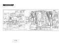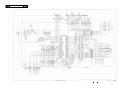
1
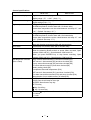
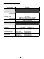
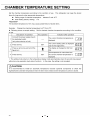
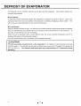
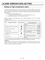
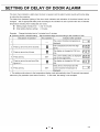
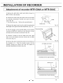
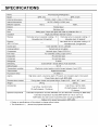
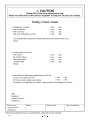
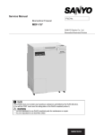
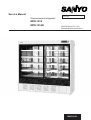
Service Manual
Pharmaceutical refrigerator
MPR-1014
MPR-1014R
FILE No.
SANYO Electric Co., Ltd.
Biomedical Business Division
SM9910182
Effective models
This service manual is effective following models.
Model name
MPR-1014
MPR-1014R
Product code
823 622 51
823 622 52
823 622 53
823 622 54
823 622 56
823 622 57
823 622 71
823 622 72
823 622 73
823 622 74
823 622 76
823 622 77
Voltage and Frequency
115V
60Hz
220V
50Hz
220V
60Hz
220/230/240V
50Hz
220V
50Hz
110V
60Hz
115V
60Hz
220V
50Hz
220V
60Hz
220/230/240V
50Hz
220V
50Hz
110V
60Hz
Contents
㩷 㩷 㩷 㩷 㩷 㩷 㩷 㩷
Page
Specifications
--------------------------------------------
1
䋭Structural specifications
䋭Control specifications
䋭Performance specifications
Dimensions
----------------------------------------------
4
Cooling unit parts
----------------------------------------------
5
Cooling circuits
------------------------------------------------
6
Components on PCB
------------------------------------------------
7
Connections on PCB
------------------------------------------------
8
Wiring diagram
-------------------------------------------------
9
Circuit diagram
---------------------------------------------
10
Control specifications
---------------------------------------------
11
Electric parts
---------------------------------------------
26
Specifications of sensor
---------------------------------------------
27
Mounting of compressor terminal cover
------------------------
28
Parts layout
---------------------------------------------------
31
Test data
---------------------------------------------------
33
䋭Pull-down speed
䋭Pull-down pressure
䋭Current input and maximum heat discharge
䋭Temperature of components
䋭Temperature uniformity (15points measure)
䋭 Maximum heat
consumption
Instruction manual (extracted)
discharge,
Amount
of
power
---------------------------------
38
UPON GAS LEAK REPAIR
(1) Replace compressor when you find gas leak on low pressure side,
because moisture in refrigerating oil which causes refrigerating oil to
be deteriorated and capillary tube to be clogged.
If there are not remain gas in high pressure stage, you should replace
compressor, as well.
(2) Ensure to avoid the vacuum pump oil being flown into the refrigeration
circuits. Recommended to attach the valve for the prevention.
Specifications
Structural specifications
MPR-1014
External dimensions
Internal dimensions
Effective capacity
Exterior
Interior
Doors
Insulation
Shelves
Drawers
Lock
Access port
Casters
Wall stops
Weight
Accessories
Optional
components
* The dimension in (
MPR-1014R
W1800 x D600 (58*) x H1790 (mm)
W1700 x D465 x H1300 (mm)
1033 L
1029 L
Painted steel
Stainless steel
Sliding type, 2-layer pair glass with heat ray reflection film x 2
Rigid polyurethane foamed-in place
Hard steel wire on polyester coating x 10
Hard steel wire on polyester coating x 5
Allowable load; 50kg / shelf
----------
Allowable load; 50kg / shelf
Hard steel wire on polyester coating x 10
Allowable load; 20kg/drawer
Cylinder key: 1
Ǿ30 mm in 1 location (left side)
4
2 (also serving as anti-tip brackets)
246 kg
258 kg
1 set of key, 2 anchor bolts,
1 set of key, 2 anchor bolts,
20 shelf stoppers, 10 shelves
20 shelf stoppers, 5 shelves,
10 drawers
Automatic temperature recorder (MTR-0621LH),
Recorder mounting kit (MPR-S30),
Automatic temperature recorder (MTR-G04A for 110~120V)
Automatic temperature recorder (MTR-G04C for 220~240V),
Recorder mounting kit (MPR-S7)
Battery kit for power failure alarm (MPR-48B)
) shows the projected dimension.
1
Control specifications
MPR-1014
Temperature display
Temperature set range
High-temperature alarm
Low-temperature alarm
0͠ alarm
Door alarm
Remote alarm contact
Self-diagnostic functions
(Error codes)
Control panel
Key lock functions
MPR-1014R
Digital temperature display, green LED
Display range: -9͠ ~ +50͠ (Unit: 1͠)
Temperature adjustment range: 2͠ ~ 14͠
Digital settings (Unit: 1͠)
All digits flash on digital display
ALARM lamp flashes, buzzer alarm with 15-minute delay
Preset alarm temperature can be varied between set temp.+2͠ and
+14͠. (Default: Set temp. +5͠)
All digits flash on digital display
ALARM lamp flashes, buzzer alarm with 15 minutes delay
Preset alarm temperature can be varied between set temp.-2͠ and
-14͠. (Default: Set temp. -5͠)
When the chamber temperature is equal or lower than 0͠, ALARM
lamp and chamber temperature blink with buzzer alarm.
DOOR lamp is lit, buzzer alarm with 2 minutes delay.
Allowable contact capacity DC30V, Max. 2A
When the alarming buzzer actives or power failure occurred, Open
between COM. and N.C., Close between COM. and N.O.
When you press BUZZER key to stop buzzer sounding, Open
between COM. and N.O., Close between COM. and N.C.
Temp. sensor disconnected (E1) and short circuited (E2)
DEF sensor 1 disconnected (E3) and short circuited (E4)
Comp. sensor disconnected (E5) and short circuited (E6)
AT sensor disconnected (E7) and short circuited (E8)
Battery setting check (E9)
Compressor abnormal temperature (E10)
DEF sensor 2 disconnected (E11) and short circuited (E12)
Fan alarm sensor disconnected (E13) and short circuited (E14)
Memorization of non-volatile memory is failed (E2P)
ALARM: Alarm indicator lamp
DOOR: Door check lamp for door ajar
BUZZER: Alarm buzzer stop key
SET: Set key
key: Scroll key
key: Up arrow key
Press the
key for around 5 seconds to be Key Lock available.
L0: Unlock
L1: Lock
2
Performance specifications
MPR-1014
Cooling method
Compressor
Refrigerant
Oil
Oil additive
Evaporator
Condenser
Condensing fan motor
Defrosting control
Defrost heater
Defrost water
disposal
Chamber temperature
rise during defrost
Cooling capacity
Heating capacity
Temperature control
Lighting
Power supply
Temperature control
range
Usable ambient temp
Noise level
Maximum pressure
Rated voltage
Rated frequency
Power consumption
MPR-1014R
Forced cool air circulation
Hermetic type Output: 250W
R-404A
Type: SL32D1
None
Fin and tube type
Fin and tube type
Output: 4W
Cycle defrost and forced defrost, Fully automatic
141W
Forced evaporation with evaporating pipe
Max. 10͠
(Condition: Set temp; 2͠, Ambient temp; 35͠)
‘dF’ and chamber temperature should be alternately displayed during
defrost.
+2͠(1/2 air temp, Ambient temp; 35͠, No load)
+14͠(Ambient temp; -5͠)
Microcomputer ON-OFF control
Sensor: Thermistor
40W white fluorescent light x 1 (FL40SD)
With glow starter (FG-4P)
Local voltage
+2͠ ~ +14͠
-5͠ ~ +35͠
42/44 dB (A scale) (50/60Hz)
2239 kPa
AC110V
AC115V
AC220V
60Hz
60Hz
60Hz
350W
350W
335W
3
AC220V
50Hz
320W
AC230V
50Hz
325W
AC240V
50Hz
335W
Dimensions
Access hole
4
Place to fit power cable
Cooling unit parts
Parts description
Specification
Compressor
110/115V, 60Hz
220V, 60Hz
220/230/240V, 50Hz
Refrigeration oil
Cooling system
Condenser (Type)
Evaporating pipe
Evaporator 䋨Type䋩
Accumulator
Type: RL2557-PB
Type: RL2557-RA
Type: RL2557-SA
Code: 7FB-0-M101-008-02
Code: 7FB-0-M101-008-04
Code: 7FB-0-M101-008-03
Type: SL32D1
Charged q’ty䋺290cc
Air cooling by fan
Fin and tube
W480 x P4.5 x 3 lines x 8columns
Fin:73pcs.
W390 x P30 x 4columns (㱢6.0mm) SUS316L
Fin and tube type
W556 x P7.5~20 (㱢8mm)
-----
Capillary
Resistance
Length
Diameter (OD)
Refrigerant
Oil additive
Dryer
Condensing fan motor
Inside fan motor
98 Psi
1200 mm
㱢2.0 (ID㱢0.9)
Type: R-404A
Charged q'ty䋺 325g
----Type: XH9
Charged q’ty䋺 18g
(110/115V, 60Hz)
Type: SE4-D041N1P
(220V, 60Hz)
Type: SE4-D041N5P
(220~240V, 50Hz)
Type: SE4-D041N5P
(110/115V, 60Hz)
Type: FL2-B031C1MP
(220V, 60Hz)
Type: FL2-B031C5MP
(220~240V, 50Hz)
Type: FL2-B031C5MP
5
Cooling circuits
Condenser
Evaporator
Dryer
Evaporating pipe
6
Capillary tube
Header
Compressor
Components on PCB
CN7
#1-#2 To Door SW
#3-#4 To Temp.sensor
#5-#6 To Def.sensor (Front)
#7-#8 To Def.sensor (Back)
#9-#10 To Fan alarm sensor
CN8
To MTR-480(Option)
CN1
To Switching
power supply
CN11
#1-#2 To Comp.
sensor
#3-#4 To AT
sensor
CN2
To MTR-480
(Option)
CN4
#1-#2 To Temp.relay
#3-#4 To Comp.
protect relay
CN6
To Display PCB
(CN52)
CN5
To Display PCB
(CN51)
CN3
To Remote alarm terminal
7
Connections on PCB
Connector
CN1
CN2
CN3
CN4
Connects to
Switching power supply
䋤1 +12VDC
䋤3 GND
Usage
To supply the power to Temp. control
PCB.
#1 - #2: Battery switch
Remote alarm terminal
䋤1 COM
䋤2 N.O.(Current is not conducted)
䋤3 N.C.(Current is not conducted)
䋤1- #2: Temp. relay
䋤5 - #6: Comp. protect relay
To connect with Battery switch.
To supply the power during power failure
alarm.
Output for remote alarm contact
䊶㩷OPEN between 䋤 1 and 䋤 2 , CLOSE
between #1 and #3 in normal condition
when the current is conducted.
To turn Temp. relay on and off.
To turn Comp. protect relay on and off.
CN5
Display circuit board 䋨CN51䋩
To connect with switches.
CN6
Display circuit board 䋨CN52䋩
To connect with LEDs.
CN7
Door switch and sensors
䋤1䋭䋤2: Door switch
䋤3䋭䋤4: Temp. sensor
䋤5䋭䋤6: DEF sensor 1
䋤7䋭䋤8: DEF sensor 2
䋤9䌾䋤10: Fan alarm sensor
To input from door switch and sensors
CN8
Communication board MTR-480䋨Option䋩
CN11
#1 - #2: Comp. sensor
#3 - #4: AT sensor
To input from each sensors.
8
Wiring Diagram
9
Circuit Diagram
10
Control specifications
1.
Function mode
F01: Setting of High temp. alarm (Default: 5͠)
F02: Setting of Low temp. alarm (Default: -5͠)
F03: Display of battery accumulation time (Default: 00.0, less than 36days)
F04: Setting of Door alarm (Default: 2 minutes)
F25: Setting of Ring-back time (Default: 30 minutes)
F42: Check of battery setting (Default:000 = battery uninstalled)
(Note)
(1) Low temp. alarm thermo activates when the chamber temperature (without load) is
equal or lower than 2͠ to prevent contents being frozen.
(2) Alarm lamp blinks and the buzzer sounds when the inside fan motor is getting out of
order. At the time chamber temperature indication is almost same as the set
temperature
2.
Keys and switches
BUZZER
(1)
(2)
Press this key to be setting mode available with the 1st digit blinks.
Press this key again to memorize the value which you changed.
SET
3.
Control of buzzer and remote alarm
In alarming condition, press this key to stop buzzer sounding and to
turn remote alarm output off, however ALARM lamp keeps blinking.
Press this key again to sound buzzer and to turn remote alarm
output on.
Battery setting check (when MPR-48B is optionally installed)
During power failure, press this key to show the chamber
temperature for 5 seconds if you set ‘001’ in F42 with battery
installed.
Press this key to show E09 without battery.
E09 is also shown when the battery switch is off position with
battery installed, or when you set ‘001’ in F42 with battery installed.
(Scroll key)
In Setting Mode, moves between the first and second places before
the decimal point every time you press this key.
Key Lock mode is available (“L 0” display) if you press this key for
5 seconds.
(Up arrow key)
In Setting Mode, increase by 1 every time you press this key.
Function modes are available (“F00” display) if you press this key
for 5 seconds.
Temperature setting
Setting range
+2͠ ~ +14͠
Display range
-50 ~ +50
How to set
Press the SET key and change to your desired value with
key
and
key. Press SET key to memorize the value and revert to
chamber temperature display.
Unacceptable
If you input the value out of setting range and press SET key,
setting
buzzer tone is emitted to inform the value unacceptable.
11
4.
Key lock
Setting range
How to set
0 (Unlock) or 1 (Lock)
In chamber temperature display, press
key for 5 seconds to
step into Key Lock mode with ‘L _ X’ displayed. (Default: L_0)
Change blinking ‘X’ to your desired value with
key.
Press SET key to memorize the value in non-volatile memory.
Function mode is available with Key Locked.
5.
Function mode
How to set
Unacceptable
setting
6.
In chamber temperature display, press
key for 5 seconds to
step into Function mode with ‘F00’ displayed.
key and
Change blinking 1st digit to your desired value with
key. Press SET key to be Function mode available.
If you input unused function code or F51~F59 and press SET key,
buzzer tone emitted to inform the value unacceptable.
Error codes
Error codes (Self-diagnostic functions)
E01: Temp. sensor is disconnected
E02: Temp. sensor is short circuited
E03: DEF sensor 1 is disconnected
E04: DEF sensor 1 is short circuited
E05: Comp. sensor is disconnected
E06: Comp. sensor is short circuited
E07: AT sensor is disconnected
E08: AT sensor is short circuited
E09: Battery setting check
E10: Compressor temperature is abnormal
E11: DEF sensor 2 is disconnected
E12: DEF sensor 2 is short circuited
E13: Fan alarm sensor is disconnected
E14: Fan alarm sensor is short circuited
E2P: Memorization of non-volatile memory is failed
Descriptions of error codes
E01: Temp. sensor is disconnected.
E01 and ‘50’ are alternately displayed.
Buzzer sounds intermittently and remote alarm turns on.
You can stop the buzzer sounding and remote alarm operation by
pressing BUZZER key.
E02: Temp. sensor is short circuited.
E02 and ‘-50’ are alternately displayed.
Buzzer sounds intermittently and remote alarm turns on.
You can stop the buzzer sounding and remote alarm operation by
pressing BUZZER key.
Chamber temperature is set in 5͠ which is controlled by the
temperature in DEF sensor.
12
E03: DEF sensor 1 is disconnected.
E03 and chamber temperature are alternately displayed.
Buzzer sounds intermittently and remote alarm turns on.
You can stop the buzzer sounding and remote alarm operation by
pressing BUZZER key.
E04: DEF sensor 1 is short circuited.
E04 and chamber temperature are alternately displayed.
Buzzer sounds intermittently and remote alarm turns on.
You can stop the buzzer sounding and remote alarm operation by
pressing BUZZER key.
You cannot obtain certain performance of defrost during E03 and
E04 emitted.
E05: Comp. sensor is disconnected.
E05 and chamber temperature are alternately displayed.
Buzzer sounds intermittently and remote alarm turns on.
You can stop the buzzer sounding and remote alarm operation by
pressing BUZZER key.
E06: Comp. sensor is short circuited.
E06 and chamber temperature are alternately displayed.
Buzzer sounds intermittently and remote alarm turns on.
You can stop the buzzer sounding and remote alarm operation by
pressing BUZZER key.
Compressor is stop rotating during E05 emitted.
E07: AT sensor is disconnected.
E07 and chamber temperature are alternately displayed.
Buzzer sounds intermittently and remote alarm turns on.
You can stop the buzzer sounding and remote alarm operation by
pressing BUZZER key.
E08: AT sensor is short circuited.
E08 and chamber temperature are alternately displayed.
Buzzer sounds intermittently and remote alarm turns on.
You can stop the buzzer sounding and remote alarm operation by
pressing BUZZER key.
Compressor cannot retrieve for protection during E07 and E08
emitted.
E09: With battery kit (MPR-48B) attached, E09 is emitted for 5 seconds
if you set ‘001’ (battery is attached) in F42 and turn battery switch
off.
With battery kit unattached, E09 is emitted for 5 seconds if you
press ALARM TEST key.
E09 is not emitted in normal operation.
E09 is emitted and buzzer sounds when you attach battery kit and
set ‘000’ (battery is not attached) in F04.
You can stop the buzzer sounding and remote alarm operation by
pressing BUZZER key.
Alarming condition is not cancelled without you change to ‘001’ in
F42 or disconnect battery kit (battery switch is off position).
13
E10: Compressor temperature is abnormal.
E10 and chamber temperature are alternately displayed.
H side compressor stops rotating.
Press BUZZER key to stop buzzer sounding.
You can stop the buzzer sounding and remote alarm operation by
pressing BUZZER key.
E11: DEF sensor 2 is disconnected.
E11 and chamber temperature are alternately displayed.
Buzzer sounds intermittently and remote alarm turns on.
You can stop the buzzer sounding and remote alarm operation by
pressing BUZZER key.
E12: DEF sensor 2 is disconnected.
E12 and chamber temperature are alternately displayed.
Buzzer sounds intermittently and remote alarm turns on.
You can stop the buzzer sounding and remote alarm operation by
pressing BUZZER key.
You cannot obtain certain performance of defrost during E03 and
E04 emitted.
E13: Fan alarm sensor is disconnected.
E13 and chamber temperature are displayed alternately.
Buzzer sounds intermittently and remote alarm turns on.
You can stop the buzzer sounding and remote alarm operation by
pressing BUZZER key.
E14: Fan alarm sensor is short circuited.
E14 and chamber temperature are displayed alternately.
Buzzer sounds intermittently and remote alarm turns on.
You can stop the buzzer sounding and remote alarm operation by
pressing BUZZER key.
You cannot obtain performance of fan correctly during E13 and E14
emitted.
E2P: Memorization of non-volatile memory is failed.
When you change model code in F17, E2P and chamber
temperature are displayed alternately with buzzer sounds
intermittently and remote alarm turns on if memorization in
non-volatile memory is failed.
You can stop the buzzer sounding and remote alarm operation by
pressing BUZZER key.
Error code priority
High
Low
Highest priority on the damage possibility on contents.
Higher priority on the possibility of high load on the components or
products.
No.1 Temp. sensor (E01, E02)
No.2 DEF sensor 1 (E03, E04)
No.3 DEF sensor 2 (E11, E12)
No.4 Fan alarm sensor (E13, E14)
No.5 Comp. sensor (E05, E06)
No.6 AT sensor (E07, E08)
No.7 Compressor abnormal temperature
No.8 Battery setting check (E09)
No.9 Memorization of non-volatile memory is failed (E2P)
14
7.
Alarms
High temp. alarm
When the chamber temperature is equal or higher than set
temperature + high temp. alarm set temperature + 0.09, ALARM
lamp and temperature display blink, buzzer sounds intermittently
and remote alarm turns on after delay time elapses.
High temp. alarm set temperature: +5͠ (Default)
Delay time: 15 minutes (Default)
When the chamber temperature is equal or lower than set
temperature, ALARM lamp goes off, temperature display stops
blinking, buzzer stops sounding and remote alarm turns off.
You can cancel the buzzer and remote alarm operation by pressing
BUZZER key during high temp. alarm.
Low temp. alarm
When the chamber temperature is equal or lower than set
temperature - low temp. alarm set temperature - 0.09, ALARM lamp
and temperature display blink, buzzer sounds intermittently and
remote alarm turns on after delay time elapses.
High temp. alarm set temperature: -5͠ (Default)
Delay time: 15 minutes (Default)
When the chamber temperature is equal or higher than set
temperature, ALARM lamp goes off, temperature display stops
blinking, buzzer stops sounding and remote alarm turns off.
You can cancel the buzzer and remote alarm operation by pressing
BUZZER key during low temp. alarm.
0͠ alarm
When the chamber temperature is lower than 0.0, ALARM lamp
and temperature display blink, buzzer sounds intermittently, remote
alarm turns on without delay.
When the chamber temperature is equal or higher than 0.0,
ALARM lamp goes off, temperature display stops blinking, buzzer
stops sounding and remote alarm turns off.
You can cancel the buzzer and remote alarm operation by pressing
BUZZER key during 0͠ alarm.
0͠ alarm has the higher priority than low temp. alarm.
Air circulation alarm
When the temperature in fan alarm sensor is higher than set
temperature + fan alarm sensor set temperature + 0.09, ALARM
lamp and temperature display blink, buzzer sounds intermittently
and remote alarm turns on after delay time elapses.
Fan alarm sensor set temperature: +5͠ (Default)
When the temperature in fan alarm sensor is equal or lower than
set temperature, ALARM lamp goes off, temperature display stops
blinking, buzzer stop sounding and remote alarm turns off.
You can cancel the buzzer and remote alarm operation by
pressing BUZZER key during air circulation alarm.
15
When you select ‘001’ in F49, you can set fan alarm sensor set
temperature individually.
Door alarm
When the door is open, DOOR lamp (DP52) is lit.
Buzzer sounds intermittently after delay time elapses.
Buzzer and remote alarm do not activate simultaneously.
Delay time: 2 minutes (Default)
You can cancel the buzzer by pressing BUZZER key and the
buzzer does not sound again.
Power failure alarm
With the battery kit (MPR-48B) is attached and you select ‘001’ in
F42, the unit diagnoses as power failure is occurred once you turn
the battery switch on.
ALARM lamp blinks, buzzer sounds intermittently and remote
alarm turns on.
After retrieves from power failure, the unit continues operation
with the last setting before the power failure occurred and remote
alarm turns off.
You can cancel the buzzer by pressing BUZZER key.
You can check chamber temperature for 5 seconds by pressing
BUZZER key during power failure.
8.
Functions
Auto return
If there are no operations for 90 seconds during temperature
setting, function code setting and Key Lock setting, the unit reverts
to chamber temperature display automatically.
Ring back
Buzzer sounds again after delay time elapses even though it stops
sounding by pressing BUZZER key during alarming condition.
This function is to prevent buzzer being inoperative by someone
pressed BUZZER key.
Ring back time is changeable in F25.
Delay time: 30 minutes (Default)
Battery lifespan
(With MPR-48B)
You can check battery lifespan (accumulation time) in F03.
Display unit: Annual
(Ex. 2 years and 6 months => Displayed as ’02.5’)
You cannot use this function without you set ‘001’ in F42
beforehand.
‘F-1’ is shown on temperature display if lifespan is over than ’02.8’.
Lifespan reset: Input ‘409’ in F06 and press SET key.
ROM version
You can check ROM version in F30 which is currently installed in
the unit. (Ex. Ver. 1.00 => Displayed as ‘1.00’)
16
9.
Function Mode
F01:
F02:
F03:
F04:
F06:
F07:
F08:
F12:
F13:
F14:
F15:
F16:
F17:
F25:
F30:
F32:
F33:
F34:
F36:
F38:
F39:
F40:
F41:
F42:
F43:
F50:
Division
Function
Setting of high temp. alarm
General
Setting of low temp. alarm
General
Display of battery accumulation time
Service
Setting of door alarm delay time
General
Setting of service code
Service
(Initialization of battery and fan motor accumulation time)
Zero adjustment of temp. sensor
Service
Zero adjustment of DEF sensor
Service
Display of temperature in temp. sensor
Service
Display of temperature in DEF sensor 1
Service
Display of temperature in comp. sensor
Service
Display of temperature in AT sensor
Service
Display of temperature in fan alarm sensor
Service
Change of model code
Service
(non-volatile memory initialization)
Setting of Ring back time
General
Display of ROM version
Service
Display of fan motor accumulation time
Service
Setting of temperature to start defrosting
Service
Setting of temperature to stop defrosting
Service
Display of frequency of defrosting
Service
Display of temperature in DEF sensor 2
Service
Setting of air circulation alarm temperature
Service
Setting of air circulation alarm
Service
Linkage of high temp. alarm set temperature
Service
and air circulation alarm set temperature
Setting check of battery kit
General
Notice of fan motor lifespan
Service
Setting of temp. alarm delay time
Service
How to use function code
1) In chamber temperature display, press
key for 5 seconds.
2) ‘F00’ is shown on temperature display.
Input your desired function code with
key and
key.
3) press SET key to be function code available.
Service code ‘384’
You cannot use the function modes specified as ‘Service’ in the above without input
service code ‘384’ prior to use.
Service code is cancelled by input ‘000’ in F06 or turn the power off.
Description of function code
F01: <Function>
<Operation>
Setting of high temp. alarm
Input F01 and press SET key to display ‘005’ (Default).
Change to your desired value with
key and
key
(Range:002~014)
Press SET key to memorize the value and revert to chamber
temperature display.
17
F02: <Function>
<Operation>
Setting of low temp. alarm
Input F02 and press SET key to display ‘-05’ (Default).
Change to your desired value with
key and
key
(Range: -02~-14)
Press SET key to memorize the value and revert to chamber
temperature display.
F03: <Function>
<Operation>
Display of battery accumulation time
Input F03 and press SET key to display F03 and battery
accumulation time alternately. Press SET key to revert to
chamber temperature display.
Displayed as ’00.0’ if battery accumulation is equal or less
than 36 days.
F04: <Function>
<Operation>
Setting of door alarm delay time
Input F04 and press SET key to display ‘002’ (Default).
Change to your desired value with
key and
key.
(Range:001~015)
Press SET key to memorize the value and revert to chamber
temperature display.
F06: <Function>
Setting of service code
(Initialization of battery and fan motor lifespan)
<Operation> Input F06 and press SET key to display ‘000’ (Default).
Change to ‘384’ with
key and
key.
Press SET key to memorize the value and revert to chamber
temperature display. You can use all the function codes.
<Cancel>
Input F06 to display ‘384’.
Change to ‘000’ with
key and
key.
Press SET key to memorize the value and revert to chamber
temperature display.
Turning the power on and off is another way is to change the
display to ‘000’. It is not stored in non-volatile memory.
<Reset of battery accumulation time>
Step into F06 and input ‘384’ for service code.
Input ‘409’ to initialize battery accumulation time.
Unit reverts to chamber temperature display automatically.
Service code is automatically cancelled after the reset.
<Reset of fan motor accumulation time>
Step into F06 and input ‘384’ for service code.
Input ‘410’ to initialize fan accumulation time.
Unit reverts to chamber temperature display automatically.
Service code is automatically cancelled after the reset.
F07: <Function>
<Operation>
To match temperature in temp. sensor to 1/2 chamber air
temperature (Zero adjustment of temp. sensor)
Input service code in F06 prior to the operation.
Input F07 and press SET key to display ’00.0’ (Default).
Change to your desired value with
key and
key.
(Range: -4.9 ~ 04.9)
Press SET key to memorize the value and revert to chamber
temperature display.
18
(Ex.)
When the set temperature is 5 ͠ and 1/2 chamber air
temperature is 8͠, you should input ’03.0’ in F07 that makes
temperature display change to 8͠ and forcibly cooled to 5͠.
F08: <Function>
<Operation>
Zero adjustment of DEF sensor
Input service code in F06 prior to the operation.
Input F08 and press SET key to display ’00.0’. (Default)
Change to your desired value with
key and
key.
(Range: -4.9 ~ 04.9)
Press SET key to memorize the value and revert to chamber
temperature display.
F12: <Function>
Display of temperature in temp. sensor
(The 1st decimal point is displayed)
Input service code in F06 prior to the operation.
Input F12 and press SET key to display F12 and ‘XX.X’
(current chamber temperature) alternately.
Press SET key to revert to chamber temperature display.
(Ex.)
-22.5͠ = Displayed as ’22.5’
3 digits display, so minus ‘-‘ is not displayed.
In F12 and ‘XX.X’ are alternately displayed, press SET key to
revert to chamber temperature display.
<Operation>
<Cancel>
F13: <Function>
<Operation>
<Cancel>
F14: <Function>
<Operation>
<Cancel>
F15: <Function>
<Operation>
<Cancel>
Display of temperature in DEF sensor 1
(The 1st decimal point is displayed)
Input service code in F06 prior to the operation.
Input F13 and press SET key to display F13 and ‘XX.X’ (DEF
sensor temperature) alternately.
Press SET key to revert to chamber temperature display.
In F13 and ‘XX.X’ are alternately displayed, press SET key to
revert to chamber temperature display.
Display of temperature in comp. sensor
(The 1st decimal point is displayed)
Input service code in F06 prior to the operation.
Input F14 and press SET key to display F14 and ‘XX.X’
(comp. sensor temperature) alternately.
Press SET key to revert to chamber temperature display.
In F14 and ‘XX.X’ are alternately displayed, press SET key to
revert to chamber temperature display.
Display of temperature in AT sensor
(The 1st decimal point is displayed)
Input service code in F06 prior to the operation.
Input F15 and press SET key to display F15 and ‘XX.X’ (AT
sensor temperature) alternately.
Press SET key to revert to chamber temperature display.
In F15 and ‘XX.X’ are alternately displayed, press SET key to
revert to chamber temperature display.
19
F16: <Function>
<Operation>
<Cancel>
Display of temperature in fan alarm sensor
(The 1st decimal point is displayed)
Input service code in F06 prior to the operation.
Input F16 and press SET key to display F16 and ‘XX.X’ (fan
alarm sensor temperature) alternately.
Press SET key to revert to chamber temperature display.
In F16 and ‘XX.X’ are alternately displayed, press SET key to
revert to chamber temperature display.
F17: <Function>
<Operation>
Change of model code (Non-volatile memory initialization)
Input F17 and press SET key to display current model code.
MPR-1014/1014R: ‘002’
<Non-volatile memory initialization>
When you change model code and press SET key,
non-volatile memory is initialized.
Press SET key to revert to chamber temperature display.
Kind of setting
Model code
Zero adjustment value for temp. sensor
Key lock
Temperature to stop defrosting
Set temperature
Set temperature for high temp. alarm
Set temperature for low temp. alarm
Communication ID
Communication mode
Individual set for air circulation alarm temp.
Check of battery setting
Zero adjustment value for DEF sensor
Ring back time
Temp. alarm delay time
Door alarm delay time
Temperature to start defrosting
Temperature to turn compressor on
Temperature to turn compressor off
Air circulation alarm
Notice of fan motor lifespan
F25: <Function>
<Operation>
Default
: 002 (MPR-1014/1014R)
: 0͠
: OFF (Unlocked)
: 5͠
: 5͠
: 5͠
:-5͠
:000
:000
: OFF (Not individual)
: OFF
: 0͠
: 30 minutes
: 15 minutes
: 2 minutes
: -17͠
: 0.5͠
: -0.5͠
: ON
: ON
Setting of Ring back (alarm recovery) time
Input F25 and press SET key to display ‘030’ (Default).
Change to your desired value with
key.
(Range:000~060)
Press SET key to memorize the value and revert to chamber
temperature display.
<Ring back time>
000: None
040: 40 minutes
010: 10 minutes
050: 50 minutes
020: 20 minutes
060: 60 minutes
030: 30 minutes
20
F30: <Function>
<Operation>
Display of ROM version
Input F30 and press SET key to display F30 and ‘X.XX’ (ROM
version) alternately.
Press SET key to revert to chamber temperature display.
(Ex.) Version 1.00 => Displayed as ‘1.00’
F32: <Function>
<Operation>
Display of fan motor accumulation time
Input service code in F06 prior to the operation.
Input F32 and press SET key to display F32 and fan motor
accumulation time alternately. Press SET key to revert to
chamber temperature display.
Displayed as ’00.0’ if fan motor accumulation is equal or less
than 36 days.
F33: <Function>
<Operation>
Setting of temperature to start defrosting
Input service code in F06 prior to the operation.
Input F33 and press SET key to display ‘-17’ (Default).
Change to your desired value with
key and
key.
(Range:-5.0~-19.9)
Press SET key to revert to chamber temperature display.
F34: <Function>
<Operation>
Setting of temperature to stop defrosting
Input service code in F06 prior to the operation.
Input F34 and press SET key to display ‘005’ (Default).
Change to your desired value with
key and
key.
(Range:0.1~9.9)
Press SET key to revert to chamber temperature display.
F36: <Function>
<Operation>
Display of frequency of defrosting
Input service code in F06 prior to the operation.
Input F36 and press SET key to display alternately F36 and
frequency of defrosting since the power was supplied.
Press SET key to revert to chamber temperature display.
Display: 999 (Max)
Turn the power off or press
key for 5 seconds to reset
frequency of defrosting.
<Reset>
F39: <Function>
<Operation>
Setting of air circulation alarm temperature
Input service code in F06 prior to the operation.
Input F39 and press SET key to display ‘005’ (Default).
Change to your desired value with
key and
key.
(Range:005~020)
Press SET key to memorize the value and revert to chamber
temperature display.
This function is available only when air circulation alarm
temperature is set by ‘Individual’ in F42.
F40: <Function>
<Operation>
Setting of air circulation alarm
Input service code in F06 prior to the operation.
Input F40 and press SET key to display ‘001’ (Default).
Change to alternative value with
key.
Press SET key to memorize the value and revert to chamber
temperature display.
000: Alarm OFF
001: Alarm ON
21
F41: <Function>
<Operation>
F42: <Function>
<Operation>
10.
Linkage of high temp. alarm set temperature and air
circulation alarm temperature
Input service code in F06 prior to the operation.
Input F41 and press SET key to display ‘000’ (Default).
Change to alternative value with
key.
Press SET key to memorize the value and revert to chamber
temperature display.
000: Linked (Default)
001: Air circulation alarm temperature is set individually
Setting check of battery kit
(MPR-48B should be optionally installed)
Input service code in F06 prior to the operation.
Input F42 and press SET key to display ‘000’ or ‘001’.
Change to alternative value with
key.
Press SET key to memorize the value and revert to chamber
temperature display.
000: Battery kit is uninstalled
001: Battery kit is installed
F43: <Function>
<Operation>
Notice of fan motor lifespan
Input service code in F06 prior to the operation.
Input F43 and press SET key to display ‘000’ or ‘001’
(Default).
Change to your desired value with
key and
key.
Press SET key to memorize the value and revert to chamber
temperature display.
000: Unnoticed
001: Noticed (Default)
F50: <Function>
<Operation>
Setting of temp. alarm delay time
Input service code in F06 prior to the operation.
Input F50 and press SET key to display ‘015’ (Default).
Change to your desired value with
key and
key.
Press SET key to memorize the value and revert to chamber
temperature display.
000: No delay time
Compressor control
Compressor ON and OFF temperature (Differential point)
Compressor ON*
When chamber temperature is equal to set temperature + 0.2͠
Compressor OFF
When chamber temperature is equal to set temperature – 0.5͠
* Unit has 3 minutes delay time since the compressor is turned off, so the compressor is
not turned on even though the unit meets the above condition.
Compressor operation when temp. sensor is malfunction (E01, E02)
When temp. sensor is disconnected (E01) or short circuited (E02), compressor is
controlled by DEF sensor so that unit could keep chamber temperature in 5͠.
Center temp. in
When DEF sensor temp. is When DEF sensor
DEF sensor
reached to center temp. + 6.5͠ temp. is reached
to center temp. –
6.5͠
Compressor
ON
Compressor OFF
3.0͠
22
Compressor protection
To prevent discharge pressure in compressor from being rose during fan motor locked,
compressor should be controlled as follow;
When temperature in comp. sensor is equal or higher than 52͠, compressor should be
turned off.
When temperature in comp. sensor is equal or lower than ambient temp.+10 ͠ ,
compressor should be turned on again.
11.
Defrosting operation
Mechanism
DEF sensor detects the temperature in the evaporator pipe to have being conducted
current to the heater attached in the evaporator.
During defrosting evaporator, compressor is turned off and chamber temperature and ‘dF’
are alternately displayed.
Defrosting by the temperature in evaporator
When DEF sensor temperature in evaporator is equal or lower than -12͠, the unit starts
defrosting.
When DEF sensor temperature in evaporator is equal or higher than 5͠, the unit stops
defrosting.
Defrosting by the compressor running time
Unit forcibly starts defrosting if it meets the following conditions both (1) and (2).
(1) When the compressor keeps operating for 3 hours, and
(2) When temperature in DEF sensor 2 is lower than 0͠
The unit stops defrosting when DEF sensor temperature in evaporator is equal or higher
than 5͠.
When the DEF sensor temperature in evaporator is higher than 0͠ and the compressor
keeps operating for 4 hours without defrosting, frequency of compressor ON time is
reset.
Forcible stop of defrosting
When the chamber temperature is higher than set temperature +7.0͠ and DEF sensor
temperature is higher than the temperature to start defrosting, unit forcibly stops
defrosting.
When this sequence repeats twice, unit never stops defrosting forcibly.
Frequency of defrosting
Frequency of forcible defrosting since the power is supplied is memorized.
You can check the frequency in F36.
23
12.
Delay time
Compressor delay time
Compressor turns on with 9 seconds of delay since the power was supplied (reset).
Temperature alarm delay time
When high/low temperature alarm is triggered, buzzer and remote alarm are emitted with
delay. ALARM lamp and indication are blinked without delay.
Delay time is changeable in F50. (Default: 15 minutes)
Door alarm delay time
When the door is ajar, buzzer sounds with delay.
Delay time is changeable in F04. (Default: 2minutes)
13.
Offset temperature
Offset temperature is -0.7͠ for calibrating the temperature detected by temp. sensor
with actual temperature.
14.
Remote alarm
Remote alarm activates during alarming condition.
(1) In normal condition
OPEN between #1 and #2 at CN3
CLOSE between #1 and #3 at CN3
(2) In alarming condition
CLOSE between #1 and #2 at CN3
OPEN between #1 and #3 at CN3
15.
Lamp operation on PCB
<Display PCB>
DP51:
(Red)
DP52:
(Red)
ALARM
Blinks in alarming condition
DOOR
Lit in door ajar
<Temp. control PCB>
DP1:
Alarming operation
(Orange)
Lit: Not in alarming condition
Goes off: High/Low temp. alarm (15min. of delay),
sensor error,
Power failure
DP2:
Compressor operation
(Green)
Lit: Compressor turns on
Goes off: Compressor turns off
DP3:
DEF heater operation
(Red)
Lit: DEF heater turns on
Goes off: DEF heater turns off
DP4:
Compressor protect relay operation
(Yellow)
Lit: Compressor turns on
Goes off: Compressor forcibly turns off
24
16.
Examples of digital displays
Chamber temp.
㩷 㩷 5.5㷄
Decimal point
(Chamber temp.)㩷 㩷 㩷 㩷 7.7
Set temp.
㩷 㩷 㩷 5㷄
Sensor offset㩷 㩷
㩷 -5.0
Function 㩷 㩷 㩷
F03
Forcible defrosting 㩷 㩷 㩷 dF
Service code㩷 㩷 㩷
384
Error code
Set value
㩷 㩷 㩷 004
Key lock mode
㩷 㩷 㩷 L_0
17.
Buzzer tone
Alarming condition
Key operation
Input value memorization
Unacceptable input
Door alarm
㩷 㩷 㩷 㩷 E01
: Intermittent
: Click tone
: Click tone
: error tone (1 second)
: Intermittent (shorter interval than other alarms)
25
Electric parts
MPR-1014/1014R
Compressor
PTC
Overload relay
Starting capacitor
Running capacitor
Inside fan motor
Condensing fan motor
DEF. heater
P cord heator
Alarm relay
Temp. relay
Comp. protect relay
Ballast
Fluorescent lamp
Glow starter
Switching power supply
Temp. fuse
Temp. sensor
DEF. sensor
(Front), (Back)
Fan alarm sensor
Comp. sensor
AT sensor
Low temp. alarm thermo
Thermal protector
Breaker switch
FL switch
Door switch
Noise filter
Type
Code
Rated voltage (50/60Hz)
Winding resistance C-S(Aux)
C-R(Main)
Type
Resistance (AT25㷄)
Type
Action to the temp. (No current)
OFF
ON
Action to the current (AT25㷄)
Operation time
Rating
Rating
Type
Rating
Thermal fuse
Type
Rating
Rating
Resistance (AT25㷄)
Rating
Resistance (AT25㷄)
Type
Contact capacity
Coil
Type
Contact capacity
Coil
Type
Contact capacity
Coil
Type
Rating
Type
Rating
Type
Type
Rated output
Rating
Type
Rating
Type
Rating
Type
Rating
Type
Rating
Type
Rating
Type
䌏䌎
䌏䌆䌆
Type
䌏䌎
䌏䌆䌆
Type
Rating
Type
Rating
Type
Rating
Type
Rating
26
AC110V/115V,60Hz
RL2557-PB
7FB-0-M101-008-02
110/115V, 60Hz
6.41ȍ
1.32ȍ
P6R0SAT
6.8㫧1.4㱅
5.6C36C1
AC220V,50Hz
RL2557-SA
7FB-0-M101-008-03
220-240V, 50Hz
16.8ȍ
9.27ȍ
PGR0SAT
33㫧6.6ȍ
2.8C36C1
AC220V,60Hz
RL2557-RA
7FB-0-M101-008-04
220V, 60Hz
13.5ȍ
7.55ȍ
PGR0SAT
33㫧6.6ȍ
3.2C36C1
AC230/240V,50Hz
RL2557-SA
7FB-0-M101-008-03
220-240V, 50Hz
16.8ȍ
9.27ȍ
PGR0SAT
33㫧6.6ȍ
2.8C36C1
130+8㷄, 130-9㷄
60+7㷄, 60-5㷄
15.6A
6~14sec
120µF䋬160VAC
20µF䋬260VAC
FL2-B031C1MP
AC115V䋬3W
141㷄
SE4-D041N1P
4W
73.8W䋬115V
179.2ȍ
35W䋬115V
377.9ȍ
LY2F-T2
AC250V䋬10A
AC110V/120V
G4F-1123T
AC250V䋬20A
DC12V
G4F-1123T
AC250V䋬20A
DC12V
FLB-407115-A
40W, 115V, 60Hz
FL40SD
40W䋬AC100V
FG-4P
ZWS10-12/J
AC100-240V䋬50/60Hz䋬0.3A
DC12V䋬0.85A
AC250V䋬7A䋬76㷄 melt down
502AT
5kȍ 25㷄
502AT
5kȍ 25㷄
502AT
5kȍ 25㷄
502AT
5kȍ 25㷄
502AT
5kȍ 25㷄
ATB-S382
10.1㷄
2.8㷄
TH-2
18㷄
28㷄
IR11A2E101R
250V, 10A
HLS112D
AC250V䋬6A
VX-013-1C23
AC125V䋬0.1A
ZCB2203-11
AC250V䋬3A
130+8㷄, 130-9㷄
60+7㷄, 60-5㷄
8.8A
6~14sec
60µF䋬300VAC
6µF䋬400VAC
FL2-B031C5MP
AC220-240V䋬3W
141㷄
SE4-D041N5P
4W
73.8W䋬230V
716.8ȍ
35W䋬230V
1511.4ȍ
LY2F-T2
AC250V䋬10A
AC220V/240V
G4F-1123T
AC250V䋬20A
DC12V
G4F-1123T
AC250V䋬20A
DC12V
FLB-421722/23
40W, 220/230V, 50Hz
FL40SD
40W䋬AC100V
FG-4P
ZWS10-12/J
AC100-240V䋬50/60Hz䋬0.3A
DC12V䋬0.85A
AC250V䋬7A䋬76㷄 melt down
502AT
5kȍ 25㷄
502AT
5kȍ 25㷄
502AT
5kȍ 25㷄
502AT
5kȍ 25㷄
502AT
5kȍ 25㷄
ATB-S382
10.1㷄
2.8㷄
TH-2
18㷄
28㷄
IR11A2E101R
250V, 10A
HLS112D
AC250V䋬6A
VX-013-1C23
AC125V䋬0.1A
ZCB2203-11
AC250V䋬3A
130+8㷄, 130-9㷄
60+7㷄, 60-5㷄
8.1A
6~14sec
60µF䋬300VAC
6µF䋬400VAC
FL2-B031C5MP
AC220-240V䋬3W
141㷄
SE4-D041N5P
4W
73.8W䋬230V
716.8ȍ
35W䋬230V
1511.4ȍ
LY2F-T2
AC250V䋬10A
AC220V/240V
G4F-1123T
AC250V䋬20A
DC12V
G4F-1123T
AC250V䋬20A
DC12V
FLB-421722/23
40W, 220/230V, 50Hz
FL40SD
40W䋬AC100V
FG-4P
ZWS10-12/J
AC100-240V䋬50/60Hz䋬0.3A
DC12V䋬0.85A
AC250V䋬7A䋬76㷄 melt down
502AT
5kȍ 25㷄
502AT
5kȍ 25㷄
502AT
5kȍ 25㷄
502AT
5kȍ 25㷄
502AT
5kȍ 25㷄
ATB-S382
10.1㷄
2.8㷄
TH-2
18㷄
28㷄
IR11A2E101R
250V, 10A
HLS112D
AC250V䋬6A
VX-013-1C23
AC125V䋬0.1A
ZCB2203-11
AC250V䋬3A
130+8㷄, 130-9㷄
60+7㷄, 60-5㷄
8.8A
6~14sec
60µF䋬300VAC
6µF䋬400VAC
FL2-B031C5MP
AC220-240V䋬3W
141㷄
SE4-D041N5P
4W
73.8W䋬230V
716.8ȍ
35W䋬230V
1511.4ȍ
LY2F-T2
AC250V䋬10A
AC220V/240V
G4F-1123T
AC250V䋬20A
DC12V
G4F-1123T
AC250V䋬20A
DC12V
FLB-421722/23
40W, 220/230V, 50Hz
FL40SD
40W䋬AC100V
FG-4P
ZWS10-12/J
AC100-240V䋬50/60Hz䋬0.3A
DC12V䋬0.85A
AC250V䋬7A䋬76㷄 melt down
502AT
5kȍ 25㷄
502AT
5kȍ 25㷄
502AT
5kȍ 25㷄
502AT
5kȍ 25㷄
502AT
5kȍ 25㷄
ATB-S382
10.1㷄
2.8㷄
TH-2
18㷄
28㷄
IR11A2E101R
250V, 10A
HLS112D
AC250V䋬6A
VX-013-1C23
AC125V䋬0.1A
ZCB2203-11
AC250V䋬3A
Specification of sensor
Temperature and resistance of thermistor sensor(Type: 502AT)
Resistance
Resistance
Temp.䋨㷄䋩
Temp.䋨㷄䋩
Temp.䋨㷄䋩
䋨k㱅䋩
䋨k㱅䋩
Resistance
䋨k㱅䋩
䋭50
154.50
䋭7
17.92
12
8.17
䋭45
116.50
䋭6
17.16
13
7.85
䋭40
88.85
䋭5
16.43
14
7.55
䋭35
68.15
䋭4
15.74
15
7.27
䋭30
52.84
䋭3
15.08
16
6.99
䋭25
41.19
䋭2
14.45
17
6.73
䋭20
32.43
䋭1
13.86
18
6.48
䋭19
30.92
0
13.29
19
6.24
䋭18
29.50
1
12.74
20
6.01
䋭17
28.14
2
12.22
25
5.00
䋭16
26.87
3
11.72
30
4.18
䋭15
25.65
4
11.25
35
3.51
䋭14
24.51
5
10.80
40
2.96
䋭13
23.42
6
10.37
45
2.51
䋭12
22.39
7
9.96
50
2.14
䋭11
21.41
8
9.57
55
1.83
䋭10
20.48
9
9.20
60
1.57
䋭9
19.58
10
8.84
䋭8
18.73
11
8.49
27
Mounting of compressor terminal cover
䋨1䋩
Fixing metal
1.Catch fixing metal on both holes of the
terminal and move it to the right.
䋨2䋩
Terminal cover
Upside
2.Align terminal cover upside up and put
lead wires into the cover.
䋨3䋩
3. Connect PTC and OLR with lead wires
correctly as Wiring diagram (P.9) indicates.
PTC
OLR
28
䋨4䋩
Terminal cover
(Partially cut for explanation)
PTC
Squarish hole
Protruded area inside Terminal cover
䋨5䋩
4.Align the protruded area of terminal cover
with the squalish hole of PTC, and fit PTC
to the terminal cover. (See picture (4))
䋨6䋩
Ready to mount on compressor
29
䋨7䋩
5.Mount terminal cover on the compressor
terminal without space between them. Move
the fixing metal back to original position and
catch it by 2 picks on the terminal cover.
Picks
䇭Follow the procedure vice versa for the removal of terminal cover.
30
Parts layout
Fan alarm sensor
䇼Front view䇽
䇼Ceiling of interior䇽
Control panel
䇼Under the air intake vent䇽
Temp. sensor
䇼Ceiling䇽
Place to where Battery kit
for power failure alarm (MPR-48B)
䇼Front bottom䇽
Evaporating tray
31
䇼Lower back / Cooling unit䇽
䇼Cooling unit䇽
Condensing fan motor
Remote alarm terminal
Compressor
Alarm relay
䇼Lower front / Electric BOX䇽
Running capacitor
Starding capacitor
6P terminal
䇼Center bottom䇽
Thermostat
for low temp. alarm
䇼Front right side bottom䇽
AT sensor
Filter
Comp. sensor
32
Test data
Note) All the data are the reference only.
Pulldown speed (AT35㷄䋩
Internal temperature䋨㷄䋩
㪋㪇
㪌㪇㪟㫑
㪍㪇㪟㫑
㪊㪇
㪉㪇
㪈㪇
㪇
㪄㪈㪇
㪇
㪈
㪉
㪊
㪋
㪍
㪎
㪏
㪐
㪈㪇
㪈㪈
㪈㪉
㪈㪊
Time scale(hour)
Pulldown pressure (AT35㷄)
㪉㪅㪌
Peak䋨60Hz) 2.198MPa
Stabilized䋨50Hz)
㪉㪅㪇
Stabilized䋨60Hz)
Pd,Ps(Mpa) abs
Peak䋨50Hz)
㪈㪅㪌
50HzᤨPd
50HzᤨP䌳
60HzPd
㪈㪅㪇
60HzP䌳
Balance pressure 1.190MPa
㪇㪅㪌
Peak䋨50Hz)
Stabilized䋨50Hz)
Peak䋨60Hz) 0.530MPa
Stabilized䋨60Hz)
㪇㪅㪇
㪇
㪈
㪉
㪊
㪋
㪍
㪎
㪏
Time scale(hour)
33
㪐
㪈㪇
㪈㪈
㪈㪉
㪈㪊
Current-Input (AT35㷄䋩
㪈㪇
115V60Hz_Current(A)
230V50Hz_Current(A)
㪐
Peak(60Hz) 455W
115V60Hz_Input(W)
㪏
㪌㪇㪇
230V50Hz_Input(W)
㪎
㪋㪇㪇
㪍
Peak(50Hz) 395W
㪌
㪊㪇㪇
㪋
㪉㪇㪇
Peak(60Hz) 4.4A
㪊
㪉
㪈㪇㪇
㪈
Peak(50Hz) 2.0A
㪇
㪇
㪇
㪈
㪉
㪊
Time scale(hour)
34
㪋
Input(W)
Current(A)
㪍㪇㪇
MPR-1014䇭Temperature of Components (Reference Data on Maximum cooling)
Ambient temperature 30㷄 Ambient temperature 35㷄
50Hz
Compressor case bottom
51.1
Discharge pipe
76.4
Condensor outlet
40.2
Evaporator inlet
-15.7
Evaporator outlet
-15.5
Header outlet
-16.2
Suction pipe
11.6
Air temperature at center of
-5.2
chamber
Discharge pressure : Pd (Mpa) 1.759
Suction pressure : Ps (Mpa)
0.240
60Hz
52.3
79.4
40.3
-17.3
-17.1
-17.9
12.8
50Hz
57.2
84.5
46.9
-11.9
-11.7
-12.5
15.8
60Hz
57.7
87.0
46.6
-13.7
-13.5
-14.3
15.7
-7.3
-1.1
-3.3
1.768
0.218
2.073
0.288
2.069
0.266
Note:This data does not represent a guarantee of product performance.
35
Internal Temperature Uniformity (Reference Data)
㽵
㽲
㽴
㽳
㽳
㽷
㽸
㽶
㽺
㽹
㽻
㽼
㽿
㽾
㽽
㾀
䋼Conditions䋾
Ambient temperature: 20/30 㷄
Unloaded
䋼Distribution data䋾
Temperature of the cycle in each area (SV=5 㷄䇮air temperature)
Unit:㷄
Ambient temperature 20 㷄
50Hz
㽲
㽳
㽴
㽵
㽶
㽷
㽸
㽹
㽺
㽻
㽼
㽽
㽾
㽿
㾀
Average
Maximum
Minimum
7.4
7.5
7.6
7.3
7.2
6.9
7.0
6.9
6.8
6.8
6.7
6.7
6.6
6.9
7.0
-
3.4
3.1
1.8
1.2
1.6
4.8
4.5
3.0
3.0
4.0
3.9
4.1
3.4
3.8
3.9
-
60Hz
Ambient temperature 20㷄 Ambient temperature 30㷄
Middle of
Middle of
Differential Maximum Minimum
Differential
cycle
cycle
5.2
5.1
4.5
4.0
4.2
5.9
5.7
4.8
4.8
5.3
5.3
5.5
4.9
5.3
5.4
5.1
±2.0
±2.2
±2.9
±3.1
±2.8
±1.1
±1.3
±2.0
±1.9
±1.4
±1.4
±1.3
±1.6
±1.6
±1.6
-
7.4
7.5
7.6
7.4
7.3
6.9
7.0
6.9
6.9
6.8
6.8
6.8
6.7
6.8
7.1
-
3.3
3.0
1.8
1.3
1.6
4.7
4.2
2.9
2.8
3.6
3.8
4.1
3.3
3.8
3.8
-
5.2
5.1
4.5
4.1
4.2
5.8
5.6
4.8
4.7
5.1
5.3
5.4
4.9
5.2
5.4
5.0
±2.1
±2.3
±2.9
±3.1
±2.9
±1.1
±1.4
±2.0
±2.1
±1.6
±1.5
±1.4
±1.7
±1.5
±1.7
Unit:㷄
Ambient temperature 30 㷄
50Hz
㽲
㽳
㽴
㽵
㽶
㽷
㽸
㽹
㽺
㽻
㽼
㽽
㽾
㽿
㾀
Average
Maximum
Minimum
7.1
7.2
7.1
6.9
7.0
7.5
7.5
7.0
7.0
7.6
7.0
7.0
6.7
7.0
7.2
-
3.3
3.1
1.5
1.2
1.7
5.2
5.4
3.0
3.4
5.0
4.3
4.3
3.6
4.3
4.3
-
䋼Amount of power consumption 䋾
Amount of power consumption when driving at cycl
(SV=5㷄䋩
Unit䋺kWh/day
60Hz
Middle of
Middle of
Differential Maximum Minimum
Differential
cycle
cycle
5.1
5.0
4.0
3.6
3.9
6.5
6.6
4.9
5.0
6.3
5.6
5.8
5.2
5.7
5.8
5.3
±1.9
±2.1
±2.8
±2.9
±2.7
±1.2
±1.1
±2.0
±1.8
±1.3
±1.4
±1.4
±1.6
±1.4
±1.5
-
7.1
7.2
7.1
7.0
7.0
7.4
7.3
6.9
6.9
7.2
7.0
7.0
6.7
7.0
7.3
-
3.3
3.1
1.7
1.4
1.8
5.2
4.9
3.1
3.4
4.7
4.2
4.5
3.6
4.3
4.3
-
5.1
4.9
4.1
3.8
4.0
6.4
6.2
4.9
5.0
6.0
5.6
5.8
5.1
5.7
5.8
5.2
Note:This data does not represent a guarantee of product performance.
36
±1.9
±2.1
±2.7
±2.8
±2.6
±1.1
±1.2
±1.9
±1.8
±1.3
±1.4
±1.3
±1.6
±1.4
±1.5
-
110V
115V
220V
230V
240V
50Hz
60Hz
50Hz
60Hz
7.31
7.70
7.95
7.87
8.22
7.84
-
8.05
8.30
8.58
8.81
9.12
8.74
-
䋼Maximum heat discharge䋾
Unit䋺K䌊
50Hz
60Hz
110V
1620
115V
1638
220V
1404
1566
230V
1422
240V
1458
Note:This data does not represent a guarantee
of product performance.
㪈㪇
㪏
㪏
㪍
㽴
㽹
㽾
㪋
㪉
㪠㫅㫋㪼㫉㫅㪸㫃㩷㫋㪼㫄㫇㪼㫉㪸㫋㫌㫉㪼䋨㷄䋩
㪠㫅㫋㪼㫉㫅㪸㫃㩷㫋㪼㫄㫇㪼㫉㪸㫋㫌㫉㪼䋨㷄䋩
㪈㪇
㪇
㪍
㽴
㽹
㽾
㪋
㪉
㪇
㪇
㪈㪇
㪉㪇
㪊㪇
㪋㪇
㪫㫀㫄㪼㩷㫊㪺㪸㫃㪼䋨㫄㫀㫅䋩
㪌㪇
㪍㪇
㪇
㪈㪇
㪊㪇
㪋㪇
㪌㪇
㪍㪇
㪫㫀㫄㪼㩷㫊㪺㪸㫃㪼䋨㫄㫀㫅䋩
㪍㪇㪟㫑㩷㪪㪭㪔㪌㷄䇭㪘㪫㪉㪇㷄
㪌㪇㪟㫑㩷㪪㪭㪔㪌㷄䇭㪘㪫㪉㪇㷄
㪈㪇
㪈㪇
㪏
㪏
㪠㫅㫋㪼㫉㫅㪸㫃㩷㫋㪼㫄㫇㪼㫉㪸㫋㫌㫉㪼䋨㷄䋩
㪠㫅㫋㪼㫉㫅㪸㫃㩷㫋㪼㫄㫇㪼㫉㪸㫋㫌㫉㪼䋨㷄䋩
㪉㪇
㪍
㽴
㽹
㽾
㪋
㪉
㪇
㪍
㽴
㽹
㽾
㪋
㪉
㪇
㪇
㪈㪇
㪉㪇
㪊㪇
㪋㪇
㪌㪇
㪍㪇
㪇
㪈㪇
㪉㪇
㪊㪇
㪋㪇
㪫㫀㫄㪼㩷㫊㪺㪸㫃㪼䋨㫄㫀㫅䋩
㪫㫀㫄㪼㩷㫊㪺㪸㫃㪼䋨㫄㫀㫅䋩
㪌㪇㪟㫑㩷㪪㪭㪔㪌㷄䇭㪘㪫㪊㪇㷄
㪍㪇㪟㫑㩷㪪㪭㪔㪌㷄䇭㪘㪫㪊㪇㷄
37
㪌㪇
㪍㪇
Instruction manual
䊶㩷This section is extracted and printed from Instruction Manual.
䊶㩷If you find out “Refer to page 䃂䃂” in them, this page means not page in Service manual
but page in the lower corner of each page in the extract from Instruction Manual.
This page number is not corresponded with serial number in Service manual.
䊶㩷Please note the extracted Instruction Manual which corresponds to the initial unit
production, so the contents may be revised in future.
38
39
1
40
41
2
3
42
43
4
5
44
45
6
7
46
47
8
9
48
49
10
11
50
51
12
13
52
53
14
15
54
55
16
17
56
57
18
19
58
59
20
21
60
61
22
23
62
63
24
25
64
65
26
27
66
67
28
29
68
69
30
31
70
71
32
33
72
73
34
35
74
75
36
37
76
77
38
39
78
79
40
41
80
81
42
43
82
83
44
45
84
SANYO Electric Co., Ltd
Printed in Japan