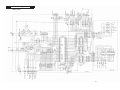
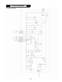
1
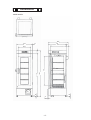
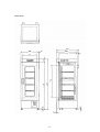
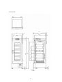
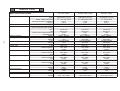
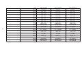
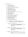
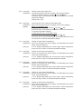
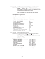
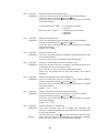
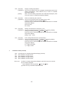
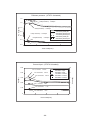
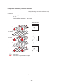
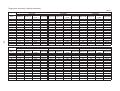
Service Manual
Blood Bank Refrigerator
MBR-305D
MBR-305DR
MBR-305GR
FILE No.
SANYO Electric Co., Ltd.
Biomedical Business Division
SM9910226
Effective models
This service manual is effective following models.
Model name
Model code
MBR-305D
MBR-305DR
MBR-305GR
823 628 62
823 628 72
823 628 51
823 628 53
823 628 54
Voltage and Frequency
220V
220V
115V
220V
220-240V
50Hz
50Hz
60Hz
60Hz
50Hz
Contents
Specifications
------------------------------------------------
1
- Structural specifications
- Control specifications
- Performance specifications
䊶Dimensions
------------------------------------------------
4
䊶Refrigeration circuit
------------------------------------------------
7
䊶Cooling unit parts
------------------------------------------------
8
䊶Specification of sensor
------------------------------------------------
9
䍃Components on PCB
------------------------------------------------
10
䊶Connection on PCB
------------------------------------------------
11
䊶Electric parts
------------------------------------------------
12
䊶Wiring diagram
------------------------------------------------
14
䊶Circuit diagram (Main PCB)
------------------------------------------------
15
------------------------------------------
16
䊶Control specifications
------------------------------------------------
17
䊶Parts layout
------------------------------------------------
32
䊶Test data
------------------------------------------------
33
䊶Circuit diagram (Control PCB)
- Pull-down speed
- Pull-up speed
- Pull-down pressure
- Pull-down current-input
- Temperature uniformity (15points measured)
- Amount of power consumption
- Maximum heat discharge
䊶Instruction manual
------------------------------------------------
38
Specifications
Structural specifications
Model
MBR-305D
MBR-305DR
MBR-305GR
External dimensions
W600 x D680 x H1835 (mm)
Internal dimensions
W520 x D490 x H1150 (mm)
Effective capacity
304 L
Exterior
Interior
Insulation
Outer door
Inner door
Outer door lock
Painted steel
Painted steel
Rigid polyurethane foamed-in place
1 door, Painted steel, provided with 2-layer glass window
2 doors, Acrylic resin
Shelf
Drawer
302 L
1
5, Hard steel wire on
polyester coating
Allowable load; 20kg/pc
㵪㵪㵪㵪㵪㵪㵪
㵪㵪㵪㵪㵪㵪㵪
5, Stainless steel
Allowable load; 20kg/pc
Caster
4 pcs (2 leveling legs on front)
Access port
1 at left side, Inner diameter; 30mm
Cooling method
Forced cool air circulation
Evaporator
Fin and tube type
Condenser
Wire and tube type
Compressor
1, Hermetic type, output: 150W
Compressor oil
㱍15HT
Refrigerant
R-134a
Illumination
1 fluorescent lamp
Weight
132 kg
147 kg
Accessories
Optional components
1 set of key
Interface board (MTR-480)
Basket (MBR-35B, MBR-55B, MBR-55BL)
-1-
Control specifications
Model
MBR-305D
Temperature controller
Temperature display
High temp.
Low temp.
Alarm
Door
MBR-305DR
MBR-305GR
Electronic control system
Sensor 䋺 Thermistor
LED digital (Unit; 0.1㷄)
When chamber temp. is higher than set temp. +6㷄 (Factory default),
ALARM lamp blinks and audible alarm sounds intermittently.
Audible alarm sounds again after 30 min. elapse if unit keeps alarming
condition.
Setting range; +5.0 ~ +9.0㷄
When chamber temp. is lower than set temp. -2 㷄 (Factory default),
ALARM lamp blinks and audible alarm sounds intermittently.
Audible alarm sounds again after 30 min. elapse if unit keeps alarming
condition.
Setting range; -1.0 ~ -4.0㷄
DOOR lamp illuminates and audible buzzer sounds intermittently after 2
min. elapses.
Power failure
ALARM lamp blinks and audible alarm sounds intermittently for 24 hours.
Remote alarm
DC30V, MAX 2A, N.O.-COM. N.C.-COM.
Remote alarm activates when unit is in alarming condition and in power
failure.
When battery accumulation time expires about 3 years (2 years and 10
months), ‘F-1’ and chamber temperature are alternately displayed.
Audible alarm and remote alarm do not activate.
When condensing fan motor accumulation time expires about 6 years (5
years and 8 months), ‘F-2’ and chamber temperature are alternately
displayed.
Audible alarm and remote alarm do not activate.
Note) Notice of fan motor life can be set alternate ON/OFF in F43.
Heater turns off and compressor turns on when temperature in mechanical
high temp. alarm thermostat is higher than +12㷄.
Compressor turns off and heater turns on when temperature in low temp.
alarm sensor is lower than +2㷄.
Cycle defrost + forced defrost
Sensor; Thermistor (Type;502AT-1)
ALARM: Alarm indicator
DOOR: Door check indicator
UPPER: Temperature display indicator
LOWER: Temperature display indicator
BUZZER: Alarm buzzer stop key
ALARM TEST: Alarm test key
UPPER/LOWER: Temperature display changeover key
CAL: Calibration key
: Scroll key
: Up arrow key
When temp. sensor or defrost sensor is failed;
Error code and chamber temperature are displayed alternately.
Remote alarm contact activates and audible alarm sounds.
Overload relay
When comp. sensor detects fan motor lock, compressor forcibly turns off
before overload activates.
Notice of battery life
Notice of fan motor life
Temperature protection
Defrosting
Control panel
Self diagnosis function
Compressor protection
-2-
Performance specifications
Model
Storage temperature
Temperature
distribution
Noise level
Maximum pressure
Rated voltage
Rated frequency
Power consumption
MBR-305D
MBR-305DR
MBR-305GR
4㷄 (AT; +35㷄)
+/- 1.5㷄
AC115V
60Hz
230W
41 dB (A scale, 50/60Hz)
1850 kPa
AC220V
AC220V
AC230V
60Hz
50Hz
50Hz
220W
205W
210W
Note) Design or specifications will be subject to change without notice.
-3-
AC240V
50Hz
220W
Dimensions
<MBR-305GR>
740
600
680
15
620
60
100
520
1835
65
65
1735
1150
490
30
-4-
<MBR-305D>
740
600
680
15
620
60
100
520
65
1835
65
1735
1150
490
10
-5-
<MBR-305DR>
740
600
680
15
620
60
210
480
65
65
210
210
1835
1735
1120
225
100
520
10
-6-
Refrigeration circuit
Condenser
Dryer
Frame pipe
-7-
Capillary tube
Evaporating pipe
Header
Evaporator
Compressor
×… Evacuation points
㩷
Cooling unit parts
㩷
㩷㩷㩷㩷㩷㩷㩷㩷㩷㩷㩷㩷㩷
Parts descriptions
Specifications
MBR-305DR
MBR-305D
MBR-305GR
Compressor
Type
Compressor code
Rated power supply
Refrigeration oil
Cooling method
Type
Compressor code
Rated power supply
Refrigeration oil
Cooling method
Type
Compressor code
Rated power supply
Refrigeration oil
Cooling method
Condenser
Type
Evaporating pipe
Frame pipe
Evaporator
Type
Capillary tube
Resistance
Length
Outer diameter
Inner diameter
Refrigerant
Type
Dryer
Type
Condensing fan motor
Type
Type
Type
For 115V, 60Hz
FL1568-PD
7FB-0-M101-010-02
Single phase, 110/115V, 60Hz
Type: 㱍15HT㩷 Charged q㵭ty: 310+/-10 ml
Forced cool air circulation
For 220/230/240V, 50Hz
FL1568-SP
7FB-0-M101-010-03
Single phase, 220-240V, 50Hz
Type: 㱍15HT 㩷 Charged q㵭ty: 310+/-10 ml
Forced cool air circulation
For 220V, 60Hz
FL1568-RB
7FB-0-M101-010-04
Single phase, 220V, 60Hz
Type: 㱍15HT 㩷 Charged q㵭ty: 310+/-10 ml
Forced cool air circulation
Wire and tube
㱢4.76 x P20 x W150 mm 11columns, Wire(P)6, 154pcs
㱢6.35 x T0.7 x W330 mm
㱢4.0 x T0.5
Fin and tube
㱢8.0 x P5 x W380 mm, 6columns x 2lines, Fin; 75pcs.
122 PSI
2000 mm
1.8 mm
0.8 mm
R-134a
4AXH-9
Charge q㵭ty: 160 g
Charge q㵭ty: 10 g
For 115V, 60Hz
FL2-D021R1MP 㱢160, 4pcs. Material: ABS Output: 2W
For 220/230/240V, 50Hz
FL2-D021R5MP 㱢160, 4pcs. Material: ABS Output: 2W
For 220V, 60Hz
FL2-D021R5MP 㱢160, 4pcs. Material: ABS Output: 2W
Cooling fan motor
Type
Type
Type
For 115V, 60Hz
FU2-C051B1MP 㱢160, 4pcs. Material: PPGF Output: 5W
For 220/230/240V, 50Hz
FU2-C051B5MP 㱢160, 4pcs. Material: PPGF Output: 5W
For 220V, 60Hz
FU2-C051B5MP 㱢160, 4pcs. Material: PPGF Output: 5W
-8-
Specifications of sensor
䂓Temperatures and references in thermistor 䋨Type: 502AT-1䋩
Temperature
(㷄)
Resistance
䋨k㱅䋩
Temperature
(㷄)
Resistance
䋨k㱅䋩
Temperature
(㷄)
Resistance
䋨k㱅䋩
-50
154.50
-7
17.92
12
8.17
-45
116.50
-6
17.16
13
7.85
-40
88.85
-5
16.43
14
7.55
-35
68.15
-4
15.74
15
7.27
-30
52.84
-3
15.08
16
6.99
-25
41.19
-2
14.45
17
6.73
-20
32.43
-1
13.86
18
6.48
-19
30.92
0
13.29
19
6.24
-18
29.50
1
12.74
20
6.01
-17
28.14
2
12.22
25
5.00
-16
26.87
3
11.72
30
4.18
-15
25.65
4
11.25
35
3.51
-14
24.51
5
10.80
40
2.96
-13
23.42
6
10.37
45
2.51
-12
22.39
7
9.96
50
2.14
-11
21.41
8
9.57
55
1.83
-10
20.48
9
9.20
60
1.57
-9
19.58
10
8.84
-8
18.73
11
8.49
䂓Temperatures and references in temp. sensor (Type:PT100 - NEW JIS)㩷
Temp.
(㷄)
Resistance
䋨 䋩
Temp.
(㷄)
Resistance
䋨 䋩
Temp.
(㷄)
Resistance
䋨 䋩
Temp.
(㷄)
Resistance
䋨 䋩
-170
31.32
-100
60.25
-30
88.22
40
115.54
-160
35.79
-90
64.30
-20
92.16
50
119.40
-150
39.82
-80
68.33
-10
96.09
60
123.24
-140
43.87
-70
72.33
0
100.00
70
127.07
-130
48.00
-60
76.33
10
103.90
80
130.89
-120
52.11
-50
80.31
20
107.80
90
134.70
-110
56.19
-40
84.27
30
116.70
100
138.50
-9-
Components on PCB
CN13
#1-#2
Comp. sensor
CN7
#7-#8 Upper sensor
#1-#2 Door Switch
#3-#4 Alarm sensor #9-#10 Lower sensor
#5-#6 Defrost sensor #11-#12 (CN73)
CN8
#1-#2
Battery, Battery SW
CN1
#1-#3
Switchig power supply
CN2
#1-#6
MTR-480
(Option)
CN4
#1-#2
Low temp. alarm relay
#3-#4 FL. relay
#5-#6 Heater relay
CN6
#1-#2
Display PCB
(CN52)
CN74
#1-#3 AT. sensor
CN5
#1-#6
Display PCB (CN51)
#7-#8 (CN73)
CN3
Remote alarm terminal
#1 COM.
#2 N.O
#3 N.C
CN73
#1-#2 (CN51)
#3-#4 Temp. sensor
#5-#6 (CN7)
- 10 -
CN72
#1-#3 Temp. control relay
Connections on PCB
䂓Connections on Main PCB
Connector
Connect to
CN1
Switching power supply
#1: +12VDC
#3: GND
CN2
MTR-480 (Option)
CN3
Remote alarm terminal
#1: COM.
#2: N.O.
#3: N.C.
Usage
To supply power to PCB
To output for remote alarm contact
CN4
#1 - #2: Low temp. alarm relay
#3 - #4: FL relay
#5 - #6: Heater relay
To operate low temp. cycle
To link between FL. Lamp and door
To supply power to main heater
CN5
#1 - #6: Display PCB (CN51)
#7 - #8: Control PCB (CN73)
To connect with each switch
CN6
#1 - #12: Display PCB (CN52)
To connect with each LED
#1 - #2
#3 - #4
: Door switch
: Alarm sensor
To detect door opening
To detect low temp in chamber
#5 - #6
: Defrost sensor
To detect frosting in chamber
#7 - #8
#9 - #10
: Upper sensor
: Lower sensor
To detect upper bottle temperature
To detect lower bottle temperature
#11 - #12
: Control PCB (CN73)
CN7
CN8
#1 - #2: Battery, Battery switch
To control battery ON/OFF
CN13
#1 - #2: Comp. sensor
To detect fan motor lock
䂓Connections on Control PCB
Connector
Connect to
Usage
CN71
#1 - #2: Switching power supply
To supply power to PCB
CN72
#1 - #3: Temp. control relay
To control chamber temperature
CN73
#1 - #2: Display PCB (CN51)
#3 - #4: Temp. sensor
#5 - #6: Main PCB (CN7)
To detect chamber temperature
CN74
#1 - #3: AT sensor
To detect ambient temperature
- 11 -
Electric Parts
MBR-305D/305DR/305GR
Compressor
PTC
Overload relay
Starting capacitor
Cooling fan motor
- 12 -
Condensing fan motor
Main heater
Heater relay
Temp. control relay
Low temp. alarm relay
FL relay
High temp.thermo
Fluorescent lamp
Glow starter
Ballast
Type
Code
Rated voltage (50/60Hz)
Winding resistance C-R(Main)
C-S(Aux)
Type
Type
Action to the temp. (No current)
OFF
ON
Action to the current (AT25͠)
Operation time
Rating
Type
Rating
Type
Rating
Rating
Type
Contact capacity
Coil
Type
Contact capacity
Coil
Type
Contact capacity
Coil
Type
Contact capacity
Coil
Type
Rating
Type
Rating
Type
Type
Rating
AC115V, 60Hz
AC220~240V, 50Hz
AC220V, 60Hz
FL1568-PD
7FB-0-M101-010-02
㱢1, 110/115V, 60Hz
2.16㱅
4.56㱅
P5R0SAT
4.0C36C1
FL1568-SP
7FB-0-M101-010-03
㱢1, 220-240V, 50Hz
11.4㱅
19.5㱅
PGR0SAT
2.0C36C3
FL1568-RB
7FB-0-M101-010-04
㱢1, 220V, 60Hz
8.64㱅
9.23㱅
PER0SAT
2.0C36C3
130+8/-9㷄
60+7/-5㷄
12.2A
10 sec
120μF 160VAC
FU2-C051B1MP
115V
FL2-D021R1MP
110V
50W
G2R-1A-T
10A, 250V
12VDC
G4F-1123T
20A, 250V
12VDC
G4F-1123T
20A, 250V
12VDC
G2R-1A-T
10A, 250V
12VDC
WP9K-114-011
250V
FL15SD
15W
FG-1P
FCB-1587115A
15W, 115V, 60Hz
130+8/-9㷄
60+7/-5㷄
7.6A
10 sec.
60μF 300VAC
FU2-C051B5MP
220-240V
FL2-D021R5MP
220-240V
50W
G2R-1A-T
10A, 250V
12VDC
G4F-1123T
20A, 250V
12VDC
G4F-1123T
20A, 250V
12VDC
G2R-1A-T
10A, 250V
12VDC
WP9K-114-011
250V
FL15SD
15W
FG-1P
FCB-152022/2
15W, 220V, 60Hz
130+8/-9㷄
60+7/-5㷄
7.6A
10 sec.
60μF 300VAC
FU2-C051B5MP
220-240V
FL2-D021R5MP
220-240V
50W
G2R-1A-T
10A, 250V
12VDC
G4F-1123T
20A, 250V
12VDC
G4F-1123T
20A, 250V
12VDC
G2R-1A-T
10A, 250V
12VDC
WP9K-114-011
250V
FL15SD
15W
FG-1P
FCB-152022/2
15W, 220V, 60Hz
Temp. sensor
AT sensor
Comp. sensor
Lower sensor
Upper sensor
Defrost sensor
Alarm sensor
Switching power supply
Battery switch
- 13 -
Battery
Breaker switch
Door switch
FL lamp switch
Test switch
Noise filter
Type
Rating
Type
Rating
Type
Rating
Type
Rating
Type
Rating
Type
Rating
Type
Rating
Type
Rating
Type
Rating
Type
Rating
Type
Rating
Type
Rating
Type
Rating
Type
Rating
Type
Rating
TRP-2-SP-REG
PT100㱅
502AT
5K 25㷄
502AT
5K 25㷄
502AT
5K 25㷄
502AT
5K 25㷄
502AT
5K 25㷄
502AT
5K 25㷄
ZWS10-12/J
DC12V, 0.85A
SLE6A2-5
4A, 250VAC
5HR-AAC
6V, 1100MAH
BAM210131
250V, 10A
SDKNA20700
5V, 5MA
MS152W1-A01
DC8V, 1A
SLE6D2-5
4A, 250VAC
ZHG2210-11S
10A, 250VAC
TRP-2-SP-REG
PT100㱅
502AT
5K 25㷄
502AT
5K 25㷄
502AT
5K 25㷄
502AT
5K 25㷄
502AT
5K 25㷄
502AT
5K 25㷄
ZWS10-12/J
DC12V, 0.85A
SLE6A2-5
4A, 250VAC
5HR-AAC
6V, 1100MAH
BAM210131
250V, 10A
SDKNA20700
5V, 5MA
MS152W1-A01
DC8V, 1A
SLE6D2-5
4A, 250VAC
ZHG2210-11S
10A, 250VAC
TRP-2-SP-REG
PT100㱅
502AT
5K 25㷄
502AT
5K 25㷄
502AT
5K 25㷄
502AT
5K 25㷄
502AT
5K 25㷄
502AT
5K 25㷄
ZWS10-12/J
DC12V, 0.85A
SLE6A2-5
4A, 250VAC
5HR-AAC
6V, 1100MAH
BAM210131
250V, 10A
SDKNA20700
5V, 5MA
MS152W1-A01
DC8V, 1A
SLE6D2-5
4A, 250VAC
ZHG2210-11S
10A, 250VAC
Wiring diagram
- 14 -
Circuit diagram
< Main
PCB >
<Main
PCB>
- 15 -
Circuit Diagram
<Control PCB>
- 16 -
Control specifications
1.
Keys on control panel
BUZZER
: When a unit is in alarming condition, press this key to stop audible
alarm sounding and to turn remote alarm off.
Alarm message remains to display.
This key is inoperative during an alarm test performs.
UPPER/LOWER
Display temperature is changed to the following order every time
pressing this key.
Mean temp. (Factory default) => Upper bottle temp. => Lower bottle
temp. => Mean temp. ...
ALARM TEST
:
Press this key to perform an alarm test.
ALARM lamp blinks, audible alarm sounds and remote alarm contact
turns on.
If there are no key operations for 90 seconds, a unit has alarm test
come to the end.
If this key is pressed during alarm test performs, a unit has alarm test
come to the end.
This key is inoperative when a unit is actually in alarming condition.
CAL
:
Press this key for 5 seconds to step to calibration mode (C-mode).
This key acts as ‘Enter key’ during a unit is in C-mode or function
mode (F-mode).
:
This key is used in C-mode and F-mode. Press this key to shift digit to
be changed.
(Up arrow key):
This key is used in C-mode and F-mode. Press this key to change
numerical value.
(Scroll key)
2.
:
Temperature setting and function
(1) Temperature setting
Setting range: +2.0 ~ +9.0͠ (Turn a volume on control panel)
How to set: Step to F-mode, ‘F38’ to display setting temperature in control PCB.
Turn a volume, ‘VR1’ to set temperature.
Press CAL key to return to chamber temperature display.
Ex.) If a measured temperature will be set to 4.0͠ when it is actually
3.6͠ while a display temperature in F38 is ‘4.0’, turn ‘VR1’ until
the display temperature will be ‘4.4’.
Note) If you turn VR1 without displaying control PCB temperature, it
may be caused to change temperature setting.
- 17 -
(2) Function mode (F-mode)
Setting range: 0 ~ 45
Display range: 0 ~ 49
(05, 07, 08, 10, 18~20, 23, 24, 26~29, 31, 39~42, 46~49 are unused.)
How to set: In chamber temperature display, press key for 5 seconds to step to
function mode and ‘F00’ is displayed with 1st digit blinks.
Change a value by pressing
key and
key.
Press CAL key to activate function mode.
Unacceptable setting If a value which is out of setting range is input and CAL key is pressed,
range: error tone emits and setting will not be changed.
(3) Calibration mode (C-mode)
Setting range: 0 ~ 4
Display range: 0 ~ 4
How to set: In chamber temperature display, press
key for 5 seconds to step
to calibration mode and ‘C00’ is displayed with 1st digit blinks.
Change a value by pressing
key and
key.
Press CAL key to activate calibration mode.
Unacceptable setting If a value which is out of setting range is input and CAL key is pressed,
range: error tone emits and setting will not be changed.
3.
Error codes and Notice
E03:
E04:
E05:
E06:
E10:
E13:
E14:
E15:
E16:
E17:
E18:
E2P:
F-1:
F-2:
Defrost sensor is open circuited
Defrost sensor is short circuited
Comp. sensor is open circuited
Comp. sensor is short circuited
Compressor temperature is abnormal
Alarm sensor is open circuited
Alarm sensor is short circuited
Upper sensor is open circuited
Upper sensor is short circuited
Lower sensor is open circuited
Lower sensor is short circuited
Unit fails to write data in non-volatile memory
Notice of battery life
Notice of condensing fan motor life
Following shows the descriptions of error codes and notices.
E03:
When a temperature in defrost sensor is lower than -60͠, a unit diagnoses that
the sensor is open circuited and ‘E03’ and chamber temperature are displayed
alternately. Audible alarm sounds and remote alarm activates.
At the time the unit does not perform defrosting.
By pressing BUZZER key to cancel operations for audible alarm and remote
alarm when E03 emits.
- 18 -
E04:
When a temperature in defrost sensor is higher than +60͠, a unit diagnoses that
the sensor is short circuited and ‘E04’ and chamber temperature are displayed
alternately. Audible alarm sounds and remote alarm activates.
At the time the unit does not perform defrosting.
By pressing BUZZER key to cancel operations for audible alarm and remote
alarm when E04 emits.
E05:
When a temperature in comp. sensor is lower than -60͠, a unit diagnoses that
the sensor is open circuited and ‘E05’ and chamber temperature are displayed
alternately. Audible alarm sounds and remote alarm activates.
By pressing BUZZER key to cancel operations for audible alarm and remote
alarm when E05 emits.
E06:
When a temperature in comp. sensor is higher than +60͠, a unit diagnoses that
the sensor is short circuited and ‘E06’ and chamber temperature are displayed
alternately. Audible alarm sounds and remote alarm activates.
By pressing BUZZER key to cancel operations for audible alarm and remote
alarm when E06 emits.
E10:
When a temperature in comp. sensor is higher than +57͠, a unit diagnoses that
fan motor is locked.
E10’ and chamber temperature are displayed alternately, and both compressor
and heater are turned off.
At the time audible alarm and remote alarm do not activate.
Compressor and heater turn on as soon as a temperature in comp. sensor will be
lower than 45͠.
E13:
When a temperature in alarm sensor is lower than -60͠, a unit diagnoses that
the sensor is open circuited, and ‘E13’ and chamber temperature are displayed
alternately. Audible alarm sounds and remote alarm activates.
Temperature alarm is controlled by chamber temperature (temperature in
upper/lower sensor).
By pressing BUZZER key to cancel operations for audible alarm and remote
alarm when E13 emits.
E14:
When a temperature in alarm sensor is higher than +60͠, a unit diagnoses that
the sensor is short circuited, and ‘E14’ and chamber temperature are displayed
alternately. Audible alarm sounds and remote alarm activates.
Temperature alarm is controlled by chamber temperature (temperature in
upper/lower sensor).
By pressing BUZZER key to cancel operations for audible alarm and remote
alarm when E14 emits.
E15:
When a temperature in upper sensor is lower than -60͠, a unit diagnoses that
the sensor is open circuited, and ‘E15’ and chamber temperature are displayed
alternately. Audible alarm sounds and remote alarm activates.
At the time a unit cannot detect high and low temperature alarm.
By pressing BUZZER key to cancel operations for audible alarm and remote
alarm when E15 emits.
- 19 -
E16:
When a temperature in upper sensor is higher than +60͠, a unit diagnoses that
the sensor is short circuited, and ‘E16’ and chamber temperature are displayed
alternately. Audible alarm sounds and remote alarm activates.
At the time a unit cannot detect high and low temperature alarm.
By pressing BUZZER key to cancel operations for audible alarm and remote
alarm when E16 emits.
E17:
When a temperature in lower sensor is lower than -60͠, a unit diagnoses that the
sensor is open circuited, and ‘E17’ and chamber temperature are displayed
alternately. Audible alarm sounds and remote alarm activates.
At the time a unit cannot detect high and low temperature alarm.
By pressing BUZZER key to cancel operations for audible alarm and remote
alarm when E17 emits.
E18:
When a temperature in lower sensor is higher than +60͠, a unit diagnoses that
the sensor is short circuited, and ‘E18’ and chamber temperature are displayed
alternately. Audible alarm sounds and remote alarm activates.
At the time a unit cannot detect high and low temperature alarm.
By pressing BUZZER key to cancel operations for audible alarm and remote
alarm when E18 emits.
E2P:
When a unit fails to write data in non-volatile memory, ‘E2P’ and chamber
temperature are displayed alternately.
Audible alarm and remote alarm do not activate.
F-1:
When battery accumulation time expires about 3 years (1022days), ‘F-1’ and
chamber temperature are alternately displayed.
Unit starts counting accumulation time every 24 hours elapse since a power is
supplied.
Audible alarm and remote alarm do not activate.
Input ‘409’ in F06 and press CAL key to reset accumulation time to ‘0’.
If a unit forcibly turns off before 24 hours elapse since the power supplied, it is
ineffective for counting accumulation time until 24 hours elapse.
F-2:
When condensing fan motor accumulation time expires about 6 years
(2044days), ‘F-2’ and chamber temperature are alternately displayed.
Unit starts counting accumulation time every 24 hours elapse since a power is
supplied.
Audible alarm and remote alarm do not activate.
Input ‘410’ in F06 and press CAL key to reset accumulation time to ‘0’.
If a unit forcibly turns off before 24 hours elapse since the power supplied, it is
ineffective for counting accumulation time until 24 hours elapse.
Note) If notice of fan motor life is set to ‘0’ (Not notify) in F43, ‘F-2’ will not emit.
- 20 -
Error code priority:
E03/E04 (Open/short circuit in defrost sensor)
High
E05/E06 (Open/short circuit in comp. sensor)
E10 (Compressor temperature is abnormal)
E13/E14 (Open/short circuit in alarm sensor)
E15/E16 (Disable to detect high/low temp. alarm)
E17/E18 (Disable to detect high/low temp. alarm)
E2P (Disable to memorize setting value)
F-1 (Notice of battery life)
F-2 (Notice of condensing fan motor life)
Low
4.
Alarms
High temp. alarm:
When one of bottle temperature which is higher than the other between
upper and lower bottle is equal or higher than SVH (high temp. alarm
set temperature) + 0.09, ALARM lamp and LED digits blink, audible
alarm sounds intermittently, remote alarm turns on.
When one of bottle temperature which is higher than the other between
upper and lower bottle is equal or lower than SVH, ALARM lamp goes
off, LED digits stops blinking, audible alarm silences, remote alarm
turns off.
Press BUZZER key to cancel operations for audible alarm and remote
alarm during unit is in alarming condition.
High temp. alarm setting temperature is changeable in F01.
(Factory default: 6͠)
Low temp. alarm:
When one of bottle temperature which is lower than the other between
upper and lower bottle is lower than SVL (low temp. alarm set
temperature) -0.09, ALARM lamp and LED digits blink, audible alarm
sounds intermittently, remote alarm turns on.
When one of bottle temperature which is lower than the other between
upper and lower bottle is equal or higher than SVL, ALARM lamp goes
off, LED digits stops blinking, audible alarm silences, remote alarm
turns off.
Press BUZZER key to cancel operations for audible alarm and remote
alarm during unit is in alarming condition.
Low temp. alarm setting temperature is changeable in F02.
(Factory default: 2͠)
Door alarm:
When a door leaves open, DOOR lamp illuminates and audible alarm
sounds intermittently after delay time elapses. Audible alarm does not
link with remote alarm. Press BUZZER key to cancel an operation for
audible alarm. (Ring Back does not activate).
Power failure alarm:
When a power switch is in off position or a power is interrupted,
ALARM lamp blinks, LED digits go off, audible alarm sounds
intermittently, remote alarm turns on.
Operations for audible alarm and remote alarm are not cancelled by
pressing BUZZER key.
Unit will start an operation with initial setting after it returns from a
power failure. Remote alarm will not turn on.
- 21 -
5.
Representative functions
Auto Return:
If there are no key operations for 90 seconds during calibration mode
and function mode, unit will automatically return to chamber
temperature display.
Ring Back:
Audible alarm will sound again after predetermined setting time
elapses if BUZZER key is pressed to cancel operation for audible
alarm.
Ring Back time is changeable in F25. (Factory default: 30 minutes)
Example display of
sensor temperature:
When upper sensor temp. is +5.4͠ => Display indicates as ‘5.4’
When lower sensor temp. is -5.4͠ => Display indicates as ‘-5.4’
When lower sensor temp. is -20.3͠ => Display indicates as ’20.3’
When defrost sensor temp. is -5.4͠ => Display indicates as ‘-5.4’
When defrost sensor temp. is -20.3͠ => Display indicates as ’20.3’
When comp. sensor temp. is +36.2͠ => Display indicates as ’36.2’
When alarm sensor temp. is +5.4͠ => Display indicates as ’05.4’
Note) When comp. sensor temp. is higher than 99.9͠, display will
indicate as ’99.9’.
Battery
accumulation time:
Battery accumulation time is displayed in F03.
When battery accumulation time expires 2.5 years, display indicates
as ’02.5’
When battery accumulation time expires about 3 years, ‘F-1’ is
displayed.
Input ‘409’ and press CAL key to reset non-volatile memory to ’00.0’.
Condensing fan
motor accumulation
time:
Condensing fan motor accumulation time is displayed in F32.
When condensing fan motor accumulation time expires 5.3 years,
display indicates as ’05.3’.
When notice of fan motor life is selected to ‘001’ (notify) in F43 and
accumulation time expires about 6 years, ‘F-2’ is displayed.
Input ‘410’ and press CAL key to reset non-volatile memory to ’00.0’.
Display of ROM
version:
Installed ROM version can be checked in F30.
When a ROM version is 1.00, display indicates as ‘1.00’.
- 22 -
6.
Function mode (F-mode)
F01:
F02:
F03:
F04:
F06:
F09:
F11:
F12:
F13:
F14:
F15:
F16:
F17:
F21:
F22:
F25:
F30:
F32:
F33:
F34:
F35:
F36:
F37:
F38:
F43:
F44:
F45:
Setting of high temp. alarm
Setting of low temp. alarm
Display of battery accumulation time
Setting of door alarm delay time
Input of service code and reset of accumulation time
Compressor continuous running mode (Unused)
PCB test mode (Unused)
Display of upper sensor temperature
Display of lower sensor temperature
Display of defrost sensor temperature
Display of comp. sensor temperature
Display of alarm sensor temperature
Setting of model code and data initialization in non-volatile memory
Setting of communication ID
Setting of communication mode
Setting of Ring Back time
Display of ROM version
Display of condensing fan motor accumulation time
Setting of temperature to start defrosting
Setting of temperature to terminate defrosting
Defrost operation check mode (Unused)
Display of frequency of defrosting
High temp. alarm operation check (Unused)
Display of setting temperature
Notice of condensing fan motor life
Setting of temperature for low temp. cycle
Action linkage between door and illumination
How to set:
(1) Press key for 5 seconds in chamber temperature is displayed.
(2) ‘F00’ is displayed. Input function code by pressing key and
key.
(3) Press CAL key to step to required function mode.
F01:
[Purpose]
[Operation]
Setting of high temp. alarm
Input ‘F01’ and press CAL key to display ’06.0’ (Factory default).
Input required value by pressing key and
key.
Press CAL key to memorize the value and unit will return to chamber
temperature display.
(Range: 05.0 ~ 09.9)
F02:
[Purpose]
[Operation]
Setting of low temp. alarm
Input ‘F02’ and press CAL key to display ’02.0’ (Factory default).
Input required value by pressing key and
key.
Press CAL key to memorize the value and unit will return to chamber
temperature display.
(Range: 01.0 ~ 04.0)
F03:
[Purpose]
[Operation]
Display of battery accumulation time
Input ‘F03’ and press CAL key to display alternately F03 with battery
accmulation time. Press CAL key to return to chamber temperature
display.
Note) If accmulation time is less than 36days, ’00.0’ will be displayed.
- 23 -
F04:
[Purpose]
[Operation]
Setting of door alarm delay time
Input F04 and press CAL key to display ‘002’ (Factory default).
Change to requried value by pressing key and
key.
Press CAL key to memorize the value and unit will return to chamber
temperature display.
(Range: 000~ 012)
F06:
[Purpose]
[Operation]
[Reset]
Input of service code, reset of accumulation time
Input ‘F06’ and press CAL key to display ‘000’ (Factory default).
Battery accumulation time:
Change a value to ‘409’ by pressing key and
key.
Press CAL key to reset battery accumulation time and unit will return
to chamber temperature display.
Condensing fan motor accumulation time:
Change a value to ‘410’ by pressing key and
key.
Press CAL key to reset condensing fan motor accumulation time and
unit will return to chamber temperature display.
F12:
[Purpose]
[Operation]
Display of upper sensor temperature
Input ‘F12’ and press CAL key to display ‘F12’ alternately with current
upper sensor temperature.
In ‘F12’ displays alternately with current upper sensor temperature,
press CAL key to return to chamber temperature display.
[Cancel]
F13:
[Purpose]
[Operation]
[Cancel]
F14:
[Purpose]
[Operation]
[Cancel]
F15:
[Purpose]
[Operation]
[Cancel]
F16:
[Purpose]
[Operation]
[Cancel]
Display of lower sensor temperature
Input ‘F13’ and press CAL key to display ‘F13’ alternately with current
lower sensor temperature.
In ‘F13’ displays alternately with current lower sensor temperature,
press CAL key to return to chamber temperature display.
Display of defrost sensor temperature
Input ‘F14’ and press CAL key to display ‘F14’ alternately with current
defrost sensor temperature.
In ‘F14’ displays alternately with current defrost sensor temperature,
press CAL key to return to chamber temperature display.
Display of comp. sensor temperature
Input ‘F15’ and press CAL key to display ‘F15’ alternately with current
comp. sensor temperature.
In ‘F15’ displays alternately with current comp. sensor temperature,
press CAL key to return to chamber temperature display.
Display of alarm sensor temperature
Input ‘F16’ and press CAL key to display ‘F16’ alternately with current
alarm sensor temperature.
In ‘F16’ displays alternately with current alarm sensor temperature,
press CAL key to return to chamber temperature display.
- 24 -
F17:
[Purpose]
[Operation]
Setting of model code, data initialization in non-volatile memory
Input ‘F17’ and press CAL key to display current model code.
Change to ‘001’ (Model code for MBR-305GR/305D/305DR) by
pressing
key and
key.
Press CAL key to memorize the value in non-volatile memory and
unit will return to chamber temperature display.
Note) It is necessary to set model code when PCB is replaced.
[Initial values in non-volatile memory]
Zero adjustment for upper sensor
Zero adjustment for lower sensor
Temperature to start defrosting
Temperature to terminate defrosting
Temperature for low temp cycle
Action linkage between door and illumination
High temp. alarm temperature
Low temp. alarm temperature
Door alarm delay time
Span adjustment for upper sensor
Span adjustment for lower sensor
Ring Back time
Communication ID
Communication mode
Non-volatile memory check data
Battery accumulation time
Condensing fan motor accumulation time
Notice of condensing fan motor life
F21:
[Purpose]
[Operation]
: 000
: 000
: -15͠
: 5͠
: 2͠
: 0 (Not linked)
: 6͠
: 2͠
: 2 minutes
: 100
: 100
: 30 minutes
: 000
: 000
:
:0
:0
: OFF
Setting of serial communication ID
Input ‘F21’ and press CAL key to display ‘000’ (Factory default).
Change a value by pressing
key and
key.
Press CAL key to memorize the value and unit will return to chamber
temperature display.
(Range: ‘001’ ~ ‘255’)
[Serial communication data]
Mean between upper and lower sensor temp. : -60.0 ~ +60.0 (͠)
Upper sensor temperature
: -60.0 ~ +60.0 (͠)
Lower sensor temperature
: -60.0 ~ +60.0 (͠)
Defrost sensor temperature
: -60.0 ~ +60.0 (͠)
Power failure
: 0/100 (Yes/No)
Comp. sensor temperature
: -60.0 ~ +60.0 (͠)
Door status
: 0/100 (Open/Close)
Set temp. for temp. control PCB
: -60.0 ~ +60.0 (͠)
Alarm sensor temperature
: -60.0 ~ +60.0 (͠)
High temp. alarm set temperature
: 5.0 ~ 9.9 (͠)
Low temp. alarm set temperature
: 1.0 ~ 4.0 (͠)
- 25 -
F22:
[Purpose]
[Operation]
Setting of serial communication mode
Input ‘F22’ and press CAL key to display ‘000’ (Factory default).
Change a value by pressing
key and
key.
Press CAL key to memorize the value and unit will return to chamber
temperature display.
Control mode (The 3rd digit)
Baud rate (The 2nd digit)
0: Local (Factory default)
1: Remote
0: 2400 bps (Factory default)
1: 4800 bps
2: 9600 bps
F25:
[Purpose]
[Operation]
Setting of Ring Back time
Input ‘F25’ and press CAL key to display ‘030’ (Factory default).
Change a value by pressing
key and
key.
Press CAL key to memorize the value and unit will return to chamber
temperature display.
(Range: ‘010’ ~ ‘099’)
F30:
[Purpose]
[Operation]
Display of ROM version
Input ‘F30’ and press CAL key to display F30 alternately with ‘X.XX’
(current ROM version).
Press CAL key to return to chamber temperature display.
F32:
[Purpose]
[Operation]
Display of condensing fan motor accumulation time
Input ‘F32’ and press CAL key to display F32 alternately with ‘XX.X’
(condensing fan motor accumulation time).
Press CAL key to return to chamber temperature display.
Note) If an accumulation time is less than 36days, ’00.0’ will be
displayed.
F33:
[Purpose]
[Operation]
Setting of temperature which starts defrosting
Input ‘F33’ and press CAL key to display ‘-12.0’ (Factory default).
Change a value by pressing
key and
key.
Press CAL key to memorize the value and unit will return to chamber
temperature display.
(Range: ‘-10.0’ ~ ‘-19.9’)
F34:
[Purpose]
[Operation]
Setting of temperature which terminates defrosting
Input ‘F34’ and press CAL key to display ’05.0’ (Factory default).
Change a value by pressing
key and
key.
Press CAL key to memorize the value and unit will return to chamber
temperature display.
(Range: ‘0.0’ ~ ‘9.9’)
F36:
[Purpose]
[Operation]
Display of frequency of defrosting
Input ‘F36’ and press CAL key to display F36 alternately with
frequency of defrosting (Maximum: 999) that has been counted since
a power was supplied.
Turn the power off or press
key over 5 seconds to reset counting.
When F36 and frequency of defrosting are alternately displayed,
press CAL key to return to chamber temperature display.
[Reset]
- 26 -
F38:
[Purpose]
[Operation]
[Reset]
7.
Display of setting temperature
Input ‘F38’ and press CAL key to display F38 alternately with ‘XX.X’
(setting temperature). Press SET/CAL key to return to chamber
temperature display.
When F38 and setting temperature are alternately displayed, press
CAL key to return to chamber temperature display.
F43:
[Purpose]
[Operation]
Notice of condensing fan motor life
Input ‘F43’ and press CAL key to display ‘000’ or ‘001’.
Change to alternate value by pressing
key.
Press CAL key to memorize the value and unit will return to chamber
temperature display.
000: Not notify
001: Notify
F44:
[Purpose]
[Operation]
Setting of temperature for low temp. cycle
Input ‘F44’ and press CAL key to display ’02.0’ (Factory default).
Change a value by pressing
key and
key.
Press CAL key to memorize the value and unit will return to chamber
temperature display.
(Range: ‘000’ ~ ‘030’)
F45:
[Purpose]
[Operation]
Action linkage between door and illumination
Input ‘F45’ and press CAL key to display ‘000’ (Factory default).
Change a value by pressing
key and
key.
Press CAL key to memorize the value and unit will return to chamber
temperature display.
0 (1st digit): Not linked
1 (1st digit): Linked
Calibration mode (C-mode)
C00:
C01:
C02:
C03:
C04:
Unit will return to chamber temperature display (Unused)
Zero calibration of upper sensor
Zero calibration of lower sensor
Span calibration of upper sensor
Span calibration of lower sensor
How to set:
(1) When a chamber temperature displays, press CAL key for 5 seconds
(2) ‘C00’ will be displayed.
Input calibration code by pressing
key and
key.
(3) Press CAL key to activate calibration mode.
- 27 -
C01:
[Purpose]
[Operation]
Zero calibration of upper sensor
Press UPPER/LOWER key to display upper sensor temperature
(Range: -1.5~+1.5͠). If upper sensor temperature is out of range,
unit will not commance calibration and buzzer tone will emit.
Put upper sensor into fully stirred ice water and leave it until
temperature display stabilizes.
Press CAL key for 5 seconds to display ‘C00’.
Change to ‘C01’ by pressing
key.
Press CAL key to terminate calibration and to return to chamber
temperature display.
Note) Ensure to repeat the procedure until a displayed temperature
should be almost 0͠.
C02:
[Purpose]
[Operation]
Zero calibration of lower sensor
Press UPPER/LOWER key to display lower sensor temperature
(Range: -1.5~+1.5͠). If lower sensor temperature is out of range,
unit will not commance calibration and buzzer tone (1 second) will
emit.
Put upper sensor into fully stirred ice water and leave it until
temperature display stabilizes.
Press CAL key for 5 seconds to display ‘C00’.
Change to ‘C02’ by pressing
key.
Press CAL key to terminate calibration and to return to chamber
temperature display.
Note) Ensure to repeat the procedure until a displayed temperature
should be almost 0͠.
C03:
[Purpose]
[Operation]
Span calibration of upper sensor
Press CAL key for 5 seconds to display ‘C00’.
Change to ‘C03’ by pressing key.
Press CAL key to display lower sensor temperature.
Change to a correct value by pressing
key and
key.
(Range: +3.0 ~ +5.9͠)
If a value deviates from the range, unit will not commance calibration
and buzzer tone (1 second) will emit.
Press CAL key to terminate calibration and to return to chamber
temperature display.
C04:
[Purpose]
[Operation]
Span calibration of lower sensor
Press CAL key for 5 seconds to display ‘C00’.
Change to ‘C03’ by pressing key.
Press CAL key to display lower sensor temperature.
Change to a correct value by pressing
key and
key.
(Range: +3.0 ~ +5.9͠)
If a value deviates from the range, unit will not commance calibration
and buzzer tone (1 second) will emit.
Press CAL key to terminate calibration and to return to chamber
temperature display.
- 28 -
8.
Temperature control
(1)
Low temperature cycle
When alarm sensor temperature is lower than +2͠, alarm relay turns on.
(Compressor turns off and heater is energized)
When alarm sensor temperature is higher than +2͠, alarm relay turns off.
(Compressor and heater are controlled by temperature control PCB)
Setting temperature for low temp. cycle is changeable in F44.
There is 3 minutes to restart compressor after it stopped once, even if it meets condition
that compressor would start soon.
9.
(2)
When alarm sensor fails during low temperature cycle
Upper/lower sensor will be used instead of alarm sensor.
When low temp. alarm emits, alarm relay turns on.
(Compressor turns off and heater is energized)
When low temp. alarm is cancelled, alarm relay turns off.
(Compressor and heater are controlled by temperature control PCB)
(3)
Compressor protection
When condensing fan motor is locked, compressor will turn off to prevent discharge
pressure in compressor from being increased.
When comp. sensor temperature is higher than +57͠, compressor will turn off.
When comp. sensor temperature is lower than +45͠, compressor will turn on.
Defrosting
By detecting a defrost sensor temperature in evaporating pipe and controlling compressor
and heater, unit will perform defrosting around evaporator.
During defrosting, a unit will display chamber temperature and ‘dF’ alternately.
(1)
Forcible defrosting
When a defrost sensor temperature is lower than -12͠ (Factory default), a unit will
forcibly commance defrosting.
When a defrost sensor temperature is higher than +5 ͠ (Factory default) during
defrosting, a unit will terminate defrosting.
A temperature that commances defrosting is changeable in F33.
A temperature that terminates defrosting is changeable in F34.
(2)
Count of frequency of defrosting
Count will be checked in F36.
- 29 -
10.
11.
Delay time
(1)
Compressor delay time (3 minutes, fixed)
When a unit cycle runs, it takes 3 minutes to turn on compressor after it was turned off.
There are no delay time after a unit was energized (reset).
(2)
Door alarm delay time (2 minutes, factory default)
There is delay time to emit audible alarm when a door leaves open.
Delay time is changeable in F04.
Remote alarm contact
Normal
In alarm
12.
CN3
Between #1 and #2 (N.O.)
Between #1 and #3 (N.C.)
Open
Close
Close
Open
Settings after a power is supplied (Power on reset)
Alarms
Compressor
Defrosting
Compressor protection
Remote alarm
Ring Back
Door alarm delay time
Timer
Setting data
13.
: Ineffective
: Turns off
: Ineffective
: Ineffective
: Turns off
: Ineffective
: 2 minutes
: Reset
: Read by non-volatile memory
Lamp operation
(1)
Display PCB
DP51:
DP52:
DP54:
DP55:
(ALARM) Red lamp blinks when a unit is in alarming condition.
(DOOR) Red lamp illuminates when a door leaves open.
(Upper limit temp.) Green lamp illuminates when upper sensor
temperature is displayed.
(Lower limit temp.) Green lamp illuminates when lower sensor
temperature is displayed.
- 30 -
(2)
Main PCB
DP1:
DP2:
DP3:
DP4:
14.
Examples of LED display
Chamber temp.㩷
Temp. to start defrosting㩷 㩷 -12.0
㩷 㩷 㩷 㪋㪅㪇㷄㩷
Function mode㩷 㩷
F03
Forcible defrosting㩷 㩷 㩷 㩷
Calibration mode㩷
C01
Error code
㩷 㩷 㩷 㩷 E01
㩷 㩷 㩷 409
Battery life
㩷㩷㩷
Service code
Setting value㩷 㩷 㩷
15.
(Alarming operation)
Orange lamp illuminates when a unit is not in alarming condition.
Orange lamp goes off when high/low temp. alarm emit or sensor is failed.
(Temperature control)
Green lamp illuminates when a compressor turns off.
Green lamp goes off when a temp. control PCB activates.
(Illumination)
Red lamp illuminates when fluorescent lamp illuminates.
Red lamp goes off when fluorescent lamp goes off.
(Heater operation)
Yellow lamp illuminates when defrost heater turns on.
Yellow lamp goes off when defrost heater turns off.
004
Buzzer tone
Alarms
Key operation
Set value memorization
Out of setting range
Power failure
: Intermittent tone
: Short tone
: Short tone
: 1 second alarming tone
: intermittent tone
- 31 -
dF
F-1
Parts layout
Light switch
Electric components (Top)
Volume for temperature control
(Cover is removed)
Control panel
Fluorescent lamp
Glow starter
Right side
Power switch
Battery
Swiching power supply
Cover is removed
AT sensor
Door alarm swtich
Battery switch
Test switch
Latch
Monitor bottle, upper
Main PCB
Control PCB
Power source for recorder
Temperature recorder
Upper sensor
Monitor bottle, lower
Air exhaust vent
Lower sensor
- 32 -
Test data
Note) Following data are the reference only.
Pulldown speed䇭(AT35㷄 Unloaded)
40
115V,60Hz (drawer)
230V,50Hz (shelf)
220V,60Hz (drawer)
Chamber temperature(㷄)
35
30
25
20
15
10
5
0
-5
-10
-15
-20
0
2
4
6
8
10
Time scale(hour)
Pullup speed䇭(AT35㷄 Unloaded)
40
35
Chamber temperatur(㷄)
30
25
20
15
10
5
0
Shelf
Drawer
-5
-10
-15
-20
0
1
2
3
4
5
6
Time scale(hour)
- 33 -
7
8
9
10
Pulldown pressure䇭(AT35㷄 Unloaded)
1.8
Peak(115V60Hz)䇭1.743Mpa
Peak(220V60Hz) 䇭1.690Mpa
Pd , Ps(MPa)
1.5
1.2
Peak(230V50Hz) 䇭1.527Mpa
0.9
Peak(115V60Hz)
0.227Mpa
0.6
Peak(220V60Hz)
0.234Mpa
115V60Hz (Drawer) Pd
230V50Hz (Shelf) Pd
220V60Hz (Drawer) Pd
115V60Hz (Drawer) Ps
230V50Hz (Shelf) Ps
220V60Hz (Drawer) Ps
0.3
Peak(230V50Hz)
0.163Mpa
0.0
0
2
4
6
8
Time scale(hour)
Current-Input䇭(AT35㷄 Unloaded)
㪧㪼㪸㫂㩷㩿㪈㪈㪌㪭㪍㪇㪟㫑㪀㩷㩷㩷㩷㪉㪏㪊㪅㪊㪮
㪧㪼㪸㫂㩷㩿㪉㪉㪇㪭㪍㪇㪟㫑㪀㩷㩷㩷㪉㪋㪐㪅㪎㪮
400
Input(W)
㪧㪼㪸㫂㩷㩿㪉㪊㪇㪭㪌㪇㪟㫑㪀㩷㩷㩷㪉㪋㪐㪅㪎㪮
300
200
115V60Hz
230V50Hz
220V60Hz
115V60Hz
230V50Hz
220V60Hz
10
Input
Input
Input
Current
Current
Current
8
6
4
㪧㪼㪸㫂㩷㩿㪈㪈㪌㪭㪍㪇㪟㫑㪀㩷㩷㩷㩷㪊㪅㪍㪐㪘
㪧㪼㪸㫂㩷㩿㪉㪉㪇㪭㪍㪇㪟㫑㪀㩷㩷㩷㩷㪈㪅㪎㪋㪘
100
2
㪧㪼㪸㫂㩷㩿㪉㪊㪇㪭㪌㪇㪟㫑㪀㩷㩷㩷㩷㪈㪅㪍㪇㪘
0
0
0
2
4
Time scale(hour)
- 34 -
6
8
Current(A)
500
Temperature uniformity (15points measured)
Note) Following data are the reference only.
<Condition>
Power supply: 110/115V60Hz, 220~240V50Hz, 220V60Hz
SV: 4㷄
AT: 20㷄/30㷄
Load: 24bottles x 5shelves = 120 bottles
Measured points
㽲
1st shelf
㽳
㽶
㽵
㽴
㽷
㽸
2nd shelf
3rd shelf
㽻
㽺
㽹
㽼
㽽
4th shelf
5th shelf
㾀
㽿
䂾䊶䊶䊶 400ml bottle
䃂䊶䊶䊶 200ml bottle x 2 (with thermocouple)
- 35 -
㽾
Temperature uniformity (15points measured)
Unit:㷄
- 36 -
Point
Maximum
㽲
㽳
㽴
㽵
㽶
㽷
㽸
㽹
㽺
㽻㪈㪆㪉㪟
㽼
㽽
㽾
㽿
㾀
Average
4.8
4.2
4.1
4.2
4.3
4.4
3.8
3.6
3.8
3.7
4.3
3.5
3.4
3.6
3.6
-
Point
Maximum
㽲
㽳
㽴
㽵
㽶
㽷
㽸
㽹
㽺
㽻㪈㪆㪉㪟
㽼
㽽
㽾
㽿
㾀
Average
5.1
4.4
4.3
4.3
4.7
4.6
3.9
3.4
3.8
3.6
4.6
3.5
3.3
3.7
3.6
-
Ambient temperature 20㷄
115V60Hz
230V50Hz
Middle of
Middle of
Minimum
Differential Maximum Minimum
Differential Maximum
cycle
cycle
4.4
4.57
±0.20
4.8
4.6
4.71
±0.10
4.8
3.9
4.06
±0.15
4.6
4.4
4.51
±0.10
4.5
3.8
3.95
±0.15
4.3
4.1
4.20
±0.10
4.3
3.7
3.93
±0.25
4.8
4.4
4.61
±0.20
4.4
4.0
4.16
±0.15
4.5
4.3
4.45
±0.10
4.6
4.0
4.17
±0.20
4.6
4.4
4.51
±0.10
4.5
3.4
3.64
±0.20
4.4
4.2
4.29
±0.10
4.1
3.1
3.33
±0.25
4.1
3.7
3.87
±0.20
3.7
3.3
3.54
±0.25
4.3
3.5
3.93
±0.40
4.0
3.3
3.49
±0.20
4.2
3.9
4.03
±0.15
4.1
3.9
4.12
±0.20
4.5
4.3
4.40
±0.10
4.5
3.1
3.29
±0.20
4.2
4.0
4.08
±0.10
4.0
2.9
3.13
±0.25
4.1
3.2
3.61
±0.45
3.6
3.2
3.42
±0.20
4.4
3.4
3.86
±0.50
4.0
3.2
3.38
±0.20
3.9
3.8
3.84
±0.05
4.0
3.75
4.19
-
220V60Hz
Middle of
Minimum
Differential
cycle
4.6
4.73
±0.10
4.3
4.42
±0.10
4.2
4.25
±0.05
4.2
4.30
±0.10
4.5
4.53
±0.05
4.3
4.42
±0.10
3.9
4.01
±0.10
3.5
3.60
±0.10
3.8
3.91
±0.10
3.9
3.99
±0.10
4.3
4.39
±0.10
3.8
3.92
±0.10
3.4
3.55
±0.10
3.8
3.87
±0.10
3.8
3.91
±0.10
4.12
-
Ambient temperature 30㷄
115V60Hz
230V50Hz
Middle of
Middle of
Minimum
Differential Maximum Minimum
Differential Maximum
cycle
cycle
4.7
4.86
±0.20
4.9
4.7
4.78
±0.10
5.0
4.0
4.21
±0.20
4.7
4.5
4.59
±0.10
4.5
3.9
4.07
±0.20
4.3
4.1
4.18
±0.10
4.3
3.7
4.04
±0.30
4.9
4.5
4.68
±0.20
4.3
4.3
4.51
±0.20
4.7
4.4
4.54
±0.15
4.7
4.1
4.34
±0.25
4.6
4.4
4.50
±0.10
4.5
3.5
3.70
±0.20
4.4
4.1
4.25
±0.15
4.0
3.0
3.15
±0.20
3.9
3.5
3.70
±0.20
3.4
3.2
3.53
±0.30
4.1
3.3
3.68
±0.40
3.7
3.2
3.40
±0.20
4.0
3.7
3.83
±0.15
4.0
4.2
4.36
±0.20
4.6
4.4
4.51
±0.10
4.6
3.1
3.32
±0.20
4.2
4.0
4.12
±0.10
4.1
2.8
3.00
±0.25
4.0
3.0
3.52
±0.50
3.4
3.2
3.43
±0.25
4.2
3.2
3.73
±0.50
3.8
3.2
3.43
±0.20
3.9
3.7
3.78
±0.10
3.8
3.82
4.16
-
220V60Hz
Middle of
Minimum
Differential
cycle
4.6
4.81
±0.20
4.3
4.41
±0.10
4.0
4.15
±0.15
4.0
4.13
±0.15
4.4
4.58
±0.15
4.2
4.30
±0.15
3.8
3.89
±0.10
3.2
3.28
±0.10
3.4
3.58
±0.15
3.6
3.76
±0.20
4.3
4.48
±0.15
3.9
3.95
±0.10
3.1
3.29
±0.15
3.5
3.60
±0.15
3.6
3.71
±0.10
3.99
-
3
- 42 -
- 43 -
4
5
- 44 -