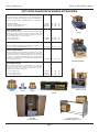
1
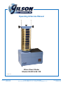
Operating & Service Manual
Gilson Sieve Shaker
Models SS-8R & SS-12R
© Copyright 2008
PHONE: 800-444-1508
740-548-7298
P.O. Box 200, Lewis Center, Ohio 43035-0200
Email: [email protected] Website: www.globalgilson.com
FAX: 800-255-5314
740-548-5314
Gilson Company, Inc.
SS-8R & SS-12R Sieve Shaker
SAFETY INSTRUCTIONS
Safe operation of the Sieve Shaker is your responsibility. You are responsible for operating and maintaining this equipment in compliance with
these instructions and with the use of common sense. You should always
review and completely understand the operating and safety instructions
before using the machine.
DANGER: This machine operates on electric current. Improper operation
could result in electric shock, electrocution, or an explosion.
1. The standard Gilson Sieve Shaker comes with a 1/3-hp motor wired
for 115V, 60Hz. Sieve shakers can also be ordered with special wirings:
230/60, 110/50, and 220/50. Motors are NOT explosion-proof. Always
make sure the motor and electrical components are appropriated for
your intended use and are properly configured.
2. Always check electrical wiring for loose connections and for pinched
or frayed wiring.
3. Always use properly-wired, three-pronged plug, or otherwise ground
the machine. Connect the machine to a properly-wired, three-pronged
receptacle. Make sure the cord is located where no one will trip or get
tangled in it.
4. Always disconnect and lock out power supply before performing maintenance and repairs.
Warning:
Never operate the sieve shaker without having all covers and
case in place.
Warning:
Keep your body away from the unit's moving parts when it is
operating.
Warning:
Always unplug or disconnect machine from the power source
when the unit is not in operation.
Warning:
The electric motor on this machine has internal thermal protection.
If the motor shuts off from overload, the machine may restart by
itself after cooling off, unless the machine is unplugged during
cool-down.
Warning:
Always be sure the machine is level before operation. Re-level
if excessive vibration and machine movement occur.
Warning:
Always wear safety glasses when operating, maintaining, or
repairing this machine.
Gilson Company, Inc.
SS-8R & SS-12R Sieve Shaker
Table of Contents
Safety Instructions
I.
Uncrating & Assembly Instructions
2
II.
Operation
3
III.
Maintenance and Disassembly
4
IV.
Troubleshooting
4
V.
Parts Diagram and List
5-6
Accessories
7-9
VI.
Page 1
Gilson Company, Inc.
SS-8R & SS-12R Sieve Shaker
Models SS-8R and SS-12R
This manual applies to Serial Number SS-1812 and higher. For older units, request manual for your serial
number; or convert to current design by ordering parts numbered 4P through 8P from this manual.
I. Uncrating & Assembly Instructions
1. The SS-8R and SS-12R weigh approximately 135
pounds and 162 pounds, respectively. Use appropriate
equipment and manpower to uncrate the sieve shaker.
Wear safety glasses and work gloves.
2. In most instances, the simplest method of uncrating
is to cut the carton away from the machine. Leave
the carton intact as far as possible so that it can be
used to return the machine if necessary.
3. Lift machine from skids and carton, using appropriate
equipment to lift the machine onto a substantial, solid
work surface.
4. If you are not going to mount the machine to the work
surface, lay the sieve shaker on its side to install of
the leveling legs.
5. Turn the legs into the threaded holes in the bottom
corners of the outer case. Turn the legs all the way
in at this point. Set the sieve shaker upright. Level
the machine by adjusting the legs until the machine
is level and rigid.
Further leveling will likely be required once the sieve
shaker is fully assembled and ready for operation.
Re-level when you move the sieve shaker, when the
material in the sieves does not remain evenly distributed, or when the machine becomes unstable in
operation.
the tops of the clamp rods is equal to the center-tocenter distance between the holes in the clamp bar
tube (4P).
7. Tighten clamp rod nuts (#3). The clamp rod acorn
nuts (#1) will be installed later.
8. Place the cover (#6P) on a temporary work surface
with the sleeve up. Insert the clamp center knob and
washer (#5P) through the sleeve and into threads of
the clamp bar tube (#4P).
9. Loosen end knobs (#7P), remove the wooden dowel
shipping pins at each end of the clamp bar, and place
the cover assembly onto the clamp rods (#2).
10. Position the cover assembly approximately one inch
below threads at top of rods (#2), and clamp in place
by tightening the clamp end knobs (#7P).
11. Screw acorn nuts (#1) onto the tops of the clamp rods
(#2) until secure.
12. Place the Sieve Shaker on a substantial, solid work
surface sufficient to provide support for this size machine.
13. Re-level prior to operating.
6. Mount clamp rods (#2) by turning them into holes in
sieve platform (#9) until they are flush with bottom
of the platform. Make sure that the clamp rods are
parallel to each other and that the distance between
Page 2
Gilson Company, Inc.
SS-8R & SS-12R Sieve Shaker
II. Operation
Read and be sure you understand all safety and operating
instructions, including the separate timer instructions.
The Gilson Sieve Shaker is designed primarily for sieving material particles of a size ranging from No. 4 to
No. 200. Sample quantity should be large enough to be
representative, yet small enough to avoid overloading
any individual sieve. Maximum loading for sieves size
No. 4 and smaller should be about 200g for 8-inch sieves
and about 450g for 12-inch sieves. Sieves larger than No.
4 should be limited to about one particle of material for
each hole available.
The sieve cover and clamping assembly secure sieve
stacks of varying heights. Prepare your sieve stack and
clamp it as follows:
1. Unscrew the clamp center knob (#5P) several complete
turns to provide slack.
2. Place your sieve stack on the sieve platform.
3. Loosen the end knobs (#7P). Apply inward pressure
on the end knobs, while lowering cover assembly until
cover rests evenly on the top sieve. Tighten clamp end
knobs to lock the assembly to the clamp rods (#2).
4. Tighten clamp center knob (#5P) until center screw
pushes cover downward to secure sieve stack in place
vertically.
5. Check to see that the machine is level, and correct the
leveling, if necessary.
6. Lock leveling legs in final position with lock nuts provided. This step should not have to be repeated until
you move the sieve shaker to another substantial solid
work surface, until the sieve shaker becomes unstable in
operation, or until your sample does not remain evenly
dispersed in your top sieve.
7. Connect the three-pronged plug into a 115V, 60Hz
grounded power source.
8. Perform your test. Time required to complete a test
will vary depending upon the physical characteristics of
the test material. Most separations will be complete in
ten minutes or less. Refer to your test specifications,
and be consistent.
9. Disconnect and lock out power to the Sieve Shaker
when it is not in use.
10. The SS-8R and SS-12R Sieve Shakers are equipped
with a tapping mechanism which makes a loud noise.
If the noise is unacceptable, consider using the
SSA-805R Sound Compartment.
Models SS-8R and SS-12R are counterbalanced to permit
free-standing operation with most common sieve loadings. With very tall or very short sieve stacks, the units
may be unstable and move around during operation.
Normally this condition occurs only with sieve stacks
exceeding about 20 inches (508mm) in height. This is
equivalent to using more than eight sieves and pan of
2-1/8 in. stacking height.
If you need to use tall sieve stacks, and your sieve shaker
moves around, try re-leveling. If that does not work, mount
the unit to a solid, substantial table or bench.
NOTE: Bolting the machine down is not a substitute
for leveling. Bolting the shaker down without proper
leveling will cause forces from the unbalanced sieve
stack to damage the drive mechanism. This damage
is not covered by warranty.
1. Disconnect and lock out power supply. Remove the
four threaded leveling legs.
2. Remove left and right case covers, following instructions in disassembly.
3. Obtain four 1/4-in. (6.35mm) diameter bolts with nuts,
flat washers and lock washers. Bolt length will depend
on the thickness of the mounting bench and on the
thickness of the shims which you use to level the Sieve
Shaker prior to mounting. Bolting the machine down
is not a substitute for leveling.
4. The 1/4" diameter bolts will pass through the leveling
leg holes without engaging the threads. If you cannot
reach the internal case corners to tighten the bolts,
remove the entire operating assembly as described
in Disassembly.
Bolt length will depend on thickness of mounting bench.
The 1/4-in. diameter bolts will pass through the leveling leg holes without engaging threads. If you cannot
reach the internal case corners to tighten the bolts,
remove the entire operating assembly as described in
Disassembly.
If stability is a problem with short sieve stacks, add extra
nonfunctional sieves below an extended-rim pan.
When using 8-inch sieves on the Model SS-12R, always use the platform adapter to compensate for the
difference in sieve weights. This adapter can be used
with either a regular or an extended-rim pan. When
the adapter is positioned with larger I.D. side up, you
can use either pan. Invert the adapter for a tighter fit if
using only an extended rim pan. Secure the ring to the
sieve platform with the two cap screws provided.
Page 3
Gilson Company, Inc.
SS-8R & SS-12R Sieve Shaker
III. Maintenance and Disassembly
Before performing maintenance or repairs on the sieve
shaker, always read and understand the safety, operating,
and maintenance instructions.
Please provide the serial number and model number of
the unit when ordering replacement parts.
Routine annual maintenance:
1. Apply of a few drops of oil to the motor end bearings.
2. Inspect the drive belt for wear, tension, and alignment.
A worn, loose, tight, or misaligned drive belt can affect operation of the sieve shaker.
The belt should be snug: neither too tight nor too
loose. A snug fit assures longer life, less bearing wear,
and quieter operation than a belt which is too tight. A
loose drive belt may cause the unit to run too slowly
or in spurts. The drive belt should deflect 1/64 of the
value of the span of the pulleys. The pulleys should
be aligned to avoid excessive edge wear.
Never force or pry the belt over the pulley flanges.
Use disassembly steps 1-3.
Every two years or whenever disassembled:
Grease the thrust bearing (#13) and the face of the cam
(#31). Perform disassembly steps 1-7 to access these
parts.
Disassembly:
the mounting plate (#17), and lift the entire unit out
of its case.
5. Unhook the two hammer springs (#23).
6. Remove the connecting link nuts (#41) and links (#40).
7. Remove the hammer post capscrews (#25), actuator
link screws (#36), bumper block capscrews (#20), and
lock ring (#19). Now you can lift the sieve platform
with main shaft out of its center housing (#15).
8. If you remove the cam shaft hangers (#27) for any reason,
reassemble exactly as removed. The roller clutch block
(#33) and one cam shaft hanger (#27) contain overrunning clutches which must be installed to allow correct
rotation of the cam shaft (#29), or serious damage will
result.
Main bearings have permanent lubrication and are
sealed inside the main housing (#15). This main
housing with bearings and hub should not be disassembled in the field; replace them as a unit if
necessary.
IV. Troubleshooting
1. Unit fails to operate: Check motor, electrical connections, and timer. Replace or reconnect as necessary.
Check drive belt tension; replace belt if worn.
2. Unit runs but fails to give impact tapping: Remove covers, drive belt and mounting capscrews (#16). Replace
or reconnect hammer springs (#23) as required.
1. Disconnect and lock out the power supply.
3. Unit operates but is excessively noisy: Disassemble
through step 4. Check resilient faces on bumper block
(#20) and replace block if necessary.
2. Locate the four cover-mounting screws, and remove
them. Remove right (timer side) section of the cover.
4. Unit is unstable; shakes or walks too much:
Inside the left cover section, locate two more mounting
screws on the cover flanges. Remove these screws
and the left section of the cover.
3. Loosen the four motor mounting bolts. Motor will
slide toward the left side of the machine, loosening
tension on the belt so that you can remove it.
4. Remove the four mounting cap screws (#16) from
Page 4
a. Readjustlevelvia leveling legs, and lock with lock nuts.
b. For Model SS-12R, be sure that weighted platform
adapter is used when using 8-inch diameter sieves.
c. Loosen and re-clamp the sieve stack.
d. Check sieve stack height. If over 20 inches, see
Operation.
Gilson Company, Inc.
SS-8R & SS-12R Sieve Shaker
Page 5
Gilson Company, Inc.
V. Parts
SS-8R & SS-12R Sieve Shaker
No. Req'd Key No.
No. Req'd Key No.
Sieve Clamping Parts
Clamp Rod acorn nut
Clamp rod*
Clamp rod nut
Clamp bar tube
Clamp center knob
with screw & washer
Clamp compression sleeve
with cover
Clamp end knob
with washer and cap
Clamp bar block
Cam Shaft Assembly Parts
2
2*
2
1
1
2*
3
4P
1
5P
1
6P
2
2
7P
8P
Cam shaft hanger
Hanger capscrew
& lock washer
Cam shaft
Cam shaft hanger bushing
Cam
Roller clutch
Roller clutch block
Cam shaft spacer
Cam shaft nylon washers
Actuator link
with rod ends (2)
and nuts (2)
Actuator link screw
Stabilizer rocker bracket
Stabilizer rocker bracket
nylon bushing
Stabilizer rocker bracket
bolt & nut
Connecting link
Connecting link nut
Connecting link washer
Connecting link rubber bushing
Stabilizer arm
*Note: Serial No. SS-1529 and lower have 23-1/4"
long Clamp Rods. Longer 27-1/16" rods
as currently used may be substituted but
must be replaced as a pair.
Main Shaft Parts
Sieve platform
with main shaft
Drive pulley & counterweight
with key and setscrew
Neoprene sponge washer
Anti-friction washer
Thrust bearing
Nonmetallic bushing
Main housing
with bearings & hub
Mounting capscrew
with lock washer
Mounting plate
Lower counterweight
with key & setscrew
Lock ring
Bumper block
with capscrews (2)
and lock washers (2)
1
9
1
1
1
1
2
10
11
12
13
14
1
15
8
1
16
17
1
1
18
19
1
20
1
1
2
2
2
21
22
23
24
25
4
26
27
4
1
1
1
2
1
1
4
28
29
30
31
32
33
34
34A
1
2
1
35
36
37
2
38
2
2
4
4
4
1
39
40
41
42
43
44
1
1
—
—
1
4
4
—
—
—
1
1
—
—
1
1
1
1
1
—
—
—
—
—
Outer Case Parts
Outer case
Left case cover
Right case cover (including
pad on Model SS-8R)
Cover mounting screw
Leveling leg with lock nut
Electric and Driving Parts
Motor, 1/3-hp, 110V, 60Hz
Motor cord, grommet & plug
Motor mounting bolt with nut,
flat washer and lock washer
Motor pulley
Drive belt
Timer with screws (2)
Timer cord
Hammer Assembly Parts
Upper hammer
Lower hammer
Hammer spring
Hammer post
Hammer post capscrew
Hammer post
nonmetallic bushing
2
Page 6
Gilson Company, Inc.
SS-8R & SS-12R Sieve Shaker
ROUND TEST SIEVES
8" Diameter ROUND TEST SIEVES
Brass Cloth
Brass Frame
Certificate of
Compliance for All Sieves
HOW TO ORDER SIEVES
Sieves may be ordered either by individual
model numbers from the tables on
following pages or by description.
Ordering by description is convenient
when several sieves on an order are of
same configuration, differing only by
U.S. Standard size designation. Example:
8" diameter, full-height, all brass sieves in
sizes 3/4", #4, #8, #30, #100, regular pan.
When ordering by description, all of the
following must be specified:
1. Diameter:
available)
8" (3", 6", 10", 12" also
2. Metallic Construction: B (brass cloth,
brass frame), C (stainless cloth, brass
frame), or S (stainless cloth, stainless
frame).
3. Stacking Height: Full or Half
(also intermediate for 12")
4. US Standard size designations:
(or mm and µm designations)
Refer to sieve model number tables
to be sure that sieves are offered in
configurations you order.
PRICES
As the world's largest source of test
screening and sieving instruments,
Gilson is able to offer top quality sieves
manufactured to ASTM E 11 standards at
the best possible pricing.
CUSTOM SIEVES
Examples of custom sieves that may
be ordered from Gilson: brass frame 5"
(127mm) diameter; 8" diameter all brass
round and square hole punched plate.
Inquire for your special needs.
Stainless Cloth
Brass Frame
Coarse Series
Full Ht.
Half Ht.
Full Ht.
Half Ht.
4"
100mm
3-1/2"
90mm
3"
75mm
2-1/2"
63mm
2.12"
53mm
2"
50mm
1-3/4"
45mm
1-1/2"
37.5mm
1-1/4"
31.5mm
1.06"
26.5mm
1"
25.0mm
7/8"
22.4mm
3/4"
19.0mm
5/8"
16.0mm
0.530"
13.2mm
1/2"
12.5mm
7/16"
11.2mm
3/8"
9.5mm
5/16"
8.0mm
0.265"
6.7mm
1/4"
6.3mm
No. 3-1/2
5.6mm
No.4
4.75mm
Fine Series
—
—
—
—
—
—
—
—
—
—
—
—
—
—
—
—
—
—
—
—
—
V8BF#003
V8BF#004
—
—
—
—
—
—
—
—
—
—
—
—
—
—
—
—
—
—
—
—
—
V8BH#003
V8BH#004
V8CF"400
—
V8CF"350
—
V8CF"300
—
V8CF"250
—
V8CF"212
—
V8CF"200
—
V8CF"175
—
V8CF"150
—
V8CF"125
—
V8CF"106
—
V8CF"100
—
V8CF"088
—
V8CF"075
—
V8CF"063
—
V8CF"053
—
V8CF"050
—
V8CF"044
—
V8CF"038
—
V8CF"031
—
V8CF"027
—
V8CF"025 V8CH"025
V8CF#003 V8CH#003
V8CF#004 V8CH#004
V8SF"400
V8SF"350
V8SF"300
V8SF"250
V8SF"212
V8SF"200
V8SF"175
V8SF"150
V8SF"125
V8SF"106
V8SF"100
V8SF"088
V8SF"075
V8SF"063
V8SF"053
V8SF"050
V8SF"044
V8SF"038
V8SF"031
V8SF"027
V8SF"025
V8SF#003
V8SF#004
—
—
—
—
—
—
—
—
—
—
—
—
—
—
—
—
—
—
—
—
V8SH"025
V8SH#003
V8SH#004
No.5
4.00mm
No.6
3.35mm
No.7
2.80mm
No.8
2.36mm
No.10
2.00mm
No.12
1.70mm
No.14
1.40mm
No.16
1.18mm
No.18
1.00mm
No.20
850µm
No.25
710µm
No.30
600µm
No.35
500µm
No.40
425µm
No.45
355µm
No.50
300µm
No.60
250µm
No.70
212µm
No.80
180µm
No.100
150µm
No.120
125µm
No.140
106µm
No.170
90µm
No.200
75µm
No.230
63µm
No.270
53µm
No.325
45µm
No.400
38µm
No.450
32µm
No.500
25µm
No.635
20µm
Regular Pan
Extended Rim Pan
Regular Cover
Cover with Ring
V8BF#005 V8BH#005
V8BF#006 V8BH#006
V8BF#007 V8BH#007
V8BF#008 V8BH#008
V8BF#010 V8BH#010
V8BF#012 V8BH#012
V8BF#014 V8BH#014
V8BF#016 V8BH#016
V8BF#018 V8BH#018
V8BF#020 V8BH#020
V8BF#025 V8BH#025
V8BF#030 V8BH#030
V8BF#035 V8BH#035
V8BF#040 V8BH#040
V8BF#045 V8BH#045
V8BF#050 V8BH#050
V8BF#060 V8BH#060
V8BF#070 V8BH#070
V8BF#080 V8BH#080
V8BF#100 V8BH#100
V8BF#120 V8BH#120
V8BF#140 V8BH#140
V8BF#170 V8BH#170
V8BF#200 V8BH#200
V8BF#230 V8BH#230
V8BF#270 V8BH#270
V8BF#325 V8BH#325
V8BF#400 V8BH#400
—
—
—
—
—
—
V8BFXPN
V8BHXPN
V8BFXPE
V8BHXPE
V8BFXCV
V8BFXCR
V8CF#005 V8CH#005
V8CF#006 V8CH#006
V8CF#007 V8CH#007
V8CF#008 V8CH#008
V8CF#010 V8CH#010
V8CF#012 V8CH#012
V8CF#014 V8CH#014
V8CF#016 V8CH#016
V8CF#018 V8CH#018
V8CF#020 V8CH#020
V8CF#025 V8CH#025
V8CF#030 V8CH#030
V8CF#035 V8CH#035
V8CF#040 V8CH#040
V8CF#045 V8CH#045
V8CF#050 V8CH#050
V8CF#060 V8CH#060
V8CF#070 V8CH#070
V8CF#080 V8CH#080
V8CF#100 V8CH#100
V8CF#120 V8CH#120
V8CF#140 V8CH#140
V8CF#170 V8CH#170
V8CF#200 V8CH#200
V8CF#230 V8CH#230
V8CF#270 V8CH#270
V8CF#325 V8CH#325
V8CF#400 V8CH#400
V8CF#450 V8CH#450
V8CF#500 V8CH#500
V8CF#635 V8CH#635
V8BFXPN V8BHXPN
V8BFXPE V8BHXPE
V8BFXCV
V8BFXCR
V8SF#005 V8SH#005
V8SF#006 V8SH#006
V8SF#007 V8SH#007
V8SF#008 V8SH#008
V8SF#010 V8SH#010
V8SF#012 V8SH#012
V8SF#014 V8SH#014
V8SF#016 V8SH#016
V8SF#018 V8SH#018
V8SF#020 V8SH#020
V8SF#025 V8SH#025
V8SF#030 V8SH#030
V8SF#035 V8SH#035
V8SF#040 V8SH#040
V8SF#045 V8SH#045
V8SF#050 V8SH#050
V8SF#060 V8SH#060
V8SF#070 V8SH#070
V8SF#080 V8SH#080
V8SF#100 V8SH#100
V8SF#120 V8SH#120
V8SF#140 V8SH#140
V8SF#170 V8SH#170
V8SF#200 V8SH#200
V8SF#230 V8SH#230
V8SF#270 V8SH#270
V8SF#325 V8SH#325
V8SF#400 V8SH#400
V8SF#450 V8SH#450
V8SF#500 V8SH#500
V8SF#635 V8SH#635
V8SFXPN V8SHXPN
V8SFXPE V8SHXPE
V8SFXCV
V8SFXCR
Page 7
Full Ht.
Half Ht.
Stainless Cloth
Stainless Frame
Gilson Company, Inc.
SS-8R & SS-12R Sieve Shaker
12-INCH ROUND TEST SIEVES
Gilson Offers
3 Stacking
Heights
For 12" Sieves:
For handling
convenience,
Intermediate
Height is
recommended for
most applications.
Full Height
Intermediate Height
Half Height
12" Diameter ROUND TEST SIEVES
Brass Cloth
Brass Frame
Coarse
4"
3-1/2"
3"
2-1/2"
2.12"
2"
1-3/4"
1-1/2"
1-1/4"
1.06"
1"
7/8"
3/4"
5/8"
0.530"
1/2"
7/16"
3/8"
5/16"
0.265"
1/4"
No. 3-1/2
No.4
Series
100mm
90mm
75mm
63mm
53mm
50mm
45mm
37.5mm
31.5mm
26.5mm
25.0mm
22.4mm
19.0mm
16.0mm
13.2mm
12.5mm
11.2mm
9.5mm
8.0mm
6.7mm
6.3mm
5.6mm
4.75mm
Stainless Cloth
Brass Frame
Stainless Cloth
Stainless Frame
Full Ht.
Inter Ht.
Half Ht.
Full Ht.
Inter Ht.
Half Ht.
Full Ht.
Inter. Ht.
Half Ht.
—
—
—
—
—
—
—
—
—
—
—
—
—
—
—
—
—
—
—
—
—
—
—
—
—
—
—
—
—
—
—
—
—
—
—
—
—
—
—
—
—
—
—
—
—
—
—
—
—
—
—
—
—
—
—
—
—
—
—
—
—
—
—
—
—
—
—
—
—
V12CF"400
V12CF"350
V12CF"300
V12CF"250
V12CF"212
V12CF"200
V12CF"175
V12CF"150
V12CF"125
V12CF"106
V12CF"100
V12CF"088
V12CF"075
V12CF"063
V12CF"053
V12CF"050
V12CF"044
V12CF"038
V12CF"031
V12CF"027
V12CF"025
V12CF#003
V12CF#004
V12CI"400
V12CI"350
V12CI"300
V12CI"250
V12CI"212
V12CI"200
V12CI"175
V12CI"150
V12CI"125
V12CI"106
V12CI"100
V12CI"088
V12CI"075
V12CI"063
V12CI"053
V12CI"050
V12CI"044
V12CI"038
V12CI"031
V12CI"027
V12CI"025
V12CI#003
V12CI#004
V12CH"400
V12CH"350
V12CH"300
V12CH"250
V12CH"212
V12CH"200
V12CH"175
V12CH"150
V12CH"125
V12CH"106
V12CH"100
V12CH"088
V12CH"075
V12CH"063
V12CH"053
V12CH"050
V12CH"044
V12CH"038
V12CH"031
V12CH"027
V12CH"025
V12CH#003
V12CH#004
V12SF"400
V12SF"350
V12SF"300
V12SF"250
V12SF"212
V12SF"200
V12SF"175
V12SF"150
V12SF"125
V12SF"106
V12SF"100
V12SF"088
V12SF"075
V12SF"063
V12SF"053
V12SF"050
V12SF"044
V12SF"038
V12SF"031
V12SF"027
V12SF"025
V12SF#003
V12SF#004
V12SI"400
V12SI"350
V12SI"300
V12SI"250
V12SI"212
V12SI"200
V12SI"175
V12SI"150
V12SI"125
V12SI"106
V12SI"100
V12SI"088
V12SI"075
V12SI"063
V12SI"053
V12SI"050
V12SI"044
V12SI"038
V12SI"031
V12SI"027
V12SI"025
V12SI#003
V12SI#004
V12SH"400
V12SH"350
V12SH"300
V12SH"250
V12SH"212
V12SH"200
V12SH"175
V12SH"150
V12SH"125
V12SH"106
V12SH"100
V12SH"088
V12SH"075
V12SH"063
V12SH"053
V12SH"050
V12SH"044
V12SH"038
V12SH"031
V12SH"027
V12SH"025
V12SH#003
V12SH#004
—
—
—
V12BF#008
V12BF#010
V12BF#012
V12BF#014
V12BF#016
V12BF#018
V12BF#020
V12BF#025
V12BF#030
V12BF#035
V12BF#040
V12BF#045
V12BF#050
V12BF#060
V12BF#070
V12BF#080
V12BF#100
V12BF#120
V12BF#140
V12BF#170
V12BF#200
V12BF#230
V12BF#270
V12BF#325
—
—
—
—
V12BFXPN
V12BFXPE
—
—
—
V12BI#008
V12BI#010
V12BI#012
V12BI#014
V12BI#016
V12BI#018
V12BI#020
V12BI#025
V12BI#030
V12BI#035
V12BI#040
V12BI#045
V12BI#050
V12BI#060
V12BI#070
V12BI#080
V12BI#100
V12BI#120
V12BI#140
V12BI#170
V12BI#200
V12BI#230
V12BI#270
V12BI#325
V12BI#400
—
—
—
V12BIXPN
V12BIXPE
V12BFXCV
V12BFXCR
—
—
—
V12BH#008
V12BH#010
V12BH#012
V12BH#014
V12BH#016
V12BH#018
V12BH#020
V12BH#025
V12BH#030
V12BH#035
V12BH#040
V12BH#045
V12BH#050
V12BH#060
V12BH#070
V12BH#080
V12BH#100
V12BH#120
V12BH#140
V12BH#170
V12BH#200
V12BH#230
V12BH#270
V12BH#325
V12BH#400
—
—
—
V12BHXPN
V12BHXPE
V12CF#005
V12CF#006
V12CF#007
V12CF#008
V12CF#010
V12CF#012
V12CF#014
V12CF#016
V12CF#018
V12CF#020
V12CF#025
V12CF#030
V12CF#035
V12CF#040
V12CF#045
V12CF#050
V12CF#060
V12CF#070
V12CF#080
V12CF#100
V12CF#120
V12CF#140
V12CF#170
V12CF#200
V12CF#230
V12CF#270
V12CF#325
V12CF#400
V12CF#450
V12CF#500
V12CF#635
V12BFXPN
V12BFXPE
V12CI#005
V12CI#006
V12CI#007
V12CI#008
V12CI#010
V12CI#012
V12CI#014
V12CI#016
V12CI#018
V12CI#020
V12CI#025
V12CI#030
V12CI#035
V12CI#040
V12CI#045
V12CI#050
V12CI#060
V12CI#070
V12CI#080
V12CI#100
V12CI#120
V12CI#140
V12CI#170
V12CI#200
V12CI#230
V12CI#270
V12CI#325
V12CI#400
V12CI#450
V12CI#500
V12CI#635
V12BIXPN
V12BIXPE
V12BFXCV
V12BFXCR
V12CH#005
V12CH#006
V12CH#007
V12CH#008
V12CH#010
V12CH#012
V12CH#014
V12CH#016
V12CH#018
V12CH#020
V12CH#025
V12CH#030
V12CH#035
V12CH#040
V12CH#045
V12CH#050
V12CH#060
V12CH#070
V12CH#080
V12CH#100
V12CH#120
V12CH#140
V12CH#170
V12CH#200
V12CH#230
V12CH#270
V12CH#325
V12CH#400
V12CH#450
V12CH#500
V12CH#635
V12BHXPN
V12BHXPE
V12SF#005
V12SF#006
V12SF#007
V12SF#008
V12SF#010
V12SF#012
V12SF#014
V12SF#016
V12SF#018
V12SF#020
V12SF#025
V12SF#030
V12SF#035
V12SF#040
V12SF#045
V12SF#050
V12SF#060
V12SF#070
V12SF#080
V12SF#100
V12SF#120
V12SF#140
V12SF#170
V12SF#200
V12SF#230
V12SF#270
V12SF#325
V12SF#400
V12SF#450
V12SF#500
V12SF#635
V12SFXPN
V12SFXPE
V12SI#005
V12SI#006
V12SI#007
V12SI#008
V12SI#010
V12SI#012
V12SI#014
V12SI#016
V12SI#018
V12SI#020
V12SI#025
V12SI#030
V12SI#035
V12SI#040
V12SI#045
V12SI#050
V12SI#060
V12SI#070
V12SI#080
V12SI#100
V12SI#120
V12SI#140
V12SI#170
V12SI#200
V12SI#230
V12SI#270
V12SI#325
V12SI#400
V12SI#450
V12SI#500
V12SI#635
V12SIXPN
V12SIXPE
V12SFXCV
V12SFXCR
V12SH#005
V12SH#006
V12SH#007
V12SH#008
V12SH#010
V12SH#012
V12SH#014
V12SH#016
V12SH#018
V12SH#020
V12SH#025
V12SH#030
V12SH#035
V12SH#040
V12SH#045
V12SH#050
V12SH#060
V12SH#070
V12SH#080
V12SH#100
V12SH#120
V12SH#140
V12SH#170
V12SH#200
V12SH#230
V12SH#270
V12SH#325
V12SH#400
V12SH#450
V12SH#500
V12SH#635
V12SHXPN
V12SHXPE
Fine Series
No.5
4.00mm
No.6
3.35mm
No.7
2.80mm
No.8
2.36mm
No.10
2.00mm
No.12
1.70mm
No.14
1.40mm
No.16
1.18mm
No.18
1.00mm
No.20
850µm
No.25
710µm
No.30
600µm
No.35
500µm
No.40
425µm
No.45
355µm
No.50
300µm
No.60
250µm
No.70
212µm
No.80
180µm
No.100
150µm
No.120
125µm
No.140
106µm
No.170
90µm
No.200
75µm
No.230
63µm
No.270
53µm
No.325
45µm
No.400
38µm
No.450
32µm
No.500
25µm
No.635
20µm
Regular Pan
Extended Rim Pan
Regular Cover
Cover with Ring
Backing Cloth
Brass or stainless steel rolled backing cloth can be added to any sieve to increase support to fine mesh. Backing is recommended in large diameter
sieves to prevent sagging and tearing at the frame joint—especially if the application calls for overloading, or if sample material is abrasive or of high
specific gravity. Unsatisfactory sieve life would suggest replacing with a sieve with backing cloth. (See Table for Model numbers of added backing
cloth.) Sieves with backing cloth are made to order, so deliveries are longer and sieves are nonreturnable.
Models for Added
Rolled Backing Cloth Sieve Support
Sieve
Diameter
8" (203mm)
10" (254mm)
12" (305mm)
Brass
Cloth
SV8-BRB
SV10-BRB
SV12-BRB
Stainless
Cloth
SV8-SRB
SV10-SRB
SV12-SRB
Sieve Diameter
& Height Designation
Height, In.*
Stacked Overall
Shipping Data
lb (kg)
Cu. Ft.
3" (75mm)
FH
HH
1-1/8
5/8
1-1/2
1-1/8
0.5 (0.2)
0.5 (0.2)
0.05
0.05
6" (152mm) FH
HH
1-7/8
1-1/8
2-5/8
1-7/8
1.0 (0.5)
1.0 (0.5)
0.12
0.12
8" (203mm) FH
HH
2-1/8
1-1/8
2-7/8
1-7/8
1.4 (0.6)
1.2 (0.5)
0.16
0.14
10" (254mm) FH
3-1/8
4
2.7 (1.2)
0.45
12" (305mm) FH
IH
HH
3-3/8
2-1/8
1-3/4
4-1/4
2-7/8
2-5/8
3.8 (1.7)
3.0 (1.4)
2.5 (1.1)
0.55
0.55
0.55
*Heights are approximate and vary due to mesh thickness.
Page 8
Gilson Company, Inc.
SS-8R & SS-12R Sieve Shaker
Exclusive Gilson Sieve Shaker Accessories
CLEAN-N-STOR UNITS
Clean-n-Stor units are offered in three versions as handy timesaving aids for repetitive sieve emptying, cleaning, and weighing operations associated with 8" or 200mm diam. sieve testing work.
Stand-alone Model
Model for SS-8R (Bolts to case top)
Model for Electronic Balances
SSA-802
SSA-801
OBA-15R
10
10
13
(4.5)
(4.5)
(5.9)
0.4
1.0
1.0
SIEVE STORAGE RACK
Adjustable freestanding bench rack SSA-803 holds all diameters
of sieves to 12" and is ideal for storing up to 16 Full or Half-Height
8" and 200mm diameter sieves. Order extra support rod set to
increase capacity 50% to 2 rows if needed.
Sieve Storage Rack
Extra Support Rod Set
SSA-802
SSA-803
SSA-804
8.0 (3.6)
1.3 (0.6)
0.3
0.1
SSA-820
26 (11.8)
0.6
SSA-805R
75
WALL MOUNT RACK
Gilson SSA-820 Sieve Rack Unit is for wall-mounted storage of up
to 11 FH or 22 HH 8" (200mm) diameter sieves.
SOUND COMPARTMENTS
Model SSA-805R Sound Compartment is designed for use with
SS-8R and SS-12R Sieve Shakers. Construction is sturdy painted
steel with 1" (25mm) of sound deadening foam. Doors are hinged
for easy access, and two 3.25" (83mm) knockout ports are provided
for hook up of exhaust systems for applications with machines
generating airborne dust.
(34) 17.0
OBA-15R with balance
PLATFORM ADAPTERS
Gilson Platform Adapters are weighted for use with SS8R and 12R Sieve Shakers which require certain loading
for proper operation of machine counterbalance feature.
SSA-812 is for 12" sieve shakers only.
For 3" or 75mm sieves
For 6" or 150mm sieves
For 10" or 250mm sieves
SSA-812
SSA-810
SSA-810
SSA-811
SSA-812
11
8
5
(5.0)
(3.6)
(2.3)
0.2
0.1
0.2
SSA-801 on SS-8R
SSA-811
SSA-820
SSA-803 shown with
SSA-804 Extra Support Rod Set
SSA-805R
shown with SS-8R
Page 9