1
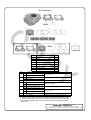
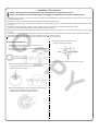
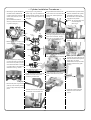
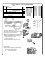
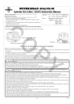
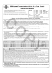
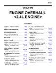
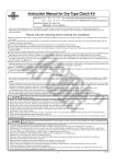
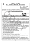
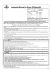
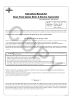
Instruction Manual for / Cylinder Kit
CO
For exclusive use in Super Head+R
Item No.: 01−04−0104 (124 cc)
01−04−0105 (138 cc)
・Thank you for purchasing one of Takegawa’s products.
・This is a piston and cylinder kit for exclusive use in Super Head+R of Takegawa’s make. You are kindly requested to observe the following in using and
installing the kit.
・We have given ceramic composite plating treatment to an aluminum sleeve of the cylinder, which has improved durability and abrasion-resistance compared with the conventional cast-iron sleeves. Moreover, we have successfully designed the piston clearance to be less and reduced the friction loss. The piston is also designed to be light-weight, and the molybdenum coating is applied to the piston skirt, which makes easier the insertion of the piston
into the cylinder.
◎ Please note that, in some cases, the illustrations and photos may vary from the actual hardware.
Please read the following before installation.
!Points to notice about sounds!
After installing this product, in some cases a cooling fin in the cylinder may resonate, making a sound. In this case, as a measure, fix a damper included
in the kit to the cooling fin of the cylinder.
PY
◎ We do not take any responsibility for any accident or damage whatsoever arising from the use of the products not in conformity with the instructions in
the manual.
◎ We shall be held free from any kind of warranty whatsoever of products other than this product if the glitch takes place on the other products than
this one after the installation and use of this product.
◎ If you make modifications to the products, we shall be held free from any guarantee of the products.
◎ This kit is for exlusive use in Super Head+R of our own make.
◎ A cylinder included in this kit may interfere with crankcases depending on individual differences of the stock crankcases. If there is interference, the crankcase needs processing.
◎ Processing of stock crankcases requires detachment and reinstallation of an engine and separation of crankcases. Please do the work correctly referring to HONDA’s genuine service manual. And the assembly and installation need gaskets, etc. additionally, which please purchase separately.
◎ Please be informed that we shall be held harmless against any claim against us whatsoever arising out of use of the products in racing and the like.
The following show the envisioned possibility of injuries to human bodies or property damage as a result of disregarding the following
Caution cautions.
・This product is designed for exclusive use on the closed course. So, take note that it is prohibited to drive your motorcycle on a public road after
installation of this kit. Drive your motorcycle at a legal speed, abiding by the laws.
・Work only when the engine and the muffler are cool. (Otherwise, you will burn yourself.)
・Prepare right tools for the work. (Otherwise, improper work could cause breakage of parts or injuries to yourself.)
・As some products and frames have sharp edges or protruding portions, please work with utmost care. (Otherwise, you will suffer injuries.)
The following show the envisioned possibility of human death or serious injuries to human bodies as a result of disregarding the
Warning following cautions.
・Those who are technically unskilled or inexperienced are required not to do the work. (Improper installation because of insufficient skill and knowledge could lead to parts breakage and subsequently to accidents.)
・Always use new pinston pin circlips, gaskets, packings and the like. Worn or damaged ones may cause accidents because of breakage of these
parts.
・Before doing work, make sure your bike is secure on level ground for the sake of safe work. (Otherwise, your motorcycle could overturn and
injure you while you are working.)
・If you find damaged parts when checking and performing maintenance of your motorcycle, do not use these parts any longer, and replace them with new ones. The continued use of these damaged parts could lead to an accident.)
・Always start the engine in a well-ventilated place, and do not turn the engine on in an airtight place.
(Otherwise, you will suffer from carbon monoxide poisoning.)
・Before riding, always check every section for slack in parts like screws. If you find slack ones, screw them securely up to the specified torque.
(Or improper torque may cause parts to come off, leading to accidents.)
・When you notice something abnormal with your motorcycle while riding, stop riding immediately and park your motorcyle in a safe place.
(Otherwise, the abnormality could lead to accidents.) (Otherwise, the continued ride could lead to accidents.)
・As gasoline is highly flammable, never place it close to fire. Make sure that nothing flammable is near the gasoline. (It may cause a fire.)
・Check or perform maintenance of parts correctly according to the procedures in the instruction manual or a service manual.
(Improper checking or maintenance could lead to accidents.)
・Never use parts other than those specified by us. (Or, the unspecified parts may break, leading to accidents.)
・Tighten parts securely using a torque wrench to the specified torque. (Otherwise, bolts and nuts may break or come off, causing accidents.)
・Since vaporized accumulation of gasoline is quite dangerous, work in a well-ventilated place. (It is at the high risk of explosion.)
・Be sure to always use premium unleaded petrol. (Otherwise, troubles such as knocking of an engine may cause accidents.)
◎ Please be informed that the product specifications, design and prices are subject to change without prior notice.
◎Please be informed that we do not accept any complaint filed with us against any technical trouble caused by the combined use of our products with other
manufacturers' products unspecified by us.
◎ Please retain this Instruction Manual for future reference.
-1-
Apr./11/’
06
∼ Kit Contents ∼
1
6
CO
7
4
2
5
3
8
A
No.
1
2
3
4
5
6
7
8
B
56
59
124
138
C
1
2
3
4
8
PY
Part Name
Aluminum cylinder
Piston
Piston ring set (top, 2nd, oil)
Piston pin
Piston pin circlips
Cylinder head gasket
Cylinder gasket
Cylinder dampers B
Repair Parts Item No.
No.
A
B
56
59
56
59
56
59
01-13-0102
01-13-0103
01-02-0101
01-02-0102
000-02-120
01-01-0101
01-01-0102
13108-KSH-T00 (for 124 cc)
13110-KSH-T00 (for 138 cc)
01-05-020
01-15-023
000-02-102
000-03-048
C
Qty
1
1
1
1
2
1
1
19
Part Name
Gasket kit B
Piston kit
Piston pin circlip set (consisting of 6 pcs)
Aluminum cylinder
Piston
Piston ring set
Piston pin
Cylinder damper B (consisting of 10 pcs)
∴In placing a repair parts order with us, please quote the Repair Parts Item Nos.
In some cases, however, we may not be able to accept your orders for a single
item of the assembled unit. In this case, please order the required parts in the
unit of a set.
Co.,Ltd.
3-5-16 Nishikiorihigashi Tondabayashi Osaka Japan
TEL : 81-721-25-1357 FAX : 81-721-24-5059 URL : http://www.takegawa.co.jp
-2-
Apr./11/’
06
∼ Installation Procedures ∼
Caution: Always be sure to tighten parts to the specified torque using a torque wrench.
Notice: The unskilled or those without proper knowledge are requested not to do the installation work.
○ Installation of this kit requires, in some cases, engine removal and crankcase disassembly. Please prepare and refer to a genuine service manual to do
the proper installation work.
○ According to the service manual, demount the engine from the frame and and disassemble it.
○ A crankcase may interfere with a cylinder sleeve depending on individual differences of the crankcases. If there is interference, the crankcase needs
processing.
○ Setting the cylinder in place with a dowel pin, attach it to the crankcase, and check for the interference with the crank cases.
○ In case there is interference, see where the cylinder interferes with the crankcases.
○Referring to the service manual, disassemble the crankcases, and scrape the interferring part with a file or a hand grinder but bit by bit not to over-scrape
the portion.
CO
○ In scraping, be careful not to let the cutting chips and shavings into bearings and other parts. After the processing of the crankcases, clean them.
○ After disassembling the crankcases, check every component referring to the service manual.
Caution: Do inspection of every component and replacement of consumables, with utmost care.
・Measure the deflection of the crank shaft.
∴ If larger than 0.08 mm, replace it.
Inspection of Crank Shaft
・Measure the internal diameter at the small end of the con’rod.
∴ If larger than 13.05 mm, replace it.
・Measure the clearance at the big end of the con’rod in the axial direction.
∴ If larger than 0.4mm, replace it.
PY
7mm
7mm
o Assemble the crank case referring to the service manual.
・Measure the misalignment at two points at the big end of the con’rod at
right angles to the shaft as shown in the figure on the right.
∴ If larger than 0.07mm, replace it.
Y
X
・Measure the misalignment on the journal bearing of the crank shaft.
∴ Shaft direction:If larger than 0.10 mm, replace it.
Bearing direction: If larger than 0.05 mm, replace it.
-B1-
Apr./11/’
06
∼ Cylinder Installation Procedures ∼
○ Securely fix cylinder dampers B,
included in the kit, between the cylinder cooling fins until they hit
a dead end as shown in the ○ Apply engine oil to grooves for
piston rings, and, with reference to
the figure below, fix piston rings and
arrange the location of piston ring
end gaps.
CO
figure below.
(This installation is aimed at
reducing a resonant sound from
a cylinder cooling fin.)
Top ring
(Brown)
Second ring
(Black)
Expander
Piston
○Attach the piston pin circlip so the
ring end gap does not meet with
the notch on the piston pin hole,
and it should be either on the top
or at the bottom of the piston as
illustrated in the fig. 1 below.
○Remove the cloth used to plug holes.
Mark
○ Thoroughly degrease the cylinder
base of the crankcase, and fit a dowel pin into the dowel pin hole.
PY
○ Fix a cylinder gasket of the kit into
the cylinder base of the crankcase. ※Installing the chain guide on
cylinder, the chain guide may not
reach at the bottom of the groove.
In that case, you need a modification as the photo shown
below to install the chain guide properly.
Second ring
Side rails
Expander
○Attach the cam chain guide to the
cylinder.
Side rail
Top ring
Piston
○Put the aluminum cylinder into the
stud bolt, and attach the cylinder,
compressing the piston rings.
Be careful not to move the piston
ring gaps out of position.
Caution: Do the work with care
not to damage the
piston rings.
Mark
○ Attach a piston pin circlip to one
of two pin holes on the piston.
○Plug the sleeve hole and the cam chain hole on the crank case with a
clean cloth, and fix a piston pin circlip.
Pay attention to the cross
section as well!!
○ Apply molybdenum solution to the
piston pin and the holes on the
connecting rod small end.
End gaps
○ Apply engine oil to the entire inner
surface of the aluminum cylinder bore.
Grind here
○ Air-blow the piston rings and the
piston pin, and check for jamming
of any foreign material by these
parts.
○ Attach the piston to the connecting
rod with an arrow on the piston in
the direction of the exhaust side.
-B2-
○ Install the cylinder head with
reference to the instruction manual.
Apr./11/’
06
Reference Value List for Cylinder and Piston Maintenance
Item
Stock
Cylinder Distortion
Internal diameter
φ56
φ59
External diamter(7.5 mm from the hem of a skirt) φ56
(7.5 mm from the hem of a skirt) φ59
Internal diameter of a pin hole
External diameter of a piston pin
Piston ring end gap size
Top
2nd
Oil
Clearance between cylinder and piston
Clearance between piston and pin
CO
Piston
○ Inspection of Cylinder
・Check the inside of cylinder for wear and damage.
・Measure the internal diameters of the cylinder bore at 6 positions; at the
piston pin angle and at the right angle to it (X-Y) each at upper, middle and
lower parts of the cylinder bore.
Treat the largest value as its internal diameter.
∴ If larger than 56.05mm at φ 56, replace it.
If larger than 59.05mm at φ 59, replace it.
56.000∼56.015mm
59.000∼59.015mm
55.965∼55.985mm
58.965∼58.985mm
13.002∼13.008 mm
12.994∼13.000 mm
0.15∼0.38 mm
0.20∼0.45 mm
0.20∼0.70 mm
0.002∼0.014 mm
PY
Service limit
0.05 mm
56.05mm
59.05mm
55.95mm
58.95mm
13.03 mm
12.98 mm
0.50 mm
0.50 mm
0.90 mm
0.12 mm
0.05 mm
IN
upper
Y
Remarks
Replace
Replace
Replace
Replace
Replace
Replace
Replace
Replace
Replace
Replace
Replace
Replace
EX
X
middle
lower
Calculate the clearance between a cylinder and a piston.
○ Inspection of Piston
・Clear the piston of the remaining carbon residue.
・Fit a piston ring into the piston, and measure the clearance between the
piston ring and ring groove with a thickness gauge.
∴ If larger than 0.17mm, replace it.
・Check the piston for damages.
・Measure the external diameter of the piston at the specified place at the
bottom edge of the piston skirt at the right angle to the piston holes.
∴ If smaller than 55.95mm at φ 56, replace it. If smaller than 58.95mm at φ 59, replace it.
・Measure the internal diameter of the piston pin hole.
∴ If larger than 13.03mm, replace it.
・Calculate the clearance between the piston and the piston pin.
○ Inspection of Piston Ring
・Press down a piston ring into the piston with the piston head, and
measure the clearance of the ring-end gap at the horizontal position with
a thickness gauge.
∴Top and 2nd : If larger than 0.5mm, replace them.
Oil
: If larger than 0.9mm, replace it.
-C1-
Apr./11/’
06