1
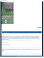
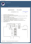
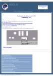
KB2LJJ Radio Mods Database
KB2LJJ
www.r6-ru4montesecchieta.it
IZ5CCV
Home
Radio Mods Database and Manuals
Modifications for the Icom IC-746-74
IC-746 out of range TX/RX
IC-746 Modification
Extended RX/TX for IC-746
Separating the Tx and Rx lines
Power mod for the IC-746
Solutions for chip blowing with
mPC
IC-746 out of range TX/RX
In IC746DW.JPG you can see the open bottom side from the transceiver and you will see a red marked area, too.
This marked area you can see again and bigger in the picture IC746SMD.JPG.
Now something about IC746SMD.JPG.
There are some green frames. This are diodes which must be on this place.
There are some red frames. This are diodes which you have to remove. Where no frame is, there is no diode in my
transceiver.
After removing the red marked diodes you should can
RX 60 khz - 60 MHz and 118 Mhz - 176 MHz
TX 100 khz - 60 MHz and 118 Mhz - 176 MHz
http://www.kb2ljj.com/data/icom/ic-746.htm (1 di 12)23/08/2009 22.42.45
KB2LJJ Radio Mods Database
top of page
IC-746 Modification
Remove the twelve screws holding on the bottom cover.
With the Radio laying flat on it's top remove the bottom cover. Turn the radio so that the front panel is to your left and the
antenna connectors are to your right. Locate the IC labeled "ICOM HD6433042SF".
About 3/4 of an inch to the right is a vertical row of diodes. The left hand column of diodes has 7 diodes (14 possible
spaces). The right hand row is full with 14 diodes. Remove the diode in the 6th space from the top in the left hand column.
DO NOT remove anything from the right hand column. This should get you TX from about 100KHZ to 60MHZ and
118MHZ to 176MMZ.
Do this totally at your own risk. Never, ever transmit out of the ham bands or your privileges..
John Schmitz NS8E
Additional information.
After having put a forward reading watt meter on my 746 i have found that there is NO loss of power due to this mod. It is
still putting out the full 100 watts when you have a good match (5-100 on SSB and FM and 2-40 on AM).
I have also discovered that the TX was NOT opened up above 54MHz to 60MHz the top end of the 6 meter band switch on
the 746.
The only effect i have noticed is that sometimes while using the built in antenna tuner in manual tune the LCD display
sometimes blinks or lights up with all functions showing or sometimes disappears below the line.
Also the band edge beep function option no longer works because with wide open TX there are no more band edges.
One must be careful to stay within their operator band privileges. These are the only adverse effects i have noticed with Mr.
http://www.kb2ljj.com/data/icom/ic-746.htm (2 di 12)23/08/2009 22.42.45
KB2LJJ Radio Mods Database
Schmitz mod.
top of page
Extended RX/TX for IC-746
●
●
Open the bottom cover of the IC-746
Place radio on surface upside down with front to your left.
●
Find chip label HD6433042SFB24
To the right of this chip (3/4 inch) are two rows of diodes.
●
14 diodes in the right column and 7 diodes in the left column.
●
For Icom 746 Radios with the diodes in the 1, 2, 6, 7, 9, 11 and 14 positions, remove numbers 6 and 7 leaving the
other 5 in place.
Mod complete.
top of page
Separating the Tx and Rx lines
Separating the Tx and Rx lines on 2 meters in the IC746 could not be easier.
Put the rig on the bench with the front panel facing towards you, and turn upside down, with the front panel still facing
towards you.
Remove the bottom cover.
At back-left there is a 5 inch square metal screening plate held in place by four screws - remove it.
You will see a miniature co-ax plug and cocked, labeled VRX. Simply unplug, tuck the original plug out of the way and
plug in a new plug attached to a length of miniature coax, which can neatly leave the rig through the hole on the back panel
that contains an earth bolt. Now you have your separate receive input!
You could cut off and re-use the miniature co-ax plug, but I preferred to contact my local Icom dealer and buy a new one (a
couple of dollars) - the Icom description is: PLUG TMP-P01X-A1 (Min Coax) IC-125.
top of page
Power mod for the IC-746
Remove bottom cover.
Find the voice module plug-in. Right behind it you will see 4 pots
R993 144 mhz power adj
R991 50 mhz power adj
R989 HF bands power adj
R990 AM power adj
You can tweak these to up the power suggest on hf doing it on 40 meters. you can get close to180 watts on 40-75 meters
about 125 to 150 on 20-10.
The pots are very small be careful not to use something to big. the are all metal pots.
http://www.kb2ljj.com/data/icom/ic-746.htm (3 di 12)23/08/2009 22.42.45
KB2LJJ Radio Mods Database
top of page
Solutions for chip blowing with mPC
Change resistor R157 from 10 Ohm to 47 Ohm close to this chip.
top of page
Monitor Audio Output Too Low
Author: - [email protected]
The monitor function on the IC-746 tends to have low output compared to receiver AF volume, therefore in order to listen
to yourself, you have to increase the volume. When the PTT is released back to receive mode, the AF setting nearly blows
your speaker or your headphones.
If the monitor audio output is too low on your ICOM 746, you can add 4.7K resistor in parallel with R1087. This brings up
the gain of IC1082 to a more reasonable level that can still be controlled by the monitor level function but with plenty more
gain.
Technical Notes:
http://www.kb2ljj.com/data/icom/ic-746.htm (4 di 12)23/08/2009 22.42.45
KB2LJJ Radio Mods Database
These SMDs are located in the Main Board. You will probably need a service manual to locate these parts on the main
board. Adding modifications to these very small parts requires some skill and a good magnifier together with the
appropriate tools. A 1/8 Watt resistor will be suitable for this modification, but still require some precision.
Schematic for ICOM CI-V Option
Author: Rick Pemble - [email protected]
This is a message from usenet alt.ham-radio
There is the interface. This one shows a 5 radio hookup -- just use the one jack if that is all you want. The inductors are all
RFI suppressors, you can skip them if you want (L1, L2, L3, L4, as well as C5). The important parts are the five 22uF
electrolytic, the Max232 IC and the 7805 regulator.
Easy to build -- works fine.
cheers
Rick W4RP
Tod J. Knapp wrote in message ...
>I'm looking to build a CI-V unit for my ICOM 746. Although I'm not really
>looking forward to giving ICOM $100 (or more) for a computer to radio
>feature, I'd sure enjoy the experience building such a unit.
>
>CI-V allows your computer to communicate with your ICOM radio.
>
>Does such a WORKABLE schematic exist? Has anyone tried it?
>
>Please advise...
>
>Tod N9ZWY
http://www.kb2ljj.com/data/icom/ic-746.htm (5 di 12)23/08/2009 22.42.45
KB2LJJ Radio Mods Database
IC-746 (USA models) All Band TX Modification
Author: Lyndel, N7LT - [email protected]
This information is to help clear the confusion about the ICOM IC-746 modification for out of amateur band transmissions.
There are a couple of different mods floating around for the IC-746. For USA models, the following information is the
ONLY mod for the IC-746! I verified this with my contacts at ICOM. They verified that this was the ONLY modification
for the IC-746 (USA model) and that there were NO others. I then performed the modification and the radio transmits from
about 100KHZ to 60MHZ and 118MHZ to 176MMZ so be careful with this mod!
Read the following instructions all the way through before performing this mod. Perform this modification ONLY if you
feel capable of soldering VERY small surface mount diodes! Do this totally at your own risk.
Turn the radio upside down and position the front panel to your right. The main tuning knob will be to your lower right and
the microphone connector to your upper right. This will orientate the radio in the proper direction to read the parts layout
identification silk screening. (Note: the IC part numbers will be UPSIDE DOWN.)
Remove the twelve screws from the sides and bottom securing the bottom cover.
Locate the Circuit board with the Optional IF filters. The filters will be in the upper left hand corner of the circuit board.
Look to the lower middle of the circuit board for silk screening that reads “Option UT-102”. (almost the center of the radio)
Immediately to the right of the “Option UT-102” silk screening you will see two columns (14 positions in each column) of
VERY small surface mount diodes in a tight configuration. I’ll call them diode positions 1-14. This column should have
diodes in EVERY position 1-14. The next column to the right is diode positions 15-28. This column should have diodes in
positions 15, 18, 20, 22, 23, 27 and 28 as shown below.
[01]
[02]
[03]
[04]
[05]
[06]
[07]
[08]
[09]
[10]
[11]
[12]
[13]
[14]
[15]
[ ]
[ ]
[18]
[ ]
[20]
[ ]
[22]
[23]<-- Remove this diode only!!!
[ ]
[ ]
[ ]
[27]
[28]
Diode 23 is VERY small and has a small “Y” on top of it. Use the finest pair of tweezers you have to remove diode 23
ONLY! Make sure you remove diode 23 only and NO other diodes! Make sure you have NO solder bridges as the diode
pads are VERY small!
Use a clear piece of tape and tape the diode to one of the metal covered cans near the columns in the same orientation you
removed it. This way you’ll have your diode to reinstall if you ever feel you need to and you’ll know the orientation of the
diode.
http://www.kb2ljj.com/data/icom/ic-746.htm (6 di 12)23/08/2009 22.42.45
KB2LJJ Radio Mods Database
This completes the TX modification. Replace the cover and screws.
TX should be from about 100KHZ to 60MHZ and 118MHZ to 176MMZ.
Do this totally at your own risk. Never, transmit out of the ham bands or your privileges.
73
Lyndel, N7LT
User comment
Subject: 746 diode removal
From: pace
[01] [15]
[02] [ ]
[03] [ ]
[04] [18]
[05] [ ]
[06] [20]
[07] [ ]
[08] [22]
[09] [23]<-- Remove this diode only!!!
[10] [ ]
[11] [X ]
[12] [X ]
[13] [27]
[14] [28]
the above was taken from the American post, the diodes marked with an X
are found in the European models, and should be removed too, i rang Icom U.K. and also had it verified by a friend who
did the mod, hope this helps
IC-746 modulation on AM
Author: - [email protected]
If you want more crisper and louder modulation on AM, turn radio upside down and remove cover at the top right hand
corner of radio you will see a variable that says (AM mod). Clockwise increases mod and counter clockwise decreases
mod. You might want to use another radio on the same frequency so you can hear results. The radio that you are listening
with needs no ant screwed in to it being that you are only listening.
I have done this and mine has loud crisp modulation. Remember, no compression on AM, you will find that it will muffle
you on AM.
Do at your own risk.
73s
http://www.kb2ljj.com/data/icom/ic-746.htm (7 di 12)23/08/2009 22.42.45
KB2LJJ Radio Mods Database
IC-746 Backlight
Author: - [email protected]
Here you go guys, here is the repair mod for the backlight.
1. Remove top and bottom cover.
2. Remove the 4 screws holing on the face, 2 on left and 2 on right of face holding it to chassis. There's 1 ribbon cable
connecting the face to main unit, just pull strait out.
3. Remove knobs just by pulling them off. VFO just pulls off also.
4. Unplug all ribbon cables on back of face, number them with a permanent marker if you think you might mix them
up.
5. There is 5 screws holding the top circuit board in, take them out and lift up board, be careful and feed 2 of the
ribbon cables through the board. On the back side of this board there are 2 steel boxes on the board. Take the top off
of the biggest one.
You will see a small square transistor with the #B1201 on it. This is the problem transistor that's been giving backlight
problems.
This transistor has no way of cooling laying flat on the board, remove this at your own risk. You have to have a small tip
iron and a good set of eyes and steady hands. The center leg on the transistor is cut off, this is the ground leg, and the top of
the trans is soldered to the board.
Heat the top of the transistor and lift it and it will come loose, then unsolder the legs and lift. Remember which way it came
out. Take the new trans and don't cut the center leg off, the center leg needs to be soldered where the top of the transistor
was soldered. And the other 2 where they were from the start, leaving the part standing up instead of laying flat on the
board.
Now push the transistors side against the metal box and put some heat sink compound around the transistor and between
the part and box, now it can keep cool.
Thats it, put the top back on and put the unit back together. Replacement part #s are NTE2525 or 2SA1244 or 2SB1201,
good luck and take your time.
Works well
http://www.kb2ljj.com/data/icom/ic-746.htm (8 di 12)23/08/2009 22.42.45
KB2LJJ Radio Mods Database
IC746:Using 500Hz filters on SSB for Dig Modes
Author: I2JJR Augusto - i2jjr@hotmail
Hi there!
I ran usually my old TS440S-AT with 500Hz IF filters on USB mode for the Pactor lev 1 and 2, and for PSK31 very weak
signals.
Some week ago I found in a Ham fair an FL100 CW filter for the IC746 at a bargain price, and in the last days it happened
to me to have some time to devote to our hobby, and so I installed the 9 Mhz IF filter for 500Hz, FL100, on the IC746 for
pactor 1 and 2 and psk31, as I am used to.
I followed the instruction on page 78 of the ICOM user manual.
After returning all the covers on, I went to page 60 of the instruction manual, to select the installed filter for the 9MHz-1
position.
I selected the FL100 . Then I went on page 42 for filter program mode setting as suggested on the page 60.
Note on the top of page 42, at the beginning of the chapter 5-11, 1st paragraph: " Optional filters ....omissis...
.. Filters can be independently selected for each operating mode."
And so I went to program mode setting and pushed the "filter" button for 2 seconds and then chosed to program the CW
and the SSB-Narrow for 9M on 500Hz and 455k for 2.4 k ..... but - surprise - the FL100 was not available on SSB!
I suspiciously read carefully the manual and find nothing on selecting filters depending from mode chosen..... or relation
between filter type and/or bandpass sensing... nothing. So I went to the usual "dirty trick way" to gamble with the filter
program mode setting: I told the IC746 that the installed filter was an SSB Narrow 1.9kHz one, the FL223 type. All OK , hi
hi ....
Then I went again on the procedure of page 42, and set the SSB-N filter mode for 9M "1.9 kHz" (hi!) and 455k at 2.4kHz.
It runs OK having now band pass of 500Hz on SSB-N mode available for Pactor lev1 and lev 2, and PSK31. On the
TS440SAT I had to correct for the IF filter frequency moving the IF band pass slightly clockwise to fit it for the selected
tone pair (1200-1400 Hz or 1400-1600 Hz) and the same had to be done on the IC746: selecting as usual USB I had to tune
the outer larger one of the twin band pass tuning about 90 degrees clockwise.
This proved to be quite a god setting for operation on USB Pactor level 1 and 2 using high tones.
I tested some lower tone pair compatible with the CW band pass (but take care of the CW Pitch setting!!! it should be tuned
fully clockwise or you'll get no audio out!) and tested with 400-600Hz, 500-700Hz and 600-800 Hz , but although the PtcII
controller I use is very versatile on this respect, my ears are not, and so being used to "by ear search and pre-tuning" and
then "spectra fine tuning" I endly went back to the usual 1500 Hz center frequency. I got 1500 Hz as I am also using pactor
level3; before it I was using 1300 Hz center.
Here people using other controllers like KAM+ or alike have to adjust their band pass tuning depending on the tones
frequencies they use.
Actually I have not yet the FL52A 500Hz 455kHz filter; if I'll find it at bargain price I'll buy it and test it;
I saw by now that having 2.4 kHz band pass on 455 kHz works.
I have to say that apart from this test and related trick to get the 500Hz band pass for USB digital RX, I would not suggest
as necessary to buy and install such filters on the IC746 : with the PtcII controller you may work very well on PACTOR,
psk31, rtty and other 500Hz band pass modes on the IC746; (do not use the DSP and or NB, NR sometimes good, some
others no)
The same applies for the SoundBlaster software programs like Digipan or others, the normal band pass is more than
adequate, and you may taylor it using the twin band pass tuning.
I recommend the narrow filters on TS440sat and alike: more, I suggest on them to replace also the 455kHz filters with other
http://www.kb2ljj.com/data/icom/ic-746.htm (9 di 12)23/08/2009 22.42.45
KB2LJJ Radio Mods Database
that have better performances (IN-RAD has some good ones) and the old good TS440S will copy nicely and happily very
low level digital signals.
I hope this notes will be useful for some reader, I will appreciate any feedback on this matter.
Thanks and 73 de I2JJR Augusto
IC-746 Loss of tx power all bands
Author: Bill K0ZL - [email protected]
DC to LIGHT op amp, uPD1678 (actually a MMIC), located on the RF unit (bottom side of radio, rear left, remove shield
cover) will shut down ALL tx on ALL bands when it fails. I have replaced three of them so far.
MMIC is the "i1678", actually a uPD1678. Input is pin 1, lower right, and output is pin 5, upper left pin on the SMD chip.
Check in FM mode any HF band, using RF probe, should have very small sig on pin 1 and very large (>.6volts DC) on the
RF probe when applied to pin 5. When chip fails, pin 5 goes to very near 0 millivolts on the RF probe.
uPD1678, icom number is 1110001890, lists about 10 bucks or less. Changing this chip requires proficiency in surface
mount desoldering, and anti-static protection measures.
73,
Bill K0ZL
ICOM IC-746 Electronic Keyer Speed Modification
Contact Info
http://www.kb2ljj.com/data/icom/ic-746.htm (10 di 12)23/08/2009 22.42.45
KB2LJJ Radio Mods Database
Hans Glista
WA1LWS
[email protected]
Purpose
The built-in IC-746 electronic keyer speed is adjustable over the range of 6 to 60 wpm. Most amateur radio operators never
operate Morse code approaching 60 wpm. I usually operate in the 15 to 25 wpm range and found that setting the keyer speed
in this range is very touchy because the speed changes greatly with only a slight rotation of the Key Speed knob. This
modification limits the maximum keyer speed to about 32 wpm making the adjustment of the keyer speed easier.
Modification
Solder a 1.5k ohm resistor across C8 of the S-LOGIC Unit PCB. If a maximum keyer speed other than 32 wpm is desired,
increase the resistor value for a higher maximum speed, or lower it for a lower maximum speed.
Procedure
1. Remove the top cover: 12 black screws and 2 chrome handle screws
2. Remove the bottom cover: 6 black screws
3. Remove the front panel assembly: 4 flathead screws; disconnect ribbon cable W18
that connects the S-LOGIC Unit PCB on the front panel assembly to the MAIN
Unit PCB on the chassis by pulling it out of its socket (J1334) on the MAIN Unit PCB
4. Solder a 1.5k ohm resistor across C8 of the S-LOGIC Unit PCB. C8 is located next to
pin 1 of J601. See photograph for location (red arrow). I used a size 0603 surface
mount resistor. A leaded resistor may alternatively be used.
5. Reassemble in reverse order of disassembly.
ICOM IC-746 Electronic Keyer Speed Modification
http://www.kb2ljj.com/data/icom/ic-746.htm (11 di 12)23/08/2009 22.42.45
KB2LJJ Radio Mods Database
http://www.kb2ljj.com/data/icom/ic-746.htm (12 di 12)23/08/2009 22.42.45