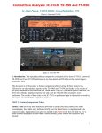
1
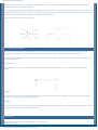
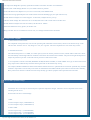
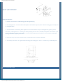
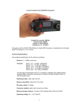
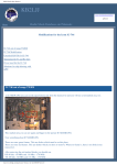
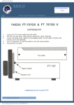
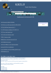
KB2LJJ Radio Mods Database and Manuals
TS-180S Mods
Note:
All the changes are at the owners option and may not be performed in warranty.
www.r6-ru4montesecchieta.it
IZ5CCV
Add 30-meter Transmit to Kenwood TS-180S Transceiver
The WARC band kit for the TS-180S is a pretty rare item these days, but I figured it should be easy to add 30m CW transmit capability to
the non-WARC stock rig, as it already receives the 10 MHz band using the normal receiver stages. The 10 MHz band is marked JJY/
WWV on the band switch.
The schematics revealed that the 30-meter part of the WARC band option adds an additional low-pass filter to the LPF board, and a band
pass "AUX 3" filter to the Coil pack board. I found you could substitute a 10.7 MHz FM transistor radio IF transformer (I used a Mouser
42IF122 for the band pass filter. For the low-pass filter I added two wire jumpers on the two rear-most sections of the band switch (at the
LPF board) so that the 7 MHz and 10 MHz lugs were connected together. This puts the 7 MHz low-pass filter section is also in-line for
the 10 MHz band.
The only tune-up necessary was to set the rig to 10.120 MHz or so and peak the new IF transformer. I achieved about 60 watts output and
confirmed the signal was clean by feeding a sample of the output into my spectrum analyzer. The spurious outputs were down below the
original specs of the rig, so I called it "good" and made some contacts on 30-meter CW.
Steve Johnston WD8DAS
DFC
For complaints of either induced power supply hum, or intermittent frequency stability while using the DFC, perform the following
changes to the VCO unit X50-1550-00:
1. Install a 330 Kohm resistor between Q11 G1 & the 8V line.
Connect from L7 at C12 to Q11 G1, at R35.
2. Replace L12 68uH with new part L40-6831-21.
3. Replace L13 150 µH with new part L40-1541-27.
4. Install magnetic shield as illustrated. Use the two existing screws, plus double faced tape to prevent vibration.
No adjustments are necessary.
Note: On page 37 of the Service Manual, the VCO Board view shows reversed callouts for Q11 & Q15. D & S, and G1 & G2 are
transposed.
http://www.kb2ljj.com/data/kenwood/TS-180S.htm (1 di 9)01/09/2009 0.06.41
KB2LJJ Radio Mods Database and Manuals
DFC Instability
TS-180S operators may report intermittent DFC instability, especially at 10 KHz even points. This may be characterized in some cases
as PM'ing.
On the VCO unit X50-1550-00, install a 330 Kohm resistor between Q11 G1, and the 8V line. Connect from L7 at C12 to Q11 G1. at
R35.
No adjustments are necessary.
Note: On page 37 of the Service Manual, the Board view of the VCO unit contains reversed callouts for Q11 & Q15 FET's, D & S, and
G1 & G2 are transposed.
DFC hum with PS-30
http://www.kb2ljj.com/data/kenwood/TS-180S.htm (2 di 9)01/09/2009 0.06.41
KB2LJJ Radio Mods Database and Manuals
Some TS-180S users may report erratic DFC, and audio hum. You will find they have placed the PS-30 to the left of the transceiver.
Hum is induced from the PS-30 into the DFC.
We are awaiting modification and production changes. Mean while, please be award of this problem. Temporarily moving the PS-30 to
the right hand side of the transceiver will cure the problem. Spacing the two units with the SP-180, or just separating at least two inches
will also cure the hum. When full information is available, we will follow up.
Please advise your Service and Sales personal.
Phone patch terminal addition
Kenwood recommends the PC-1 Phone Patch for all of our radios. Most other phone patches will work satisfactorily without any
modification to the radio, requiring only an external speaker connection, and that the Mic line be run through the patch.
For those operators who desire a Patch input similar to the TS-520S or TS-820S, an input connection and terminal must be added at the
Mic input preamp circuit.
Fixed Divider
Use a 100Kohm in series, with a 10Kohm to ground on the input side of the 100Kohm resistor. Use shielded line, and connect as
follows:
TS-120S
On the IF Gen unit X49-1110-01 install the fixed divider at the junction of R43 10K, C42 100pF, & C43 1uF (input of Q18). Add an
RCA jack, or use remote pins 7 and ground for input.
TS-180S
On the IF Gen unit X48-1240-00 install the fixed divider at the junction of R167 10K, C128 .001uF, & C129 1uF (input of Q32). Add an
RCA jack, or use remote pins 7 and ground for input.
Trouble Sheet
ALC deflection low Replace D21 on IF unit from 7.1 to 9.0V zener.
Readjust all ALC pots.
http://www.kb2ljj.com/data/kenwood/TS-180S.htm (3 di 9)01/09/2009 0.06.41
KB2LJJ Radio Mods Database and Manuals
IF #2 Output low Bridge R77 position, replace R78 with R77 470 ohms. See TKC service Bulletin.
RX Noise (OSC CAR leakage) Shorten L31, L33 leads as much as possible.
Increase NB effectiveness Replace L31, L33 for 33 uh to 27uh, with SHORT leads.
RX noise from strong signals Replace L30 10uh on the IF with self shielding type (new part L40-1035-21).
TX audio distortion Adjust T15 on the IF approx 1/2 turn back, readjust all ALC pots up.
10 M PLL unlock change: R77 from 6.8 K to 4.7 K ohm, R94 from 8.2 K to 6.8 K ohm on the PLL unit.
TX audio distortion Adjust 10 W bias for 150mA, 100 W bias for 100mA.
Unlocked all bands Check L2, (Q2 B+) in the PLL unit.
FM'ing with DFC See service bulletin of 9/10 for L12, L13 change and add resistor and shield.
Use with a Linear Amplifier
1. 1- Fast Protection with a Linear:
For complaints of fast protection, such as when operating CW semibreak-in with a linear, check C73 at the base of Q1 on the
LPF unit X51-1180-00. If it is a 1uf, change to 3.3 uf, 25v or greater. This will compensate for slow linear relay closure.
2. 2- Premature Protection
The radio should protect at 3:1 SWR, or at 24W open (no) load. To test the protection circuit, load the radio at 24W into a know
500 ohm dummy load through a Bird 43 wattmeter. Disconnect the load from the wattmeter. The protection light should just lite.
Adjust the protection pot VR1 on the LPF unit for protectio at 24W with no load.
3. 3- For complaints of VOX CYCLING, MEMORY JUMP, READOUT JUMP, or TONE "BEEP" at key up or down with a linear
amp, suspect linear induced relay transients entering the radio via the ASSY relay wiring.
For example, DRAKE L4B linears before Serial Number 5500 do not have a quench diode across the DC operated relay. Install a
1N4005 or equivalent across the relay in the linear to eliminate the back EMF induced by the linear into the TS-180S. Similarly,
Henry linears also don't have a diode across the relay and may give these symptoms when operated with a TS-180S.
Low Pass Filter Optional Changes
1. Transmitter ALC levels may be increased by these optional component changes. Check for correct component values when
installing the CK-18 kit.
On the LPF Unit X51-1180-00 change:
7 MHz
C14 from 470pf to 390pf (CM93D2H391J)
C17 from 470pf to 390pf (CM93D2H391J)
18 and 21 MHz
C25 from 27pf to 39pf (CC45CH2H390J)
C26 from 82pf to 68pf (CC45CH2H680J)
C28 from 82pf to 120pf (CC45CH2H121J)
http://www.kb2ljj.com/data/kenwood/TS-180S.htm (4 di 9)01/09/2009 0.06.41
KB2LJJ Radio Mods Database and Manuals
C29 from 27pf to 39pf (CC45CH2H390J)
24.5 and 28 MHz
C30 from 18pf to 39pf (CC45CH2H390J)
C34 from 18pf to 39pf (CC45CH2H390J)
All capacitors should be 500V silver mica or disc ceramic, 5%.
ALC Adjustment. After these component changes, perform ALC alignments 4-4, 4-5, and 4-6 as listed in the Service Manual. Be
sure to adjust to spec.; incorrect meter zero (4-4), output exceeding 95W (4-5), or failure to peak T1 (RF unit) and L15 (IF unit)
(4-6) will result in low or no ALC and possible future damage to the power amplifier.
2. Fast protection with a linear amplifier. While working in the LPF unit, check the value of C73 (base of Q1). If it is 1uf, change to
a 3.3 uf @ 25v dc tantalum (CS15E1E3R3M). This will compensate fro slow linear amplifier relay closure.
BS-8 Alignment
The SM-220/BS-8 scope combination are fully compatible with the TS-180S transceiver. However, as the TS-180S does not have a
25kHz calibrator, BS-8 alignment will not be in accordance with the SM-220 Operating Manual.
Procedure:
Install the BS-8 in accordance with the SM-220 Manual, however, leave the scope covers off until step 1 is completed (If input
alignment.) See note 1.2.
Perform steps 8.4.1, 8.4.2. steps 8.4.3, 8.4.4 do not apply to the TS-180S. After step 8.4.2. continue:
1. With the Marker ON, turn the transceiver ON, and in the USB mode, any band, you should hear the scope Marker directly
injected into the IF.
Peak T201, the BS-8 input IF transformer, for maximum signal into the TS-180S. This transformer is not shown in Fig. 8-2, but
is the only other adjustment on the BS-8, and is located below the three identified sccess openings. If you cannot hear the Scope
Marker in the TS-180S, turn the marker off and tune a local station on the 1.5 MHz band. Peak the drive control, and then peak
T1 in the BS-8 for maximum amplitude at scope center and equal roll-off at the display edges. See note 1 Page 2.
2. Turn of TS-180S, 1.5 MHz band, and tune to the local AM broadcast station nearest 1.6 MHz.
3. Enter this frequency in the M1 Memory. Depress the DSP/Diff pushbutton for a differential display.
4. Tune up and down approximately 100KHz, observing the scope display. Note the verticale displacement of the original
frequency to the left and right. If equal, or linear displacement is obseved, stop.
5. If the display does not shift equally when tuned up or down frequency, adjust VR202 for linearity of scan width. Then reset to
the center frequency (by the cope Marker or retuning the transceiver). Reset TC201 if necessary. Repeat two or three times for
correct scope center frequency, and linear display.
6. Turn the TS-180S off, and the scope marker on. Switching between 100khz and 20khz scan widths, the marker should appear at
scoep center, and should not shift. Repeat step 5 if there is a shift.
Notes:
1. A Bs-8 previously aligned to a TS-820 or TS-820S need only have step 1., input alignment, performed.
2. Preset TC201, VR201, VR202 at their center. When alignment is complete, these adjustments should not be at their extreme
limits. This will result in unstable Pan display operation. Rather, they should be somewhat within their center range.
Please make these changes in your service manual.
CW Delay During VOX Memory Operation
http://www.kb2ljj.com/data/kenwood/TS-180S.htm (5 di 9)01/09/2009 0.06.41
KB2LJJ Radio Mods Database and Manuals
Some operators may report missing the first dit during CW VOX operation on the memories. This will occur only in early units, and may
be improved by changing one capacitor in the DFC.
On the DFC VCO unit X50-1550-00, check C3 at the base of Q3. If C3 is a 22uF electrolytic, change to a .01uf disc.
No adjustments are necessary.
Low 40M ALC
Please annotate your service manual.
Some operators may experience intermittent reduction or loss of ALC, especially after several minutes transmit time.
On the LPF unit X51-1180-00, change C14, C17 from 470 pf to 390 pF. Check ALC level and adjust if necessary, per section 406 ALC
meter adjustmet, TS-180S service Manual.
New part: CM93D2H390J 390pF +/- 5% 500v mica or ceramic
Please annotate your Service Manual.
VFO Stability
VFO drift characteristics may be improved by changing a capacitor value and location in the VFO.
1. 1- Begin by calibrating the analog dial to the Digital Display at 14.000.0 MHz. DO NOT disturb this calibration while working
on the VFO.
2. 2- Turn off the main power and remove the VFO unit by two 3mm hex head bolts.
3. 3- Withdraw out the front panel and unplug the leads.
4. 4- Remove C17 from the PCB. This may be cut flush to the board.
5. 5- Install the 18 pF yellow cap across the tank coil terminals. Position the cap near the coil.
6. 6- To reassemble, performs steps 3, 2. Snug all VFO case screws. A later complaint of frequency jump would indicate a loose
VFO shell.
7. 7- Turn on the radio and check analog dial calibration against the Digital Display. Adjust VC1 (center of the Seal Tape) only if
the zero-point has moved.
8. 8-VFO linearity final check: The Digital readout and analog dial should agree to within +/- 2 kHz at every 100 kHz dial point.
http://www.kb2ljj.com/data/kenwood/TS-180S.htm (6 di 9)01/09/2009 0.06.41
KB2LJJ Radio Mods Database and Manuals
New Part: 18 pF CC45RC1H180J
Old Part: 18 pF CC45PG1H180J
Analog Dial Calibration
1. 1- Calibrate the main knob to 50 kHz analog against the digital display.
2. 2- Note the digital error. If it is more than 2 kHz adjust the VFO trimmer cap VC1 (center under the sealing tape) to exactly 50.0
on the digital readout.
3. 3- Turn the main knob to 450 analog. If the digital error is less than 2 kHz it is in spec. If the digital error greater, proceed:
For instance, if the digital error is 14.454.0 (plus 4 kHz), multiply the error times 4 (16 kHz) and adjust the VFO trimmer cap to
the desired frequency (14.450.0) LESS the error, or 14.434.0. Next, adjust the VFO inductor L1 (front under the sealing tape)
back up to the desired frequency of 14.450.0.
4. 4- If the error in step 3 was in the minus direction, reverse the direction of correction adjustment.
5. 5- VFO linearity final check: The digital readout and analog dial should agree to within +/- 2 kHz at every 100 kHz dial point.
Increase of RX Audio Output
http://www.kb2ljj.com/data/kenwood/TS-180S.htm (7 di 9)01/09/2009 0.06.41
KB2LJJ Radio Mods Database and Manuals
RX audio output from the TS-180S may be increased a total of 4.7 dB. This is an optional change which you can make at the owners
request.
On the IF unit X48-1240-00 change components:
R206 2.2K change to 1 K ohn
R207 2.2K change to 4.7 K ohm
On the AF Gain Control, between pin 1 and 3;
C4 .047uF change to .027uF mylar
Please notate your service manual.
IF output #2 Level Change for SM-220
TS-180S owners who desire to operate an SM-220 for IF output display will require a wiring change to the IF unit X48-1240-00. No
additional parts and no adjustments are required.
Remove R77, 470 ohm, and replace with wire jumper. Remove R78, 56 ohm, and replace with old R77. The 56 ohm resistor is not used.
With AGC on, gain should be adequate for about a 3/4 screen display.
http://www.kb2ljj.com/data/kenwood/TS-180S.htm (8 di 9)01/09/2009 0.06.41
KB2LJJ Radio Mods Database and Manuals
ATTENTION
The KB2LJJ takes no responsibility for any damage during the modification or for any wrong information made on this modification.
http://www.kb2ljj.com/data/kenwood/TS-180S.htm (9 di 9)01/09/2009 0.06.41