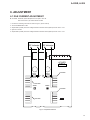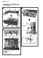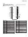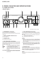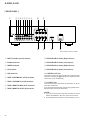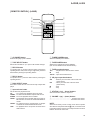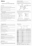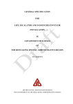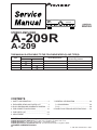
1
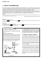
STEREO AMPLIFIER
POWER
z¿<?/B Direct Energy MOS
VOLUME
Î
CD
— OFF
TUNER
PHONO
LINE
TAPE 1
/CD-R/MD
TAPE 2
MONITOR
_ ON
BASS
A SPEAKERS B
TREBLE
BALANCE
PHONES
LOUDNESS
–
+
–
+
INPUT SELECTOR
DIRECT
MIN
MAX
ORDER NO.
TAPE 2
MONITOR
L
R
RRV2283
STEREO AMPLIFIER
A-209R
A-209
THIS MANUAL IS APPLICABLE TO THE FOLLOWING MODEL(S) AND TYPE(S).
Type
Model
A-209R
A-209
MYXJ
–
MVXJ
–
Power Requirement
AC220-230V
The voltage can be converted by
the following method.
–––––
AC220-230V
–––––
MLXJ
–
AC220-230V
–––––
SBDXJ
–
AC110V/120-127V/220V/240V
With the voltage selector
CONTENTS
1. SAFETY INFORMATION ...................................... 2
2. EXPLODED VIEWS AND PARTS LIST ............... 3
3. BLOCK DIAGRAM AND SCHEMATIC DIAGRAM ..... 6
4. PCB CONNECTION DIAGRAM ......................... 16
5. PCB PARTS LIST ............................................... 24
6. ADJUSTMENT .................................................... 27
7. GENERAL INFORMATION ................................
7.1 DISASSEMBLY ............................................
7.2 IC ..................................................................
8. PANEL FACILITIES AND SPECIFICATIONS .......
28
28
29
30
PIONEER CORPORATION
4-1, Meguro 1-chome, Meguro-ku, Tokyo 153-8654, Japan
PIONEER ELECTRONICS SERVICE, INC. P.O. Box 1760, Long Beach, CA 90801-1760, U.S.A.
PIONEER EUROPE N.V. Haven 1087, Keetberglaan 1, 9120 Melsele, Belgium
PIONEER ELECTRONICS ASIACENTRE PTE. LTD. 253 Alexandra Road, #04-01, Singapore 159936
c PIONEER CORPORATION 2000
T – ZZK APR. 2000 Printed in Japan
A-209R, A-209
1. SAFETY INFORMATION
This service manual is intended for qualified service technicians ; it is not meant for the casual do-ityourselfer. Qualified technicians have the necessary test equipment and tools, and have been trained
to properly and safely repair complex products such as those covered by this manual.
Improperly performed repairs can adversely affect the safety and reliability of the product and may
void the warranty. If you are not qualified to perform the repair of this product properly and safely, you
should not risk trying to do so and refer the repair to a qualified service technician.
WARNING
This product contains lead in solder and certain electrical parts contain chemicals which are known to the state of California to cause
cancer, birth defects or other reproductive harm.
Health & Safety Code Section 25249.6 – Proposition 65
NOTICE
(FOR CANADIAN MODEL ONLY)
Fuse symbols
(fast operating fuse) and/or
be of identical designation.
(slow operating fuse) on PCB indicate that replacement parts must
REMARQUE
(POUR MODÈLE CANADIEN SEULEMENT)
Les symboles de fusible
(fusible de type rapide) et/ou
de remplacement doivent avoir la même désignation.
(fusible de type lent) sur CCI indiquent que les pièces
(FOR USA MODEL ONLY)
1. SAFETY PRECAUTIONS
The following check should be performed for the
continued protection of the customer and service
technician.
ANY MEASUREMENTS NOT WITHIN THE LIMITS
OUTLINED ABOVE ARE INDICATIVE OF A POTENTIAL
SHOCK HAZARD AND MUST BE CORRECTED BEFORE
RETURNING THE APPLIANCE TO THE CUSTOMER.
LEAKAGE CURRENT CHECK
Measure leakage current to a known earth ground (water
pipe, conduit, etc.) by connecting a leakage current tester
such as Simpson Model 229-2 or equivalent between the
earth ground and all exposed metal parts of the appliance
(input/output terminals, screwheads, metal overlays, control
shaft, etc.). Plug the AC line cord of the appliance directly
into a 120V AC 60Hz outlet and turn the AC power switch
on. Any current measured must not exceed 0.5mA.
Reading should
Leakage not be above
current 0.5mA
tester
Device
under
test
Test all
exposed metal
surfaces
Also test with
plug reversed
(Using AC adapter
plug as required)
AC Leakage Test
2
Earth
ground
2. PRODUCT SAFETY NOTICE
Many electrical and mechanical parts in the appliance
have special safety related characteristics. These are
often not evident from visual inspection nor the protection
afforded by them necessarily can be obtained by using
replacement components rated for voltage, wattage, etc.
Replacement parts which have these special safety
characteristics are identified in this Service Manual.
Electrical components having such features are identified
by marking with a on the schematics and on the parts list
in this Service Manual.
The use of a substitute replacement component which does
not have the same safety characteristics as the PIONEER
recommended replacement one, shown in the parts list in
this Service Manual, may create shock, fire, or other hazards.
Product Safety is continuously under review and new
instructions are issued from time to time. For the latest
information, always consult the current PIONEER Service
Manual. A subscription to, or additional copies of, PIONEER
Service Manual may be obtained at a nominal charge from
PIONEER.
A-209R, A-209
2. EXPLODED VIEWS AND PARTS LIST
NOTES:
• Parts marked by "NSP" are generally unavailable because they are not in our Master Spare Parts List.
• The mark found on some component parts indicates the importance of the safety factor of the part.
Therefore, when replacing, be sure to use parts of identical designation.
• Screws adjacent to mark on the product are used for disassembly.
2.1 PACKING
(1) PACKING PARTS LIST
MVXJ type Only
16 (SBDXJ
type Only)
20
17
19
Except
MVXJ type
Mark No.
1
18
2
12
5 15
(SBDXJ type
Only)
6
7 1 (MYXJ and
MVXJ types
Only)
2 (MYXJ type
Only)
13
8
3 (MYXJ type
Only)
4 (MYXJ and
MVXJ types
Only)
14 (MLXJ and
SBDXJ types
Only)
FR
ON
T
10
3
NSP
NSP
NSP
NSP
4
5
6
7
8
Description
Part No.
Operating Instructions
See Contrast table(2)
(English)
Operating Instructions
See Contrast table(2)
(German)
Operating Instructions
See Contrast table(2)
(French/Italian/Dutch/Swedish/Spanish/Portugese)
Warranty Card
Remote Control Unit (CU-A019)
Battery Cover
Dry Cell Battery (AA/R6P)
Side Pad L
See Contrast table(2)
See Contrast table(2)
See Contrast table(2)
See Contrast table(2)
AHA7205
9
10
11
12
13
Side Pad R
Sub Pad
Packing Case
Literature Bag
Packing Sheet
AHA7206
AHA7218
See Contrast table(2)
AHG1180
AHG7015
14
See Contrast table(2)
15
16
17
Operating Instructions
(English/Spanish/Chinese)
Caution Label 220V
AC Plug Adapter
Air Cap
See Contrast table(2)
See Contrast table(2)
See Contrast table(2)
18
19
20
Power Cord
Power Cord with Fuse
Fuse (T5A)
See Contrast table(2)
See Contrast table(2)
See Contrast table(2)
9
11
(2) CONTRAST TABLE
A-209R/MYXJ, MVXJ, A-209/MLXJ and SBDXJ are constructed the same except for the following :
Mark
No.
1
2
3
A-209R
/MYXJ
Part No.
A-209R
A-209
/MVXJ
/MLXJ
A-209
/SBDXJ
Operating Instructions (English)
Operating Instructions (German)
Operating Instructions (French/Italian/
Dutch/Swedish/Spanish/Portuguese)
Warranty Card
ARB7236
ARC7322
ARC7323
ARB7236
Not used
Not used
Not used
Not used
Not used
Not used
Not used
Not used
ARY7022
ARY7022
Not used
Not used
Symbol and Description
NSP
4
NSP
5
6
7
11
14
Remote Control Unit (CU-A019)
Battery Cover
Dry Cell Battery (AA/R6P)
Packing Case
Operating Instructions
(English/Spanish/Chinese)
AXD7193
AZN2249
VEM-013
AHD7869
Not used
AXD7193
AZN2249
VEM-013
AHD7869
Not used
Not used
Not used
Not used
AHD7870
ARE7269
Not used
Not used
Not used
AHD7891
ARE7269
NSP
15
16
17
18
19
Caution Label 220V
AC Plug Adapter
Air Cap
Power Cord
Power Cord with Fuse
Not used
Not used
Not used
ADG1154
Not used
Not used
Not used
AHG1087
Not used
ADG1156
Not used
Not used
Not used
ADG1154
Not used
ARR1003
VKX1007
Not used
ADG1154
Not used
20
Fuse (T5A)
Not used
AEK1046
Not used
Not used
Remarks
3
A-209R, A-209
2.2 EXTERIOR
39
26
36
39
39
26
39
39
SBDXJ
43
Type Only
39
15
15
8
4
6
3
35
MYXJ,
MVXJ
Types Only
15
1
34
15
37
39
5
7
28 or 44
25 MYXJ,
MVXJ
Types Only
2
18
9
41
17
13
38
SBDXJ
Type Only
42
16
11
30
39
41
27
39
39
27
29
47
39
19
40
23
19
23
31
12
33
22
31
23
32
39
46
14
39 17
46
48
46
45 MLXJ,
SBDXJ
21
49
14
21
4
39
14
MYXJ,
39 MVXJ
A-209R, A-209
(1) EXTERIOR PARTS LIST
Mark No.
NSP
NSP
NSP
NSP
NSP
Description
Part No.
Mark No.
Description
Part No.
1
2
3
4
5
FRONT L Assy
FRONT R Assy
OPT Assy
AC PRIMARY Assy
HEADPHONE Assy
See Contrast table(2)
See Contrast table(2)
See Contrast table(2)
See Contrast table(2)
AWX7114
26
27
28
29
30
Screw (3 × 8)
LED Lens
IR Filter
LED Lens A
Name Plate
PBA1096
AAK2459
See Contrast table(2)
AAK7537
PAM1776
6
7
8
9
See Contrast table(2)
See Contrast table(2)
See Contrast table(2)
ADD7032
31
32
33
34
35
Rotary Knob A
Rotary Knob B
Volume Knob
Speaker Button
Power Joint
AAB7148
AAB7149
AAB7150
AAD7435
AAD7439
10
VOLUME Assy
AF Assy
Fuse (FU1)
Flexible Cable (19P)
(AF CN202-FRONT R CN601)
•••••
11
12
13
14
15
Power Transformer (T1)
Chassis
Rear Panel
Insulator
Screw (3 × 8)
See Contrast table(2)
ANA7064
See Contrast table(2)
See Contrast table(2)
ABA1018
36
37
38
39
40
Bonnet Case
Panel Base
Front Panel
Screw
Screw
ANE7183
AMB7489
See Contrast table(2)
BBZ30P080FZK
BCZ30P060FCC
16
17
18
19
20
Screw (3 × 8)
Screw (4 × 10)
Nut
PCB Support
•••••
ABA1027
ABA7047
ABN-065
AEC7006
41
42
43
44
45
Nut
Voltage Selector (S2)
Fuse (FU2, FU3 : 1.25A)
PVC Cover
Foot
NK90FUC
See Contrast table(2)
See Contrast table(2)
See Contrast table(2)
See Contrast table(2)
21
22
23
24
25
PCB Holder
Cord Clamp F
PCB Mold
•••••
Shield Plate
AEC7057
AEC7134
AMR2533
46
47
48
49
Spacer
Transformer Plate
Sub Frame
Screw
ABF7004
ANG7312
ANG7313
IBZ30P120FCC
NSP
See Contrast table(2)
(2) CONTRAST TABLE
A-209R/MYXJ, MVXJ, A-209/MLXJ and SBDXJ are constructed the same except for the following :
Mark
NSP
No.
Symbol and Description
A-209R
/MYXJ
Part No.
A-209R
A-209
/MVXJ
/MLXJ
A-209
/SBDXJ
1
2
3
4
6
FRONT L Assy
FRONT R Assy
OPT Assy
AC PRIMARY Assy
VOLUME Assy
AWX7123
AWX7124
AWX7125
AWX7113
AWX7118
AWX7123
AWX7124
AWX7125
AWX7113
AWX7118
AWX7122
AWX7121
Not used
AWX7113
AWX7112
AWX7122
AWX7121
Not used
AWX7670
AWX7112
7
8
8
11
11
AF Assy
Fuse (FU1 : 1.25A)
Fuse (FU1 : 6.3A)
Power Transformer (AC220-230V)
Power Transformer
(AC110V/120-127V/220V/240V)
AWX7117
REK1023
Not used
ATS7190
Not used
AWX7117
REK1023
Not used
ATS7190
Not used
AWX7116
REK1023
Not used
ATS7190
Not used
AWX7116
Not used
REK1030
Not used
ATS7191
13
14
25
28
38
Rear Panel
Insulator
Shield Plate
IR Filter
Front Panel
ANC7925
PNW2766
ANK7043
AAK7532
AMB7710
ANC7925
PNW2766
ANK7043
AAK7532
AMB7710
ANC7927
AMR7198
Not used
Not used
AMB7711
ANC7928
AMR7198
Not used
Not used
AMB7711
42
43
44
45
Voltage Selector (S2)
Fuse (FU2, FU3 : 1.25A)
PVC Cover
Foot
Not used
Not used
Not used
Not used
Not used
Not used
Not used
Not used
Not used
Not used
AAK7541
REC1263
AKX-507
REK1023
AAK7541
REC1263
Remarks
5
1
2
3
4
A-209R, A-209
3. BLOCK DIAGRAM AND SCHEMATIC DIAGRAM
A
3.1 BLOCK DIAGRAM
CN101
CN102
2.8mV
/50kΩ
IC151
RIAA
3
PHONO
D
1
37dB
IC101
FUNCTION
TUNER
Q101
CD
ON/OFF
AF ASSY
27
24
26
24
Q501
Q503
LOUDNESS
19
CN203
17
200mV
/50kΩ
25
24
12
20
LINE
CN501
12
18
VOLUME
TAPE1
/CD-R
/MD
B
200mV
/1kΩ
M VR501
Q103
1, 2
CN203
1, 2
REC
200mV TAPE2
/50kΩ MONITOR
200mV
/1kΩ
CN501
Q337-Q340
UP/DOWN
REC
F
D
C
FRONT R ASSY
Q331, Q327, Q328
FROM UNUSUAL
OUTPUT DETECTION
TO FUNCTION SW
38
E
DIRECT, LOUDNESS ON/OFF
23, 24,
36, 40,
µ-COM
42
FROM FUNCTION SEL
S601
IC601
D
12, 15
32, 33
30, 31
Q501–Q514
D
Q337–Q340
D
Q303
D
Q334, Q336
FUNC MUTE ON/OFF
37
604
SR INPUT
A
VOLUME UP/DOWN
17
1
G
IC101
2, 3, 4
KEY INPUTS
S602, S603
S702–S704
D
TO PROTECTION RY
6
1
2
3
4
5
6
7
8
A-209R, A-209
A
A
D
VOLUME ASSY
AF ASSY
DIRECT ENERGY MOS
DIRECT
ON/OFF
POWER AMP
WRLC
39dB
Q505
CN501
CN203
8
Q507
7
J3
6
J551
FUNC
MUTE
6
TONE
7
AND
BALANCE
SP-B
RY403
Q303
6
401
SP-A
RY402
IC301
Q309–Q330
Q509
CN502
7
8
PROTECTION RY
RY401
1
B
UNUSUAL
OUTPUT
DETECTION
J551
B
Q331, Q327, Q328
1
H.P
JA501
HEADPHONE ASSY
E
IC751
FRONT L ASSY
VR751
VR752
F VR601
D
C
AF ASSY
+BL
TO POWER STAGE
D451
–BL
TO µ-COM
LED
+6
IC453
TO OP AMP
RY
IC451
IC452
+19
C
–15
AC PRIMARY ASSY
T1
Q451
S801 FU1
+BH
REGULATOR
TO VOLTAGE STAGE
D
–BH
Q452
D452–D455
7
5
6
7
8
1
2
3
4
A-209R, A-209
3.2 OVERALL CONNECTION DIAGRAM
A
F
B
FRONT R ASSY
AWX7124 (MYXJ, MVXJ)
AWX7121 (MLXJ, SBDXJ)
HEADPHONE ASSY
AWX7114
B
D
AF ASSY
AWX7117 (MYXJ, MVXJ)
AWX7116 (MLXJ, SBDXJ)
C
451
A
VOLUME ASSY
AWX7118 (MYXJ, MVXJ)
AWX7112 (MLXJ, SBDXJ)
D
8
1
2
3
4
5
6
7
8
A-209R, A-209
Note : When ordering service parts, be sure to refer to "EXPLODED VIEWS and PARTS LIST" or "PCB PARTS LIST".
A
E
FRONT L ASSY
AWX7123 (MYXJ, MVXJ)
AWX7122 (MLXJ, SBDXJ)
B
AC POWER CORD
C
G
ADG1154 : MYXJ, MLXJ types
AC PRIMARY ASSY
AWX7113
(MYXJ, MVXJ, MLXJ)
AWX7670
(SBDXJ)
OPT ASSY
AWX7125
(MYXJ, MVXJ)
ADG1156 : MVXJ type
ADG1154 (VKX1007) : SBDXJ type
MYXJ, MVXJ,
MLXJ types
SBDXJ type
POWER TRANSFORMER
ATS7190 : MYXJ, MVXJ, MLXJ
(VKX1007)
A-209/SBDXJ
C
S2 : AKX-507
VOLTAGE
SELECTOR
POWER TRANSFORMER
ATS7191 : SBDXJ
D
9
5
6
7
8
1
2
3
4
A-209R, A-209
3.3 VOLUME and HEADPHONE ASSYS
A
B
HEADPHONE ASSY
AWX7114
D
J551A
: AUDIO SIGNAL ROUTE
B
VOLUME ASSY
AWX7118 (MYXJ, MVXJ)
AWX7112 (MLXJ, SBDXJ)
J3
A
E
C
ACX7038
VR-501 : ACX7038 (MYXJ, MVXJ)
VR-501 : ACS7035 (MLXJ, SBDXJ)
(MYXJ, MVXJ)
D
D CN203
10
A B
1
2
3
4
1
2
3
4
A-209R, A-209
3.4 AC PRIMARY ASSY
A
• NOTE FOR FUSE REPLACEMENT
CAUTION - FOR CONTINUED PROTECTION AGAINST RISK OF FIRE.
REPLACE WITH SAME TYPE AND RATINGS ONLY.
C
AC PRIMARY ASSY
AWX7113 (MYXJ, MVXJ, MLXJ)
AWX7670 (SBDXJ)
MYXJ, MVXJ, MLXJ types
SBDXJ type
SBDXJ type
POWER
REK1023
T1.25AL250V
LIVE
S801
ASG1035
TO POWER
TRANSFORMER
TO
AC POWER
CORD
MYXJ,
MVXJ,
MLXJ types
B
NEUTRAL
REK1023
T1.25AL250V
A-209/SBDXJ
C
TO S2
VOLTAGE
SELECTOR
D
C
1
2
3
4
11
1
2
3
4
A-209R, A-209
3.5 AF ASSY
: AUDIO SIGNAL ROUTE
A
1k
D
AF ASSY
AWX7117 (MYXJ, MVXJ)
AWX7116 (MLXJ, SBDXJ)
1k
C313,C337 :
B
IDLE ADJ.
(L CH)
C314,C338 :
C
IDLE ADJ.
(R CH)
MYXJ, MVXJ ONLY
D
MYXJ, MVXJ ONLY
12
A CN501
D
1
2
3
4
5
6
7
8
A-209R, A-209
A
CAUTION : FOR CONTINUED PROTECTION AGAINST
RISK OF FIRE. REPLACE ONLY WITH
SAME TYPE NO. 491001 MFD, BY
LITTELFUSE INK. FOR IC454 (AEK7009).
ACH7080
(6800/42)
C452
ACH7081
(6800/42)
TO POWER
TRANSFORMER
IRF530(S)
C451
R361–R366:
IRF9530(S)
B
IRF530(S)
C
IRF9530(S)
C321–C324:
Q333–Q336:
D
B J551
F
5
D
CN601
6
7
8
13
1
2
3
4
A-209R, A-209
3.6 FRON L, FRONT R and OPT ASSYS
G
A
OPT ASSY
AWX7125
E
FRONT L ASSY
AWX7123 (MYXJ, MVXJ)
AWX7122 (MLXJ, SBDXJ)
(MYXJ, MVXJ)
VSG1009
VSG1009
MYXJ, MVXJ ONLY
A
CN502
VSG1009
B
D
CN202
C
D
14
FRONT L ASSY
S702 : LOUDNESS
S703 : SPEAKER A
S704 : SPEAKER B
E F G
1
2
3
4
5
6
7
8
A-209R, A-209
A
F
FRONT R ASSY
AWX7124 (MYXJ, MVXJ)
AWX7121 (MLXJ, SBDXJ)
MYXJ, MVXJ ONLY
MYXJ, MVXJ ONLY
B
VSG1009
VSG1009
INPUT
SELECTOR
C
MYXJ, MVXJ ONLY
FRONT R ASSY
S601 : INPUT SELECTOR
CD
TUNER
PHONE
LINE
TAPE1/CD-R/MD
S602 : DIRECT
S603 : TAPE2 MONITOR
D
F
5
6
7
8
15
1
2
3
4
A-209R, A-209
4. PCB CONNECTION DIAGRAM
4.1 VOLUME ASSY
NOTE FOR PCB DIAGRAMS :
A
1. Part numbers in PCB diagrams match those in the schematic
diagrams.
2. A comparison between the main parts of PCB and schematic
diagrams is shown below.
Symbol In PCB
Diagrams
Symbol In Schematic
Diagrams
B C E B C E
Part Name
3. The parts mounted on this PCB include all necessary parts for
several destinations.
For further information for respective destinations, be sure to
check with the schematic diagram.
4. View point of PCB diagrams.
Connector
Capacitor
Transistor
B C E
B
C
E B
C
SIDE A
E
Transistor
with resistor
B C E
D
G S D
G S
Field effect
transistor
D G S
P.C.Board
SIDE B
A VOLUME ASSY
Resistor array
B
Chip Part
3-terminal
regulator
E J3
Q513,Q514
SIDE A
VR501
C
(ANP7232-A)
D CN203
A VOLUME ASSY
Q509,Q510
Q507,Q508
Q505,Q506
Q511
SIDE B
Q503,Q502
D
Q501,Q504
16
A
1
(ANP7232-A)
2
3
4
1
2
3
4
A-209R, A-209
4.2 HEADPHONE and AC PRIMARY ASSYS
A
B HEADPHONE ASSY
SIDE A
(ANP7232-A)
B HEADPHONE ASSY
D J551A SIDE B
(ANP7232-A)
C AC PRIMARY ASSY
POWER
TRANSFORMER
B
VOLTAGE
SELECTOR
(SBDXJ Type)
SIDE A
AC POWER
CORD
(ANP7232-A)
C
C AC PRIMARY ASSY
SIDE B
D
(ANP7232-A)
1
2
3
B C
4
17
1
2
3
4
2
3
4
A-209R, A-209
4.3 AF ASSY
A
D AF ASSY
B
C
D
POWER
TRANSFORMER
18
D
1
5
6
7
8
A-209R, A-209
SIDE A
A
Q153
Q341
IC101
IC451-IC453
F CN601
B
Q333-Q336
Q324,Q326
VR302
Q452
C
IC301
A CN501
Q451
VR301
Q323,Q325
IC454
D
B J551
(ANP7232-A)
5
6
7
D
8
19
1
2
3
4
2
3
4
A-209R, A-209
D AF ASSY
A
B
C
D
20
D
1
5
6
7
8
A-209R, A-209
SIDE B
Q151
IC151
Q152
Q338,Q337
A
Q340,Q339
Q102
Q101
Q104
B
Q103
Q332
Q328,Q327
Q318,Q330
Q322,Q320
Q316,Q314
C
Q312,Q310
Q304,Q303
Q311,Q309
Q315,Q313
Q321,Q319
Q317,Q329
Q331,Q343
D
(ANP7232-A)
5
6
7
D
8
21
1
2
3
4
A-209R, A-209
4.4 FRONT L ASSY
A
E FRONT L ASSY
G J603A
A CN502 F J602
VR751
VR752
Q707
Q708
(ANP7231-A)
SIDE A
B
E FRONT L ASSY
IC751,Q701
Q703,Q702
Q705,Q704
(ANP7231-A)
C
SIDE B
D
22
E
1
2
3
4
1
2
3
4
A-209R, A-209
4.5 FRONT R and OPT ASSYS
F FRONT R ASSY
A
IC601
VR601
B
E J602A
F
SIDE A
D CN202
(ANP7231-A)
FRONT R ASSY
Q608-Q613
C
Q614-Q616
Q601-Q606
(ANP7231-A)
SIDE B
G OPT ASSY
G OPT ASSY
D
E J603
(ANP7231-A)
(ANP7231-A)
SIDE A
1
SIDE B
2
3
F G
4
23
A-209R, A-209
Mark No.
Description
Part No.
Mark No.
Description
Part No.
5. PCB PARTS LIST
• Parts marked by "NSP" are generally unavailable because they are not in our Master Spare Parts List.
• The mark found on some component parts indicates the importance of the safety factor of the part.
Therefore, when replacing, be sure to use parts of identical designation.
• When ordering resistors, first convert resistance values into code form as shown in the following examples.
NOTES:
Ex.1 When there are 2 effective digits (any digit apart from 0), such as 560 ohm and 47k ohm (tolerance is shown by J=5%,
and K=10%).
561 ........................................................ RD1/4PU 5 6 1 J
560 Ω
→
56 × 101 →
473 ........................................................ RD1/4PU 4 7 3 J
47k Ω
→
47 × 103 →
0.5 Ω
→
R50 ..................................................................................... RN2H R 5 0 K
1Ω
→
1R0 ..................................................................................... RS1P 1 R 0 K
Ex.2 When there are 3 effective digits (such as in high precision metal film resistors).
5621 ...................................................... RN1/4PC 5 6 2 1 F
5.62k Ω →
562 × 101 →
LIST OF WHOLE PCB ASSEMBLIES
Part No.
Mark
A-209R
/MYXJ
A-209R
/MVXJ
A-209
/MLXJ
A-209
/SBDXJ
AF COMPLEX ASSY
VOLUME ASSY
HEADPHONE ASSY
AC PRIMARY ASSY
AF ASSY
AWM7357
AWX7118
AWX7114
AWX7113
AWX7117
AWM7357
AWX7118
AWX7114
AWX7113
AWX7117
AWM7355
AWX7112
AWX7114
AWX7113
AWX7116
AWM7511
AWX7112
AWX7114
AWX7670
AWX7116
NSP
CONTROL ASSY
FRONT L ASSY
FRONT R ASSY
OPT ASSY
AWG7013
AWX7123
AWX7124
AWX7125
AWG7013
AWX7123
AWX7124
AWX7125
AWG7012
AWX7122
AWX7121
Not used
AWG7012
AWX7122
AWX7121
Not used
Mark No.
Description
NSP
NSP
Symbol and Description
Part No.
Mark No.
A VOLUME ASSY
CN501 16P SOCKET
CN502 CONNECTOR 7P
PCB BINDER
AWX7118 and AWX7112 are constructed the same except
for the following :
Symbol and Description
C511
VR501
Part No.
AWX7118
AWX7112
CKSQYF473Z50 Not used
ACX7038
ACS7035
Remarks
B HEADPHONE ASSY
CAPACITORS
C501,C502
C513,C514
C516
C503,C504
C515
CCSQCH271J50
CEAT100M50
CEAT330M25
CFTYA473J50
CKCYF103Z50
C511
CKSQYF473Z50
3P CABLE HOLDER
J552
CORD WITH PLUG
JA501 HEADPHONE JACK
J551
JUMPER WIRE
RS1/10S100J
ACX7038
RS1/10S
J
51063-0305
DE005WE0
RKN1002
D15A03-150-2651
C AC PRIMARY ASSY
(1) CONTRAST TABLE
AWX7113 and AWX7670 are constructed the same except
for the following :
Mark
NSP
RESISTORS
Symbol and Description
H3-H6 FUSE CLIP
J806
Part No.
AWX7113
Not used
Not used
AWX7670
AKR7001
DB616EB0
(2) PARTS LIST FOR AWX7113
SWITCH
S801
24
CKSQYB392K50
OTHERS
2SK246
2SK303
DTC124EK
1SS352
1SS355
CAPACITORS
R530
VR501
Other Resistors
KP200TA16L
KPE7
VEF1040
C551,C552
(2) PARTS LIST FOR AWX7118
SEMICONDUCTORS
Q513,Q514
Q501-Q510
Q511
D505,D506,D509,D510
D501-D504,D507,D508
Part No.
OTHERS
(1) CONTRAST TABLE
Mark
Description
Remarks
ASG1035
Remarks
A-209R, A-209
Mark No.
Description
Part No.
Mark No.
ACG7020
AKP7005
AKR7001
D462
UDZS5.6B
OTHERS
CN801 AC INLET
H1,H2 FUSE CLIP
Part No.
S5566G(TPB2)
UDZ15B
UDZ36B
UDZ4.7B
UDZS5.1B
CAPACITORS
C801,C802 (0.01µF/AC250V)
Description
D461
D311,D312
D457,D458
D456
D341
RELAYS
D
RY401-RY403
AF ASSY
(1) CONTRAST TABLE
CAPACITORS
AWX7117 and AWX7116 are constructed the same except
for the following :
Mark
Part No.
Symbol and Description
AWX7117
2SA1162
2SC2712
2SC5174P
UDZS5.1B
Q337, Q338
Q339, Q340
Q341
D341
C334
C335, C336
C472
R385–R388
R389, R390
R391, R392
ASR7014
CEANP100M16
CEAT100M50
AWX7116
Not used
Not used
Not used
Not used
Not used
RS1/10S473J
RS1/10S471J
RS1/10S102J
Not used
Not used
Not used
Not used
Not used
R393
RS1/10S153J
R460
RS1/10S2R2J
JA401REMOTE CONTROL JACK RKN1004
Not used
Not used
Not used
CKSQYF473Z50
Remarks
(2) PARTS LIST FOR AWX7117
SEMICONDUCTORS
IC454 (1A)
IC453
IC451
IC452
IC101
AEK7009
BA178M06T
BA178M15T
NJM79M15FA
TC9163AN
IC301
IC151
Q311,Q312,Q329,Q330
Q337,Q338
Q313,Q314,Q321,Q322
UPC4570C
UPC4570G2
2SA1162
2SA1162
2SA1255
Q452
Q309,Q310,Q327,Q328
Q339,Q340
Q315,Q316,Q319,Q320
Q303,Q304
2SA1837
2SC2712
2SC2712
2SC3138
2SC3326
Q451
Q341
Q101-Q104
Q151
Q152
2SC4793
2SC5174P
2SK303
DTA124EK
DTC124EK
Q153
Q331,Q332,Q343
Q333-Q336
Q317,Q318
Q323,Q324
DTC124ES
DTC143EK
DTC143ES
IMX1
IRF530(S)
Q325,Q326
D101-D104,D151,D301-D310
D401-D404
D451
D452-D455,D459,D460
IRF9530(S)
1SS355
1SS355
D5SBA20
S5566G(TPB2)
C451 (6800µF/42V)
C452 (6800µF/42V)
C313-C316,C337-C340
C153,C154
C303,C304
ACH7080
ACH7081
CCSQCH121J50
CCSQCH151J50
CCSQCH221J50
C334
C471
C172
C333
C155,C156,C167,C168
CEANP100M16
CEANP1R0M2A
CEANP1R0M50
CEANP470M10
CEAT100M50
C317-C320,C335,C336
C453-C458,C465,C466,C469
C461,C462
C467,C468
C470
CEAT100M50
CEAT100M50
CEAT101M2A
CEAT1R0M50
CEAT3R3M50
C169,C170
C459,C460,C463,C464
C157,C158
C301,C302,C305,C306
C307,C308
CEAT470M25
CEAT470M50
CEAT471M6R3
CEBA100M50
CEBA221M25
C321-C324
C173
C165,C166
C111-C113,C171,C341
C472
CFTYA224J50
CFTYA564J50
CKSQYB222K50
CKSQYF473Z50
CKSQYF473Z50
C159,C160
C161,C162
CQMA243J50
CQMBA823J50
RESISTORS
R311,R312
R301,R302
R303,R304
R143
R133,R134,R171,R172
RDR1/4VM152J
RDR1/4VM240J
RDR1/4VM561J
RS1/10S100J
RS1/10S101J
R351-R354,R452
R317,R318,R331,R332
R357-R360
R377,R378,R453
R465-R470
RS1/10S101J
RS1/10S122J
RS1/10S151J
RS1/10S153J
RS1/10S161J
R361-R366
R339-R346
R454
R460
R355,R356
RS1/10S1R5J
RS1/10S221J
RS1/10S273J
RS1/10S2R2J
RS1/10S432J
R459
R464
R379,R380
R451
R401,R402
RS1/10S470J
RS1/10S4R7J
RS1/10S682J
RS1LMF270J
RS1LMF331J
25
A-209R, A-209
Mark No.
Description
R461-R463
R403
R373-R376
VR301,VR302 (2.2kΩ)
Other Resistors
Part No.
Mark No.
RS1LMF390J
RS1LMF821J
RS1LMFR22J
VCP1123
RS1/10S
J
OTHERS
J603
J3
OTHERS
E
3P CABLE HOLDER
SCREW
SCREW
CN101,CN102 8P PIN JACK
8P SPEAKER TERMINAL
51063-0305
ABA1007
ABA1052
AKB7023
AKE1011
HEAT SINK M
HEAT SINK B
CN202 FFC CONNECTOR 19P
CN203 16P PLUG
JA401 REMOTE CONTROL JACK
ANH-813
ANH1021
HLEM19S-1
KM200TA16
RKN1004
PCB BINDER
KN101,KN201,KN301,KN451
EARTH METAL FITTING
VEF1040
VNF1084
F
Mark
Symbol and Description
J603 JUMPER WIRE
1603 3P CABLE HOLDER
D15A03-100-2651
51063-0305
Remarks
Symbol and Description
AWX7121
Not used
CKSQYF103Z50 Not used
RS1/10S102J Not used
Remarks
Not used
Not used
IC601
Q609
Q610
Q611-Q613,Q615,Q616
Q601-Q606,Q608,Q614
PD5443A
2SA1162
2SC2712
DTA124EK
DTC124EK
D608-D612,D614-D621
D607
D601-D606
1SS355
SLP6118C51H
SLP9118C51H
S602,S603
S601
C602
C604
C603,C611
C607,C608
C605,C606,C610
UPC4570G2
2SC1845
2SC2712
DTC124EK
1SS355
RESISTORS
D701,D703,D705
SLP9118C51H
OTHERS
VR601 (500kΩ)
Other Resistors
X601
CERAMIC RESONATOR
(4.19MHz)
13P CABLE HOLDER
CN601 19P FFC CONNECTOR
J602
JUMPER WIRE
VSG1009
CAPACITORS
C753,C754,C761,C762
C767,C768
C751,C752,C755,C756
C763,C764
C759,C760
CCSQCH101J50
CCSQCH221J50
CEAL100M50
CEALR10M50
CEALR47M50
C757,C758
C701
CFTYA153J50
CKSQYF104Z25
RESISTORS
RS1/10S101J
ACS7028
RS1/10S
J
VSG1009
ASX7008
CAPACITORS
IC751
Q707,Q708
Q705
Q701-Q704
D704
R751,R752
VR751,VR752 (30kΩ)
Other Resistors
Part No.
AWX7124
1SS355
SWITCHES
SWITCHES
26
FRONT R ASSY
(2) PARTS LIST FOR AWX7124
SEMICONDUCTORS
(2) PARTS LIST FOR AWX7123
SEMICONDUCTORS
S702-S704
51063-0305
51063-0705
51063-1305
D15A03-100-2651
D15A07-200-2651
D614, D616, D621
C611
R623
AWX7123 and AWX7122 are constructed the same except
for the following :
Q704
Q705
D704
R708
R709
3P CABLE HOLDER
7P CABLE HOLDER
13P CABLE HOLDER
JUMPER WIRE
JUMPER WIRE
AWX7124 and AWX7121 are constructed the same except
for the following :
(1) CONTRAST TABLE
Mark
Part No.
(1) CONTRAST TABLE
FRONT L ASSY
Part No.
AWX7123
AWX7122
DTC124EK
Not used
2SC2712
Not used
1SS355
Not used
RS1/10S472J Not used
RS1/10S223J Not used
Description
G
CEAT102M6R3
CEJA2R2M50
CKSQYF103Z50
CKSQYF104Z25
CKSQYF473Z50
ACS7029
RS1/10S
J
VSS1014
51063-1305
9607S-19F
D15A13-125-2651
OPT ASSY
OTHERS
3P CABLE HOLDER
51063-0305
REMOTE RECEIVER UNIT GP1U27X
A-209R, A-209
6. ADJUSTMENT
6.1 IDLE CURRENT ADJUSTMENT
¶ CAUTION : Heatsinks’ (Q323–Q326) DC level is equal to +B or -B.
Don’t touch them or you will be electric shocked.
1.
2.
3.
4.
5.
Connect the measuring instrument as shown in Fig.6-1. (R373 or R374)
Turn the POWER switch to ON.
Adjust VR301 (VR302) so that the voltage between both sides of R373 (R374) becomes 10mV ± 1mV.
Ages for 5 minutes.
Adjust VR301 (VR302) so that the voltage between both sides of R373 (R374) becomes 11mV ± 1mV.
DC Voltmeter
DC Voltmeter
AF ASSY
SIDE A
R373
R374
R375
R376
Heat Sink
Heat Sink
VR301
VR302
Heat Sink
Heat Sink
CN202
Fig.6-1 Adjustment Method
27
A-209R, A-209
7. GENERAL INFORMATION
7.1 DISASSEMBLY
1
3
1 ×2
1
1
1 ×2
10
1
1
2
Front Panel
5
13
5
4 ×2
3
Diagnose the
AF Assy.
∗ : Be careful not to injure
the Front Panel.
5 ×5
11
2
Rear Panel
Chassis
6
6
6
8 Unhook lead wires.
Rear Panel
7
For
Service
7
×3
PCB Support
9
×3
Cutting Pliers
28
7 ×2
Chassis
12 Screw for Rear Panel
A-209R, A-209
7.2 IC
7 PD5443A (FRONT R ASSY : IC601)
¶ REMOTE CONTROL AMP MICROCOMPUTER
¶ Pin Assignment (Top view)
1 SR
• The information shown in the list is basic information and
may not correspond exactly to that shown in the schematic
diagrams.
T2 42
P52
P17/SRDY
2 STB
NC 41
P07
P16/CLK
3 CLK
LOUD 40
P06
M-CTRL 39
P05
P14/SIN
5 CD-IND
P-DET 38
P04
P13/T1
6 TU-IND
P-CTRL 37
P03
P12/T0
7 PH-IND
DIRECT 36
P02
NC 35
P01
WAKE UP 34
P00
P27/IN7
10 SPA-IND
FUNC2 33
P43
P26/IN6
11 SPB-IND
FUNC1 32
P42
P25/IN5
12 LOU-IND
V-UP 31
P41
P24/IN4
13 NC
V-DOWN 30
P40
P23/IN3
14 NC
RSEL2 29
P33/CNTR1
P22/IN2
15 DIR-IND
RSEL1 28
P32/CNTR0
P21/IN1
16 T2-IND
P20/IN0
17 F-MUTE
P53
P15/SOUT
4 DATA
P11
8 LI-IND
P10
9 T1-IND
VREF
XIN
XOUT
VSS
NC 27
P31/INT1
BACK UP 26
P30/INT0
18 VREF
RST 25
RESET
19 XIN
SPA 24
P51/XCOUT
20 XOUT
SPB 23
P50/XCIN
21 VSS
VCC 22
VCC
¶ Pin Function
No. Pin name I/O
Function
1
P53
I Remote control signal input pin.
2
O STB for TC9163N.
P17/SRDY
3
P16/CLK O CLOCK for TC9163N.
4
P15/SOUT
O DATA for TC9163N.
5
P14/SIN
O CD INDICATOR.
6
P13/T1
O TUNER INDICATOR.
7
P12/T0
O PHONO INDICATOR.
8
P11
O LINE INDICATOR.
9
P10
O TAPE1 INDICATOR.
10
P27/IN7
O SPEAKER-A INDICATOR.
11
P26/IN6
O SPEAKER-B INDICATOR.
12
P25/IN5
O LOUDNESS INDICATOR.
13
P24/IN4
O Not used.
14
P23/IN3
O Not used.
15
P22/IN2
O DIRECT INDICATOR.
16
P21/IN1
O TAPE2 INDICATOR.
17
P20/IN0
O FUNCTION switch MUTE.
18
VREF
I Pulls up to 5V.
19
XIN
I 4.19MHz .
20
XOUT
O Ceramic vibrating and connecting terminal.
21
VSS
- Digatal GND.
22
VCC
- Power supply +5V.
I SPEAKER-B KEY input.
23
P50/XCIN
No. Pin name I/O
Function
24 P51/XCOUT
I SPEAKER-A KEY input.
25
I Reset pin.
RESET
26
P30/INT0
I BACK UP detection pin. interrupt specification.
27
P31/INT1
I Not used.
28 P32/CNTR0 I REC selector input 1.
29 P33/CNTR1 I REC selector input 2. interrupt specification.
30
P40
O Volume DOWN data output.
31
P41
O Volume UP data output.
32
P42
I FUNCTION selector input 1.
33
P43
I FUNCTION selector input 2.
WAKE UP input.
I
34
P00
Key on wake up specification.
35
P01
O Not used.
DIRECT KEY input.
I
36
P02
Key on wake up specification.
37
P03
O Protection control pin.
38
P04
I Output error detection pin
39
P05
O MUTING control pin.
LOUDNESS KEY input.
I
40
P06
Key on wake up specification.
41
P07
O Not used.
I TAPE2 KEY input.
42
P52
29
A-209R, A-209
8. PANEL FACILITIES AND SPECIFICATIONS
8.1 PANEL FACILITIES
[ FRONT PANEL ]
1
2
3
STEREO AMPLIFIER
POWER
z¿<?/B Direct Energy MOS
4
VOLUME
Î
CD
— OFF
5
TUNER
PHONO
LINE
TAPE 1
/CD-R/MD
TAPE 2
MONITOR
_ ON
BASS
A SPEAKERS B
TREBLE
BALANCE
PHONES
LOUDNESS
–
+
~ = - 0
–
+
9
INPUT SELECTOR
DIRECT
MIN
L
MAX
8
TAPE 2
MONITOR
7
R
6
The illustration shows the A-209R.
1 POWER (— OFF/_ ON) switch
5 TAPE 2 MONITOR button/indicator
Press to turn power to the unit ON and OFF.
This unit cannot be turned ON and OFF using the remote
control unit.
(on the A-209R only)
Use when there is an adaptor component (graphic equalizer,
etc.) or cassette deck connected to the TAPE2 MONITOR
terminals.
On : Indicator lights when using the adaptor component or
listening to the cassette deck.
Off : Indicator goes off when not in use.
3 VOLUME control
NOTES:
2 REMOTE CONTROL SENSOR window
Use to adjust the volume level.
4 INPUT SELECTOR knob/indicators
Turn the knob clockwise or counterclockwise so that the
indicator lights for your desired input source. Turning the knob
clockwise causes the lit indicator to right. Turning counterclockwise causes it to left.
CD
: For compact disc playback with a CD player.
TUNER
: For AM or FM broadcast reception with a tuner.
PHONO
: For record playback with a turntable.
LINE
: Set to this position when listening to the program from a component connected to the LINE
terminals.
TAPE 1/CD-R/MD:For playback with a cassette deck,CD recorder
or MD recorder connected to TAPE1/CD-R/
MD terminals.
30
÷ When no connections are made to the TAPE2 MONITOR
terminals, or when they are not in use, be sure to set this
switch to the off position. (No sound will be heard if it is set
to the on position.)
÷ When the TAPE2 MONITOR indicator is on and the INPUT
SELECTOR knob is not set to TAPE1/CD-R/MD, the signals which are input through TAPE 2 MONITOR are then
output at TAPE1/CD-R/MD REC OUT.
6 BALANCE control
Should normally be left in the center position. Adjust balance
if the sound is louder from one of the speakers. If the right side
is louder, turn toward the L (left) position and if the left side is
louder, turn toward the R (right) position.
NOTE:
This control does not operate when the DIRECT button is in the
on position.
A-209R, A-209
7 DIRECT button/indicator
0 BASS tone control
Use this button when you do not wish to pass the output from
input terminal equipment through the various frequency adjusting circuits (BASS, TREBLE, BALANCE, LOUDNESS).
On : The indicator lights: The signals passing through the
input terminals are reproduced without passing through
the various frequency adjusting circuits. This results in
flat, pure sound which is a more faithful reproduction of
the input source.
Off : The indicator goes off: The signal passes through the
various frequency adjusting circuits.
Use to adjust the low-frequency tone. The center position is the
flat (normal) position. When turned to the right, low-frequency
tones are emphasized; when turned to the left, low-frequency
tones are de-emphasized.
8 LOUDNESS button/indicator
Use when listening at low volume levels.
On : The indicator lights: Boosts low and high frequencies to
give added punch to playback even at a low volume
level.
Off : The indicator goes off: Should normally be left in this
position.
NOTE:
This button does not operate when the DIRECT button is in the
on position.
9 TREBLE tone control
Use to adjust the high-frequency tone. The center position is
the flat (normal) position. When turned to the right, highfrequency tones are emphasized; when turned to the left, highfrequency tones are de-emphasized.
NOTE:
This control does not operate when the DIRECT button is in the
on position.
NOTE:
This control does not operate when the DIRECT button is in the
on position.
- SPEAKERS B (ON/OFF) button/indicator
Use this button to listen to the speaker system connected to
SPEAKERS B terminals.
ON : The indicator lights. Sound is heard from the speaker
system.
OFF : The indicator goes off. No sound is heard from the
speaker system. Set to this position when listening with
headphones.
= PHONES jack
When using headphones, insert the plug into this jack.
NOTE:
The speakers continue to output sound even when headphones are plugged into this jack.
To mute the sound from the speakers, press the SPEAKERS
button to OFF.
~ SPEAKERS A (ON/OFF) button/indicator
Use this button to listen to the speaker system connected to
SPEAKERS A terminals.
ON : The indicator lights. Sound is heard from the speaker
system.
OFF : The indicator goes off. No sound is heard from the
speaker system. Set to this position when listening with
headphones.
31
A-209R, A-209
[ REAR PANEL ]
1
23456789
0
-
SPEAKERS
B
R
SIGNAL
GND
PHONO
TUNER
CD
LINE
TAPE 1
/CD-R/MD
REC
TAPE 2 MONITOR
PLAY
REC
·
ª
PLAY
L
L
R
R
L
·
ª
AC INLET
CONTROL
OUT
IN
IN
IN
IN
OUT
IN
OUT
IN
R
=
A
L
~
!
@
The illustration shows the A-209R.
1 GND (Turntable ground) terminal
0 SPEAKERS B terminals (Right channel)
2 PHONO terminals
- SPEAKERS B terminals (Left channel)
3 TUNER terminals
= SPEAKERS A terminals (Right channel)
4 CD terminals
~ SPEAKERS A terminals (Left channel)
5 LINE terminals
! CONTROL OUT jack
6 TAPE 1/CD-R/MD REC (OUT) terminals
This jack is for output of control signals when operating other
components bearing the Î mark with the attached remote
control unit. (on the A-209R only)
7 TAPE 1/CD-R/MD PLAY (IN) terminals
8 TAPE 2 MONITOR REC (OUT) terminals
9 TAPE 2 MONITOR PLAY (IN) terminals
@ AC INLET jack
Connect power cord to here and an AC wall socket, or the AC
outlet of an audio timer.
If you are going to be away from home for a long period of time,
disconnect the unit from the wall socket.
NOTES:
÷ If you use an other power cord than provided, we cannot
assume the liabilities in what may occur as a result of it.
÷ (The provided power cord has a current capacity of 2.5 A.)
32
A-209R, A-209
[ REMOTE CONTROL ] (A-209R)
7
1
2
3
4
STANDBY/ON
CD
TUNER
TAPE
TAPE
SELECT
2
7
3
Ι
DECK
DECK
4
5
6
DISC
SELECT
ΙΙ
1
¢
–
TAPE
7
STATION
¡
3
CD
+
TUNER
CD
TUNER
PHONO
TAPE 1
TAPE 2
LINE
8
9
0
-
+
VOLUME
=
–
Î
STEREO AMPLIFIER
REMOTE CONTROL UNIT
1 CD POWER button
7 TUNER POWER button
Switches CD player power ON/OFF.
Switches TUNER power ON/OFF.
2 TAPE SELECT button
8 TAPE POWER button
Selects the cassette No. (1 to 6) for multi-cassette changer.
Switches the cassette deck power ON/OFF.
(Can not turn ON/OFF some cassette decks.)
3 DECK II button
To operate Deck II, press this button before pressing the
operating buttons. Also, when using a single deck, press this
button before pressing the operating buttons.
4 DECK I button
9 TAPE operation buttons
2, 3
: Playback in the direction of the arrows.
7
: Stop
1, ¡ : Tape fast forward/reverse.
To operate Deck I, press this button before pressing the
operating buttons.
0 CD player operation buttons
5 DISC SELECT button
¢
Press this to select discs on a multi or twin tray compact disc
player.
6 Input selector button
Use to select the playback source.
CD
: For compact disc playback with a CD player.
TUNER : For AM or FM broadcast reception with a tuner.
PHONO : For record playback with a turntable.
TAPE 1 : For playback with a cassette deck,CD recorder or
MD recorder connected to TAPE1/CD-R/MD terminals.
TAPE 2 : For playback with a cassette deck or adaptor
connected to TAPE 2 MONITOR terminals.
LINE
: For playback with a component connected to the
LINE terminal.
4
7
3
: Returns you to the start of the current track.
(Track search)
: Takes you to the start of the next track.
(Track search)
: Stop
: Play
- STATION + (up), – (down) buttons
Calls each station number in sequence.
= VOLUME + (up), – (down) buttons
+ ........................................................ Increases the volume.
– ...................................................... Decreases the volume.
NOTE:
When the accessory remote control unit is used to operate
other Pioneer components with the Î mark, it cannot be used
to operate functions which do not correspond to the functions
listed on the remote control unit.
33
A-209R, A-209
Power Supply/Miscellaneous
8.2 SPECIFICATIONS
Amplifier Section
Continuous power output
(both channels driven at 20 Hz to 20 kHz)**
[A-209R]
T.H.D. 0.1 %, 8 Ω ..................................... 35 W + 35 W*
T.H.D. 0.15 %, 4 Ω ................................... 45 W + 45 W*
DIN Continuous power output
(both channels driven at 1 kHz)
[A-209R]
T.H.D. 1.0 %, 8 Ω ...................................... 45 W + 45 W
T.H.D. 1.0 %, 4 Ω ...................................... 60 W + 60 W
Total harmonic distortion**
[A-209R]
20 Hz to 20 kHz, 17.5 W, 8 Ω ............................. 0.08 %*
÷ Power output specification is for when power supply is
230 V.
Input sensitivity/impedance
PHONO (MM) ........................................... 2.8 mV/50 kΩ
[A-209R]
CD, TUNER, LINE, TAPE1/CD-R/MD, TAPE2 MONITOR
.................................................................. 200 mV/50 kΩ
PHONO (MM) overload level
1 kHz, T.H.D. 0.1 % ............................................ 150 mV
Output level/impedance
TAPE1 REC, TAPE2 MONITOR REC ....... 200 mV/1 kΩ
Frequency response
PHONO (MM) ......................... 20 Hz to 20 kHz, ±0.5 dB
[A-209R]
CD, TUNER, LINE, TAPE1/CD-R/MD, TAPE2 MONITOR
dB*
.................................................... 5 Hz to 100 kHz, +0
–3
Tone control
BASS ..................................................... ±8 dB (100 Hz)
TREBLE ................................................... ±8 dB (10 kHz)
Loudness contour (volume control set at –30 dB position)
....................................... +6 dB (100 Hz)/+4 dB (10 kHz)
Signal-to-Noise ratio (IHF short circuit, A network)
PHONO (MM, 5 mV input) ................................... 85 dB*
[A-209R]
CD, TUNER, LINE, TAPE1/CD-R/MD, TAPE2 MONITOR
............................................................................ 106 dB*
Signal-to-Noise ratio (DIN, continuous power/50 mW)
PHONO (MM) ............................................. 71 dB/67 dB*
[A-209R]
CD, TUNER, LINE, TAPE1/CD-R/MD, TAPE2 MONITOR
................................................................... 91 dB/71 dB*
Power requirements ................... AC 220 – 230 V, 50/60 Hz
Power consumption
[A-209R] ................................................................ 130 W
Dimensions (including knobs and other protruding parts)
...................................... 420 (W) x 114 (H) x 307 (D) mm
Weight (without package)
[A-209R] ................................................................. 4.7 kg
Accessories
Remote control unit ............................................................
Batteries (AA/R6P) .............................................................
Power cord (Rated current 2.5 A) ......................................
Operating instructions ........................................................
Warranty card ....................................................................
NOTE:
Specifications and design are subject to possible modifications without notice, due to improvements.
* Measured with DIRECT button set to on.
** Measured by Audio Spectrum Analyzer.
Î
–
+
VOLUME
3
STEREO AMPLIFIER
REMOTE CONTROL UNIT
LINE
TAPE 2
TAPE 1
3
TAPE
TUNER
+
PHONO
STATION
–
TUNER
CD
DISC
SELECT
4
¢
7
CD
TAPE
TUNER
7
2
CD
DECK
Ι
DECK
STANDBY/ON
TAPE
SELECT
ΙΙ
1
Power cord
(MYXJ, MLXJ : ADG1154)
(SBDXJ : ADG1154,
VKX1007)
¡
Accessories
(MVXJ : ADG1156)
AA size IEC R6P
batteries (x2)
34
1
2
1
1
1
Remote control unit (A-209R)
CU-A019 (AXD7193)