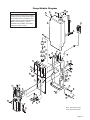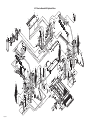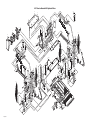
1
Service Manual for:
CA
Millennium
HZg^Zh
Public Use Wheelchair Lifts
Series A3
DOT — Public Use Lift
“DOT — Public Use Lift” verifies that this platform lift meets the
“public use lift” requirements of FMVSS No. 403. This lift may be
installed on all vehicles appropriate for the size and weight of the
lift, but must be installed on buses, school buses, and multipurpose passenger vehicles other than motor homes with a gross
vehicle weight rating (GVWR) that exceeds 4,536 kg (10,000 lb).
WARNING
Man
u
al
"Providing Access to the World"
®
®
Patent #5,261,779
Patent #6,599,079
32742 Rev. A
Patent #6,065,924
Patent #6,692,217
January
Patent #6,238,169
Patent #6,739,824
2008
Patent #6,464,447
Patents Pending
Read manual
before installing
or servicing lift.
Failure to do so
may result in
serious bodily
injury and/or
property damage.
Braun NL Series
International Corporate Hdqrs: P.O. Box 310 Winamac, IN 46996 USA
1-800-THE LIFT ®
(574) 946-6153
FAX: (574) 946-4670
Congratulations
We at The Braun Corporation wish to express our fullest appreciation
on your new purchase. With you in mind, our skilled craftsmen have designed and
assembled the finest lift available.
This manual provides service-related material. Refer to the FMVSS No. 403
Quick Reference Installation Sheet for installation instructions, operating instructions
and maintenance procedures.
Braun Millennium Series™ lifts are built for dependability and will provide years
of pleasure and independence as long as the lift is installed and serviced as specified
by a Braun certified technician, and the lift is operated by an instructed person.
Sincerely,
THE BRAUN CORPORATION
Ralph W. Braun
Chief Executive Officer
Warranty and Registration Instructions
Immediately upon receiving the lift, examine the
unit for any damage. Notify the carrier at once
with any claims.
Series No.
Pump Code
Model No.
Serial No.
Cylinder Code
OWNER'S WARRANTY REGISTRATION
NL917IB-A3-00025-56-14CG
Two warranty/registration cards (shown right) are
located in the lift-mounted manual storage pouch.
The sales representative must process one of the
cards. The consumer must fill out the other card
and mail it to The Braun Corporation. The warranty is provided on the back cover of this manual.
The warranty cards must be processed to
activate the warranty.
PURCHASED FROM
OWNER
DATE INSTALLED
NAME
ADDRESS
CITY
TELEPHONE
STATE
ZIP
TO VALIDATE WARRANTY
REGISTRATION CARDS MUST BE RETURNED TO THE BRAUN CORPORATION.
Sample Warranty/Registration Card
Two Braun Serial No./Series No. identification tags (shown below) are posted on the lift.
One I.D. tag is posted on the opposite pump side vertical arm. A second I.D. tag is located
on the opposite pump side tower. Both I.D. tags provide the product identification information provided on the warranty/registration card. Record the information in the space
provided (or document on a copy). This information must be provided when filing
a warranty claim or ordering parts.
The Braun Corporation
1-800-THE LIFT™
BRAUNLIFT.COM™
Model No.
DOT Public Use Lift MODEL#
NL917IB
Max. Lifting Capacity - 800 lbs.
Series No.
SERIAL NUMBER
A3-00025
PUMP CODE
CYLINDER
56
Serial No.
14CG
MFG DATE
01/04/06
Pump Code
e5*72/245*95/54*0110*00
PATENT
PENDING- 5,261,779-6,065,924-6,238,169-6,46
4,447-6,599,079-6,692,217-6,739,824
Sample Serial No./Series No. Identification Tag
Cylinder Code
Date of Manufacture
Contents
Troubleshooting
Certification Checklist Diagnostic Procedures ....... 2-3
Lift Electrical Schematic .............................................. 4
Lift Wiring Diagram ...................................................... 5
Switch and Sensor Locations ..................................... 6
LCD Lift Codes .............................................................. 7
Hydraulics
Hydraulic Schematic .................................................... 8
Notes .............................................................................. 9
Hydraulics Parts List .................................................. 10
Hydraulics Diagram .....................................................11
Repair Parts
Pump Module
Pump Module Parts List ....................................... 12
Pump Module Diagram ......................................... 13
Lift Exploded Views
42" Floor-to-Ground Lift Models
(NL915IB, NL915FIB, NL918IB, and NL918FIB)
Repair Parts List ................................................... 14
Exploded View........................................................ 15
48" Floor-to-Ground Lift Models
(NL916IB, NL916FIB, NL917IB, NL917FIB,
NL919IB and NL919FIB)
Repair Parts List ................................................... 16
Exploded View........................................................ 17
Notes ....................................................................... 18
Page 1
Certification Checklist Diagnostic Procedures
Use the following adjustment procedures should the lift not function as described in the certification checklist.
These procedures must be followed in order for the lift to be FMVSS 403/404 compliant.
• Vehicle movement is prevented unless the platform is fully stowed.
1. Verify lift stowed signal - pin 7 on the pump module has a +12 volt signal OR pin 9 has a ground signal
(depends on interlock used).
2. Refer to the interlock installation instructions.
• Lift operation shall be inhibited unless the vehicle is stopped and vehicle movement is prevented.
1. Verify vehicle secure signal (pin 6) has a +12 volt signal.
2. Refer to the interlock installation instructions.
• The platform will not fold/stow when occupied.
1. Position the platform at the floor level loading position.
2. Loosen the locknut on the dual relief valve adjustment (do not remove locknut). See illustration below.
3. Turn the adjustment screw counter clockwise until the platform does not fold when the Fold button is
pressed.
4. Turn the adjustment screw clockwise in 1/4 turn increments and press the Fold button until the platform
folds completely (Note: return the platform to floor level position after each attempt to fold the platform).
5. Turn the adjustment screw an additional 1/8 turn after the platform folds successfully.
6. Tighten the locknut without moving the adjustment screw.
7. Verify the platform will not stow while occupied.
Platform Relief Valve
Adjustment
(Located beside Backup Pump)
• The inner rollstop will not raise if occupied.
- Call Product Support
Page 2
Certification Checklist Diagnostic Procedures
• The outer barrier will not raise if occupied.
1. Lower the platform to the ground level loading position.
2. Remove the pump cover.
3. Turn the pressure adjustment screw (shown below) counter clockwise until the outer barrier does not raise
when the Up button is pressed.
4. Turn the pressure adjustment screw clockwise in 1/4 turn increments until the outer barrier raises and fully
locks in position when the Up button is pressed. DO NOT turn the pressure adjustment screw beyond this
position.
5. Verify the outer barrier will not raise when occuppied.
6. Reattach the pump cover.
Pressure
Adjustment
Screw
D
FOL
OLD
UNF
UP
N
DOW
• Verify platform lighting when lift is deployed.
1. Replace bulb(s) in the light housing.
2. Check fuse (5 amp fuse on circuit board; F13)
• An audio warning (and visual warning for public lifts) will activate if the threshold area is occupied when the platform is a least 1" below floor level.
1.
2.
3.
4.
Remove the threshold warning plate
Verify the threshold strip switch connectors are connected (see illustration on Page 6)
Replace the threshold strip switch
Reinstall the threshold warning plate
• Lowering the platform beyond the inner rollstop locking position is allowed only when the inner rollstop is locked
in position.
- Call Product Support.
• Lift platform movement shall be interrupted unless the outer barrier is raised and the outer barrier latch is positively engaged.
- Call Product Support.
Page 3
Lift Electrical Schematic
BK/WH(24 GA SILVER)
N
J15
S
C
NO
C6
1
2
3
4
1 1
2 2
3 3
WH
BU
BK
RD
OR
GN
RD
OR
GN
FRONT PUMP
ONLY
P26
J26
1 1
2 2
3 3
WH
BU
BK
WH(20)
VT(20)
YL(26)
RD(26)
GN(26)
1 1
2 2
J25
BU(16)
2
2
12 12
1
1
3
3
6
6
5
5
4
4
7
7
8
8
9
9
10 10
11 11
C
NO
NC
RD
BK
GN
RD
BK
GN
BK
RD
P3
5
4
3
2
1
6
GY/RD(18)
BU(16)
BU(16)
DESCRIPTION
SYMBOL
BATTERY
LIFT POWER SWITCH
GN(20)
WH(20)
J27
1 1
2 2
3 3
J3
J8
5
4
3
2
1
6
1 1
2 2
P4
J9
6
5
4
3
2
1
6
5
4
3
2
1
WH(20)
BK(20)
RD(20)
GN(20)
BK(20)
RD(20)
GN(20)
WH(20)
BU(20)
OR(20)
BK(20)
YL(20)
RD(20)
GN(20)
1 1
2 2
3 3
GN(20)
RD(20)
YL(20)
GN
RD
OR
BK
P5
3
8
6
7
5
4
1
2
J13
J4
RD(20)
BK(20)
GN(20)
WH(20)
P7
1
2
3
4
18
15
13
14
7
12
10
11
17
8
9
6
4
5
16
3
1
2
P6
6
5
4
3
2
1
6
5
4
3
2
1
J6
1 1
2 2
1 1
2 2
J31
P27
P25
P8
BK(20)
RD(20)
P31
YL(26)
RD(26)
GN(26)
BRIDGE
MICROSWITCH
BK(20)
BU(16)
RD(20)
BN(20)
WH(20)
PK(20)
NO
WH(20)
S
J16
GN(20)
RD(14)
C
J16
GY/RD(18)
BK(20)
N
J26
P16
P16
GY/RD(18)
C5
NC
STOW INTERLOCK (-)
MICROSWITCH
(GROUND)
1
2
3
4
5
6
7
8
9
BK(20)
GN(20)
STOW INTERLOCK (+)
MICROSWITCH
OR
J21
1
2
3
4
5
6
7
8
9
S
ROLL STOP
LATCHED
SENSOR
MAGNET
LIFT CONTROL MODULE
RD(18)
BK(18)
INTERLOCK
P21
MAGNET
BK(18)
RD(18)
BU(32)
YL(32)
GN(32)
RD(32)
BK(32)
WH(32)
J20
1 1
2 2
P27
ROLL STOP
RAISED
SENSOR
N
J7
P20
BK(18)
RD(18)
3
2
1
4
J20
2 2
1 1
3
2
1
4
BK(18)
BK(18)
P20
P13
GN
WH
BK
RD
RD
RD(18)
BK(18)
J2
6
5
4
3
2
1
6
5
4
3
2
1
WH(32)
BK(32)
RD(32)
GN(32)
YL(32)
BU(32)
P2
BK(18)
BK(18)
NC
P26
J27
OR
WH
BK
WH
BK
VT(20)
WH(20)
C
18
15
13
14
7
12
10
11
17
8
9
6
4
5
16
3
1
2
WH
GN
C1
NO
J5
2 2
1 1
RD
BK
WH
GN
BK(20)
OR(20)
BU(20)
J15
IB OCCUPANCY
MICROSWITCH
3
8
6
7
5
4
1
2
P15
PLATFORM LIGHTS (OPTION)
LIFT STOWED SIGNAL YL/LT. BU(20)
OR
RD
GN
PRESSURE
SWITCH
32651
(+12V INPUT)
(+12V OUTPUT)
P28
1 1
2 2
3 3
P15
THRESHOLD
SENSOR
BK/WH(24 GA SILVER)
BK(24 GA COPPER)
VEHICLE SECURE SIGNAL GY/RD(18)
J28
RD
1 1
2 2
J32
UP
YL(26)
RD(26)
GN(26)
1 1
2 2
STOW
P32
DOWN
MAGNET
BK
DOOR
IB RAISED
SENSOR
BK(24 GA COPPER)
NOTE: ALL WIRES ARE 22 GA.
UNLESS OTHERWISE NOTED.
P9
LIFT
SWITCH BOX
CHASSIS GROUND
NC
CIRCUIT BREAKER
CONNECTORS
JUNCTION
M
MOTOR
SOLENOID
SOLENOID
SWITCH
BRIDGE
SOLENOID
GN(14)
RD(2)
RD (2)
POWER
STUD
RD
BK
GN
FLOOR LEVEL
MEMORY SET
PUSH BUTTON
PK(20)
RD
BK
J30
F
E
D
C
B
A
F
E
D
C
B
A
BK
DIODE
00000
RD
BK
GN
E
COUNTER
PRESSURE SWITCH
GN
LED
+
COUNTER
-
E
MAGNETIC SWITCH
LIGHT
BEEPER
GN(20)
ROTARY POSITION SENSOR
Page 4
00000
MAGNET
N
S
NL917-A3-025.ai
(CIRCUIT BREAKER)
INTERLOCK
LED
GN(20)
CIRCUIT
SENTRY
GN(20)
(UP)
THRESHOLD
WARNING
LIGHT
NEG. -
POS.+
ROTARY
POSITION
SENSOR
GN(20)
DUAL RELIEF
SOLENOID
GN(20)
HYDRAULIC
PUMP BODY
GROUND
THRESHOLD
WARNING
BEEPER
BU(16)
RD(14)
LT. GN / GN(18)
M
BK(6)
RD(20)
PUMP BODY
GROUND
PUMP
RD(4)
GN(20)
GN(20)
BK(4)
WH(20)
BK(18)
RD
NC
RD(20)
GN(20)
NO
C
MICROSWITCH
WH(20)
DOWN
SOLENOID
GN(20)
UP/FOLD
SOLENOID
Lift Wiring Diagram
985-A1534NA
BK(18)
BK(18)
BK(18)
BK(18)
Platform Lights (Option)
Note: All wires 22 GA.
unless otherwise noted.
P20
P20
J20
J20
2 1
4
3
2
1
FS19
Pressure
Switch
BK
FS18
RD
915-2535NA
COLOR
8-COND WIRE CODE
1
RED
2
BLACK
3
WHITE
8
7
6
5
4
GREEN
4
3
2
1
5
NOT USED
6
NOT USED
NO.
COLOR
NO.
COLOR
1
ORANGE(20)
5
NOT USED
2
BLUE(20)
6
NOT USED
3
RED
7
NOT USED
4
BLACK(20)
8
BLACK
P6
P13
P5
18 17 16 15 14 13 12 11 10
RD(20)
BK(20)
RD(20)
BK(20)
2 1
5
6-COND WIRE CODE
NO.
2 1
2 1
6
8
9
7
6
5
4
3
2
1
18-COND WIRE CODE
4
5 6
7
7
8 9
NO.
COLOR
1
NOT USED
1
NOT USED
NOT USED
2
3
NOT USED
3
NOT USED
4
NOT USED
4
NOT USED
5
NOT USED
5
NOT USED
YL / LT. BU(18) +12V SIGNAL
6
7
GRAY / RED(18)
BLACK(20)
NOT USED
8
NOT USED
9
WHITE(20)
GRAY / RED(18)
YL / LT. BU(18) GROUND SIGNAL
NO.
3
J9
BK(20)
RD(20)
P16
J7
NOT USED
2
RED(20) & GREEN(20)
3
BLACK(20) & WHITE(20)
4
GRAY / RED(18)
J16
1
2
1
2
P16
N.O.
COM
NO
NC
N.C.
C-H
P9
WH(20)
FS5
FS6
GY/RD(18)
Lift Power
Switch
Stow Interlock (+)
Microswitch
C5
J31
P31
GN(20)
COM.
WH(20)
N.O.
COM
NO
NC
N.C.
3
4
4
3
1
2
2
1
4-COND WIRE CODE
C-H
12 11 10
9
8
7
6
3
2
1
5
4
10
YELLOW (20 GA.)
11
3
GREEN (20 GA.)
12
COLOR
GREEN
4
NOT USED
13
NOT USED
5
ORANGE JUMPER
14
WHITE
6
ORANGE JUMPER
15
BLACK
RED
Interlock LED
ORANGE
FS4
7
NOT USED
16
NOT USED
8
VIOLET (20 GA.)
17
NOT USED
9
WHITE (20 GA.)
18
NOT USED
NO.
COLOR
1
GREEN
2
RED
3
NOT USED
4
NOT USED
5
RED
6
7
BLACK
NOT USED
8
NOT USED
9
Stow Interlock (-)
Microswitch
3
2
1
6
5
4
6-COND WIRE CODE
12-COND WIRE CODE
985-2532NA
COM.
RD(20)
915-A2539NA
NO.
RED (20 GA. )
2
PK(20)
GN(20)
NO.
1 2 3
3 2 1
3-COND WIRE CODE
3-COND WIRE CODE
3 2 1
WHITE (20 GA.) & WHITE (20 GA.)
2
BROWN (20 GA.)
3-COND WIRE CODE
NO.
COLOR
NO.
COLOR
NO.
COLOR
NO.
COLOR
BLUE (16 GA.)
1
YELLOW (26 GA.)
1
RED
1
RED
1
YELLOW (20 GA.)
5
BLACK (20 GA.)
2
RED (26 GA.)
2
ORANGE
2
ORANGE
2
RED (20 GA.)
6
PINK (20 GA.)
3
GREEN (26 GA.)
3
GREEN
3
GREEN
3
GREEN (20 GA.)
RED
10
BLACK
11
GREEN
12
BLACK
Rollstop Extension
Roll Stop
Raised Sensor
P27
✸
✸
(Front Pump Only)
NL917FIB
NL918FIB
NL919FIB
(31208A)
J27
✸
30433A60
6-COND WIRE CODE
4-COND WIRE CODE
COLOR
NO.
COLOR
BLACK(20)
1
BLACK(20)
2
RED(20)
2
RED(20)
3
GREEN(20)
3
GREEN(20)
4
WHITE(20)
4
WHITE(20)
NO.
A
32365A
UNFOLD
FOLD
DOWN
UP
COLOR
BK
RD
NOT USED
C
NOT USED
D
GREEN
E
BLACK
F
RED
FS13
P26
30433A60
NOT USED
B
3-COND WIRE CODE
RED (20 GA.)
4
3
A B C D E F
1
1 2 3
COLOR
1
C6
NO.
FS7
P8
P4
J16
BK(20)
J21
P3
P7
985-0531NA
COLOR
1
BK(20)
GN(20)
GY/RD(18)
P21
J8
J4
RD(20)
1
2
1
2
NO.
Lift
Control
Module
1
2
BK(20)
31797A
J26
J27
✸
✸
P26
J26
Roll Stop
Latched Sensor
+ -
Counter
P27
NL915FIB
NL916FIB
(31551A)
FS14
E
FS12
Rotary
Position
Sensor
3-COND WIRE CODE
WH(20)
FS20
Floor Level
Memory Set
Push Button
-
BK
FS8
FS5
FS9
WH(20)
3-COND WIRE CODE
NO.
COLOR
NO.
COLOR
NO.
YELLOW (26 GA.)
1
WHITE
1
WHITE
1
BLUE (20 GA.)
2
RED (26 GA.)
2
BLUE
2
BLUE
2
ORANGE (20 GA.)
3
GREEN (26 GA.)
3
BLACK
3
BLACK
3
BLACK (20 GA.)
Bridge
Microswitch
RD
3-COND WIRE CODE
3-COND WIRE CODE
COLOR
1
Threshold
Warning
Light
+
Beeper
1 2 3
3 2 1
NO.
FS1
J30
Switch
Box
1 2 3
3 2 1
GN
COM
NO
31010RA - Rear Pump
31010FA - Front Pump
BU(16)
J25
P25
1
2
BU(16)
COLOR
1
2
NC
WH(20)
VT(20)
GN(20)
FS21
BN(20)
GN(20)
FS17
GN(20)
FS16
GN(20)
1
2
3
3
2
1
GREEN
BK
FS3
GN(16)
1
IB Raised
Sensor
Down
31030A45
J28
Circuit Sentry
(Circuit Breaker)
Bat.
GN(14)
J15
(Side view of
solenoids removed
from pump.)
IB Occupancy
Microswitch
1
BK
Dual Relief
COM.
COM
4
C-H
NO
N.O.
WH
NC
N.C.
C1
Aux.
BU(16)
FS11
GN(16)
Back
Plate
1
2
BK(24) COPPER
1
2
2
1
31221A
BK / WH(24) SILVER
P32
B
A
T
RD(2)
FS2
BK(6)
Threshold Sensors
J32
RD(2)
Motor Power Feed Wire
Down
Lift
Power Cable
205-0712-37
915-2530NA
Lead Wire
13362A
Bridge
Pump Ground
RL4
Power
Stud
Connects to
Vehicle Battery
(+) Positive Post
Dual
Relief
2
P28
BK(20)
RL3
2
P15
FS10
GN
RED
3
BK(24 GA COPPER)
COLOR
RD
ORANGE
2
GREEN(26)
WH
COLOR
1
RED(26)
3
BK / WH(24 GA SILVER)
Ground
NO.
YELLOW(26)
2
1
P15
or
Hydraulic
Pump
RD(20)
Note polarity of diode. It
must be oriented as shown.
Detail at left shows two different
styles of diode identification.
NO.
RD(20)
Bridge
26082A-4
RD(4)
BK(24 GA COPPER)
Pump Module
Power Feed
7
RL
3-COND WIRE CODE
J15
3-COND WIRE CODE
BK / WH(24 GA SILVER)
Up/Fold
Solenoid
RD(14)
26161A-84 BK(4)
YL/LT. BU(18)
31798A
LIFT STOWED SIGNAL
(Located in cavity #7 or #9 - see chart above)
J3
J13
J5
J6
COLOR
1
Interlock
Connection
GY/RD(18)
VEHICLE SECURE SIGNAL +12V INPUT
1
4-COND WIRE CODE
RD(20)
A
U
X
9
RL2
8
NOT USED
RL1
6
7
31033A54
COLOR
2
4
+ -
NO.
2
NL915IB/FIB
NL918IB/FIB
(31033A96)
9-COND WIRE CODE
NL916IB/FIB
NL917IB/FIB
NL919IB/FIB
(31033A99)
9-COND WIRE CODE
3
915-2533NA
1 2
4
9 8
GN(20)
1
6 5
RD(14)
3 2
Note: Shown with lift in stowed position.
BK / WH(24) SILVER
1
2
31221A
BK(24) COPPER
Page 5
Switch and Sensor Locations
Pressure Switch
31199
Threshold Strip Switch
31221A (Qty. 2)
*Stow Microswitch
23184 (Qty. 2)
D
FOL
OLD
UNF
UP
N
DOW
Inboard
Left
Right
Outboard
*Rotary Position Sensor
31194A
*IB Occupancy
Microswitch Assy.
31643A
*IB Raised
Magnetic Sensor
31030A45
*IB Raised
Magnet
30662
*Bridging
Microswitch
31010RA (Rear Pump)
31010FA (Front Pump)
Outer Barrier Latched
Magnet
30662
Outer Barrier Latched
Magnetic Sensor
30433A60
*Note: Mirror image for
right (front) pump lifts.
Page 6
Outer Barrier Raised
Magnetic Sensor
30433A60
Outer Barrier Raised
Magnet
30662
LCD Lift Codes
Listed below are codes that the lift controller outputs
during lift operation. The codes will be displayed on
an LCD screen located on the lift control board inside
the pump module. See the Manual Operating Instructions in the operator's manual for pump cover removal
instructions.
Non-Flashing Numbers
01 – Platform stowed
02 – Platform unfolding
03 – Platform unfolding paused
04 – Platform at floor level
05 – Platform beginning to lower
06 – Platform lowering (threshold cannot be occupied
from this point down)
07 – Outer barrier moving to horizontal position
08 – Platform at ground level
09 – Outer barrier moving to vertical position
10 – Platform raising
11 – Platform raising paused at floor
12 – Platform folding (limited pressure)
13 – Platform folding (full pressure)
14 – Timed fold (cinching lift tite) or (anti-rattle state)
15 – Platform folding stopped
16 – Paused fold
17 – Platform between ground and 3” above ground
18 – Platform above 3”
19 – Outer barrier moving to horizontal postion
28 – Illegal function/not defined
29 – Interlock fault not recognized (or has been cleared
but a motion button is still pressed)
30 – Platform location unknown
31 – Platform location transition state; attempting to
locate position
35 – Two or more motion buttons are being pressed
36 – The retention belt cannot be buckled while trying
to fold or unfold
37 – Motion button being pressed is not a valid motion
50 – Outer barrier is not up above inboard barrier
locked position
51 – Threshold is occupied when platform is 1” or more
below floor level
52 – Inner rollstop is not up and locked below inner
rollstop locked position
53 – Inner rollstop occupied sensor is not activated
between floor and inner rollstop up position
54 – Outer barrier is occupied before it is up
55 – Outer barrier is not latched when above the inner
rollstop locked position (Millennium only)
56 – Outer barrier is not up and latched and bridge
switch did not deactivate
57 – Outer barrier is not up and latched and ground
detect switch did not deactivate (Century and Vista
only)
58 – Outer barrier is not up and latched and the platform
is 3” above the ground
59 – Outer barrier is not up after pausing platform travel
60 – The kickout gas springs are worn, replace before
using
75 – Low voltage detected; must turn off power switch to
reset LCD
77 – Vehicle secure interlock has not been activated
90 – Position will be set if you keep holding the button
until it beeps
91 – Position is out of a predetermined acceptable range
of floor position
92 – Bridge switch is not made, needs adjusting
93 – Inner rollstop occupied switch is not made, position
needs to be moved or switch should be adjusted
94 – Outer barrier is not made, fix and try again
95 – Outer barrier latch is not made (check for jumper on
Century and Vista lifts, check latch on Millennium
lifts)
99 – Controller program is not valid; replace controller
Flashing Numbers
Flashing 65 – Unfold button is pressed
Flashing 66 – Fold button is pressed
Flashing 67 – Down button is pressed
Flashing 68 – Up button is pressed
Flashing 69 – Bridge switch is activated
Flashing 70 – Outer barrier latch switch is activated
Flashing 71 – Ground detect switch is activated
Flashing 72 – Outer barrier up switch is activated
Flashing 73 – Inner rollstop up switch is activated
Flashing 74 – Inner rollstop occupied switch is activated
Flashing 76 – Outboard barrier occupied switch is
activated
Flashing 78 – Threshold tape switch “A” is activated
Flashing 79 – Threshold tape switch “B” is activated
Flashing 80 – Position set button is pressed
Page 7
Hydraulic Schematic
.50 GPM
Roll Stop Fold
Pressure Switch
Bridging
Valve
Orifice
Orifice
Lifting
Relief Valve
Down
Valve
Secondary
Valve
2500
PSI
1900
PSI
Opposite
Pump
Cylinder
BACKUP
PUMP
Description
Folding
Relief Valve
PUMP
Symbol
Fixed Displacement
Pump
Pump Motor
Description
Hydraulic Port
M
Roll Stop
Cylinder
Pump Side
Cylinder
800
PSI
2 Way 2 Position
Solenoid Valve
Backup Pump
Pressure Compensated
Flow Control
Single Acting Cylinder
Relief Valve
Check Valve
Filter Screen
Unfold Orifice
Vented Reservoir
Manual
Shutoff Valve
Orifice
Pressure Switch
Page 8
M
Symbol
NOTES
This page intentionally left blank to provide a place for notes and references.
Page 9
Hydraulics Parts List
Part Numbers of Items Dedicated per Lift Model (Front and Rear Pump Models)
Item Qty.
1
1
Description
Hose Assembly, 1/8” (Opposite Pump Side)
NL915
NL916
NL917
NL918
NL919
16004A-081
16004A-079
16004A-086
16004A-084
16004A-087
16004A-046
2
1
Hose Assembly, 1/8” (Pump Side)
16004A-046
16004A-046
16004A-046
16004A-046
3
2
Cylinder ✓
C1514.3-9407
C1514.3-9408
C1514.3-9408
C1514.3-9407 C1514.3-9408
4
1
(Rear Pump) Hose Assembly, 3/16” w/Two Guards
915-2601-123 915-2601-139 915-2601-139 915-2601-123 915-2601-139
5
1
(Front Pump) Hose Assembly, 3/16” w/Two Guards
6
1
(Front Pump) Hose Assembly, 3/16”
915-5602-92.5
915-5602-92.5
915-5603-80.5 915-5603-83.5
915-5602-82
915-5603-86.5
915-5602-82
915-5602-92.5
915-5603-83.5 915-5603-86.5
Part Numbers of Items Identical on all Lift Models (Front and Rear Pump Models)
Item Qty.
Description
Part No.
31038-12V
7
1
Pump Assembly (M268-0113)12V - with Reservoir/with Backup Pump)
8
1
Solenoid, 4-Post (See Pump Module Exploded View for Solenoid Selection)
9
1
Power Cable, Up Solenoid to Motor
10
1
Motor, Pump - 12 Volt - Low RPM
31350
11
1
Elbow, 65° - Male 7/16-20 SAE O-Ring to 7/16-20 SAE O-Ring Boss
26578
12
2
Valve Assembly, “Down / Bridge” (complete)
13
3
Coil (only), “Down / Bridge” Valve - (shown below)
31122
14
2
Cartridge (only), “Down / Bridge” Valve - (shown below)
26078
15
1
Valve Assembly, “Duel Relief” (complete)
31120K
16
1
Cartridge (only), “Duel Relief” Valve - (shown below)
31121
17
1
Cap, Reservoir Filler
16935
18
4
O-Ring (only), Hand Pump Mounting
17351
19
1
Hand Pump (Backup) with O-Rings (Item 18)
26074
20
3
Screw, 1/4-20 x 2-1/4”, Allen Head
26080
21
1
Clamp, Reservoir - H-48 (M259)
17069
22
1
Reservoir, Hydraulic Fluid
16934
23
1
Fitting, 90° - 1/8” NPT x 1/8” Barb - Plastic
87563
24
1
Switch, Pressure, 7/16-20 SAE O-Ring Male
31199
25
2
Fitting, Male 7-16-20 SAE O-Ring to Male 7/16-20 JIC 37°
24504
26
1
Elbow, (1) Female 7/16-20 JIC 37 Swivel - (2) Male 7/16-20 JIC 37°
26579
27
2
Elbow, 90°, 7/16-20 SAE O-Ring Male - 7/16-20 JIC 37° Male, Orifice
26667
28
2
Elbow, 90°, 1/4” NPT Male to 1/4” Barbed
15150
29
1
Hose, Thermal Plastic - Black, 1/8” I.D.
30
1
Connector, Plastic “Y”, 1/8” O.D.
18877
31
1
Fitting, 90° - Male 9/16-18 SAE O-Ring to Male 7/16-20 JIC 37°
87622
32
1
Cylinder, Roll Stop (complete 915-3318NA contains items 31, 32, & 35)
33
1
Handle with Grip
34
1
Diode Assembly, Up Solenoid
73906A
35
1
Breather Vent, 1/4” NPT
26200-2
36
1
Kit, Hydraulic Port Service Cap
27049K
✓ Seal Kits: If repairing a cylinder, order Seal Kit #1500-0500P.
* Raw material items ordered and priced per inch (order specified length).
29049
31348K
23742R*
25309NA
17206A
12
“Down and Bridge”
Valve (complete)
“Duel Relief”
Valve (complete)
13
13
Coil
#31122
Coil
#31122
14
Cartridge
#26078
Page 10
15
16
Cartridge
#24612
7
36
3
6
FRONT PUMP
Hydraulics Diagram
3
Hydraulic
Repair
9
For repair of a
hydraulic hose
or cylinder, read
this.
Service
Bulletin
27049
5
34
32
10
11
12
27
REAR PUMP
25
FRONT PUMP
8
24
33
4
27
15
17
Roll Stop Cylinder
31
18
35
26
19
20
21
Manual
Backup
Pump
23
22
Hydraulic
Pump
29
28
30
1
2
Pump Side Cylinder
Opposite Pump Side Cylinder
25
28
29
29
Page 11
Pump Module Parts List
Part Numbers of Items Dedicated per Lift Model
Item
1
2
3
Qty.
1
1
1
1
Description
Pump Module (complete), 12 Volt, Rear
Plate, Backing / Mounting - Rear
Cover, Pump, 2-Piece - Back (915-0513RNA or 915-0513FNA Includes Items 2 and 16 - 22)
Cover, Pump - 2-Piece - Top / Front (915-0519RNA or 915-0519FNA Includes Items 3 and 38 - 51)
Item
4
5
6
7
8
9
10
11
12
13
14
15
16
17
18
19
20
21
22
23
24
25
26
27
28
29
30
31
32
33
34
35
36
37
38
39
40
41
42
43
44
45
46
47
48
49
50
51
52
53
54
55
56
57
Qty.
1
1
1
1
2
2
1
1
1
1
8
1
1
1
1
1
1
1
3
1
1
1
2
2
2
1
1
1
1
1
1
1
1
1
3
1
1
1
1
1
1
1
1
1
1
1
1
1
1
1
1
1
1
1
Description
Pump Assembly (M268-0113) 12V-120G - Dual Relief / ARS (Includes Items 5 & 6)
Power Cable, Up Solenoid to Motor
Solenoid, Up - 4-Post - Trombetta (Flat Mount)
Diode Assembly, Up Solenoid
Nut, #10-32, Serrated Flange
Fitting, Male 7/16-20 O-Ring to Male 7/16-20 JIC 37°
Elbow, Female Swivel 7/16-20 JIC 37° to (2) Male 7/16-20 JIC 37°
Switch, Pressure
Control, Hand Pendant Assembly - Standard
Control Board Assembly
Standoff, Snap-In
Switch, Push Button
Recepticle, Clip On
Lens, Threshold Warning - Red
Decal, Warning / Pressure Relief Valve (Not shown - see Decal Section)
Spacer, Lens - NHTSA
Metal Ring Base - Lamp
Socket, Lamp
Screw, #8-32 x 1/2” Pan Head Phillips - Thread Cut
Bulb, Light
Diode, Green LED, Panel Mount
Strain Relief - Liquid Tight
Washer, 5/16” Flat
Bolt, 5/16-18 x 3/4”, Nylock, Hex * See note below
Bolt, 5/16-18 x 1/2”, Nylock, Hex * See note below
Cable, Ground
Washer, 5/16” External Tooth
Beeper, Continuous
Switch, Toggle
Decal, Lift Power - On/Off (Not shown - see Decal Section)
Stud, Power Feed
Rubber Boot, Red tSee note below
Harness, Lift Interlock Connection
Pump Handle with Grip
Rivet, Pop, SD43BS - 1/8” - .13”/.19”
Plug, Window - Clear
Stud, Wing Head - 1/4 Turn
Retainer, Push On
Washer, Nylon, 1/4” I.D. x 11/16” O.D. x .030”
Clip, Pump Handle - Top
Clip, Pump Handle - Bottom
Wire Assembly, Lift Stowed Connection tSee note below
Decal, Manual Instructions - Public (Not shown - see Decal Section)
Decal, Removal / Installaton - Pump Cover (Not shown - see Decal Section)
Decal, Warning - Control Board Damage - ESD (Not shown - see Decal Section)
Decal, Removal / Installation Pump Handle (Not shown - see Decal Section)
Decal, Installation & Warning - Hydraulic Pressure Switch (Not shown - see Decal Section)
Decal, Dual Relief Adjustment (Not shown - see Decal Section)
Cable, Pump Module Power Hookup (Not shown - see Wiring Diagram)
Harness, Power - Stow Interlock (Not shown - see Wiring Diagram)
Harness, Interlock / Lighting (Not shown - see Wiring Diagram)
Harness, Up / Down Solenoid (Not shown - see Wiring Diagram)
Harness, Threshold Switch Extension (Not shown - see Wiring Diagram)
Harness, Stow Interlock (Not shown - see Wiring Diagram) tSee note below
NL915IB, NL916IB,
NL917IB, NL918IB
and NL919IB
NL915FIB, NL916FIB,
NL917FIB, NL918FIB
and NL919FIB
917-A3516RNA
985-2501RN
915-0513RN
915-0519RN
917-A3516FNA
985-2501FN
915-0513FN
915-0519FN
Part Numbers of Items Identical on all Lift Models
Part No.
31038-12V
29049
31374
73906A
83080
24504
26579
31199
32365A
100159-001
31011
31753
28803
30704
22249
31386
30971
30703
30974
19841
29545
30753
10063
29608
10012
22166A
16368
30487
31787
21494
26084
82046
31797A
17206A
12954
30443
28804
28805
12690
915-5517
915-5518
31798A
31412
29051
30787
29052
27154
32201
26082A-4
915-2530NA
985-0531NA
915-2533NA
985-A1534NA
915-1538NA
* Apply red #271 Thread Locker Loctite® to the four hex bolts (items 27 and 28) if a blue nylon patch is not present on
the bolts when retrofitting an M268-0113 pump assembly. Loctite® is available from The Braun Corporation under part
number 11522.
t Indicates items available for replacement part purposes only. These items are not included with replacement pump
modules.
Page 12
Pump Module Diagram
42
Pump Mounting Bolts
39
38
Apply red #271 Thread Locker Locktite®
to the three pump mounting bolts (items
27 and 28) if a blue nylon patch is not
present on the bolts when retrofitting an
M268 pump assembly. Loctite® is
available from The Braun Corporation
under part number 11522-1.
43
40
41
37
3
12
UN
FO
LD
FO
DO
W
LD
N
UP
44
323
53
38
17
23
19
24
20
2
16
22
25
21
13
27
26
28
14
29
30
15
31
32
1
4
9
34
35
5
11
8
45
36
7
28
6
8
9
10
Note: Rear pump shown,
front pump mirror image.
Page 13
42” Floor-to-Ground Lift Repair Parts List
Item
Qty.
1
2
3
4
5
6
7
8
9
10
11
12
13
14
15
16
1
1
1
1
1
1
1
1
1
1
1
1
1
1
1
1
Item
Qty.
17
18
19
20
21
22
23
24
25
26
27
28
29
30
31
32
33
34
35
36
37
38
39
40
41
42
43
44
45
46
47
48
49
50
51
52
53
54
55
56
57
58
59
60
61
62
63
64
65
66
67
68
69
70
71
72
73
74
75
76
77
78
79
80
81
82
83
84
85
86
87
88
89
90
91
92
93
94
95
96
97
98
99
100
101
102
103
104
105
4
4
2
2
1
6
1
1
1
1
10
10
1
1
4
1
2
2
2
1
1
2
1
5
4
1
1
2
2
1
2
2
1
2
1
16
8
1
1
2
6
1
2
8
4
2
2
2
2
6
4
2
2
1
2
2
8
10
2
2
2
4
2
2
2
2
1
2
6
2
2
2
2
2
10
2
2
6
2
2
1
6
2
2
2
2
2
2
2
Description
Part Numbers of Items Dedicated per Lift Model
NL915IB
Base Weldment
Cover, Pump, 2-Piece, Back-Bottom
Cover, Pump, 2-Piece, Top-Front Assy.
Platform Weldment
Outer Barrier Assembly (inc. 5,16,31,168,179)
Inner Rollstop
Bridge Switch Assembly
Block, Platform Stop
Block, Platform Stop
Plate, Backing/Mounting
Base Cover Assy., (Traction Tape Not Shown)
Parallel Arm Assy., Bottom, w/Bearings - Rear
Parallel Arm Assy., Top, w/Bearings - Front
Parallel Arm Assy., Top, w/Bearings - Rear
Parallel Arm Assy., Bottom, w/Bearings - Front
Rubber Nose
NL915FIB
915R3142NW30
915-0513RN
915-0519RN
917-03050NW
915-0312NA30Y
918-0147NWY-30
31010RA
25778
900-0311
985-2501RN
915-5142CNA30Y
915-0457RNA
915-0422FA
915-0422RNA
915-0457FNA
24603-30
NL918IB
915F3142NW30
915-0513FN
915-0519FN
917-03050NW
915-0312NA30Y
918-0147NWY-30
31010FA
900-0311
25778
985-2501FN
915-5142CNA30Y
915-0457FNA
915-0422FNA
915-0422RA
915-0457RNA
24603-30
918R3142NW33
915-0513RN
915-0519RN
917-03350NW
915-0312NA33Y
918-0147NWY
31010RA
25778
900-0311
985-2501RN
915-5142CNA33Y
915-0457RNA
915-0422FA
915-0422RNA
915-0457FNA
24603-33
NL918FIB
918F3142NW33
915-0513FN
915-0519FN
917-03350NW
915-0312NA33Y
918-0147NWY
31010FA
900-0311
25778
985-2501FN
915-5142CNA33Y
915-0457FNA
915-0422FNA
915-0422RA
915-0457RNA
24603-33
Part Numbers of Items Identical on All Lift Models
Page 14
Description
Snap-Ring 5/16"
O-Ring, 5/16" I.D. x 1/16" O.D.
Screw, Socket Head, 3/8-16 x 1/2" with 1/2" Shoulder
Grommet, I.D. .281"/ FR.125" x GD.625"/T.375"
Pivot, Outer Barrier Lever
Rivet, Pop, 1/8"- .13"/.19"
Stud, Wing Head
Retainer, Push-On
Grommet, ID .312", FR .250", GD .813" T500"
Pump Assembly
Pin, Pivot, Parallel Arm
Screw Drive #8 x 3/16" Long Black
Receptacle, Clip-On
Cylinder Assy., Outer Barrier
Snap-Ring 1/2"
Latch Assy., Outer Barrier
Bolt, 5/16-18 x 1/2" Nylock, Hex
Washer, 5/16" Flat
Bolt, 3/8-16 x 1/2" Nylock, Hex
Assembly, IB Occupied
Assembly, Rotary Position Sensor
Bolt, 5/16-18 x 3/4" Nylock, Hex
Rivet, Pop, SD68 BSLF-3/16" - .38"/.50"
Rivet, Pop, 1/8"- .25"/.31"
Bearing, Flange, 1/2" x 1/4"
Weldment, Latch, Lift/Tite, Rear
Weldment, Latch, Lift/Tite, Front
Screw, #4-40 x 5/8", Round Head
Screw, 1/4-20 x 3/4", Flat Head, Countersink
Screw, #8-32 x 1", Mach. Truss Head
Nut, #4-40 w/Lockwasher
Nut, #8-32, Hex
Bag, Vinyl - 7" x 10"
Cylinder, 14.625"/29.146" Retracted
Screw, 10-32 x 5/8" Pan Head Phillips, Thd. Cut
Bearing, Flange, 3/4" x 3/8"
Bushing, 3/4" I.D. x 1/2"
Vertical Channel Weldment, Front, 48"
Cover, Plastic, Parallel Arm, O/S Front-w/Tape
Tape, 1" Wide S-Face Foam, x 14" (1 Shown)
Tape, 1" Wide S-Face Foam, x 10" (3 Shown)
Cycle Counter-LCD Without Reset
Handrail Weldment
Rivet, Push In - 8MM
Bumper, Rubber, 31/32" O.D.
Screw, #8-18 x 1/2", Self-Tap, Phillips
Bulb, Light 20-W, Halogen Reflector
Nut, #10-32 w/Lockwasher
Screw, 1/4-20 x 3/4", Button Head, Socket Cap
Washer, 3/8" Flat, Black
Nut, 3/8-16, Hex Lock
Cotter Pin, 1/4" x 2", Black
Nut, 1/4-20 Hex Lock
Cover, Plastic, Parallel Arm, I/S Front-w/Tape
Threshold Strip Switch
Bolt, Shoulder, 5/16" x 5/8"-1/4-20
Washer, .516" I.D. x 1" O.D. x .0269", Auto BK
Washer, 1/2" Flat Black Zinc
Bolt, 3/8-16 x 1", Hex
Washer, 3/8", Lock, Black
Lever, Inner Rollstop
Clamp, Insulate, 1 3/8" I.D.
Washer, 5/16" Lock, Black
Gas Spring, Fold Arm
Ball Stud, Gas Spring, 13MM x 3/8-16 F. Thread
Washer, 3/8", Lock
Spacer, Flap Cylinder .184" Thick
Clip, Safety, 3/8-16 x 3/4", Flange
Bolt, 3/8-16 X 3/4", Flange Button Head, Socket Cap
Bolt, 5/16-18 x 2", Flange, Hex
Nut, 5/16-18, Serrated Flange
Arm, Slide Support (Replace In Pairs)
Slide, Platform, Rotate, Weldment
Spacer, .5" O.D. x .334" I.D. x 1.515" LG
Bearing, Flange, 3/4" x 1/4"
Weldment, Platform Pivot Arm - 42" (Replace In Pairs)
Pin, Pivot, Lower Arm
Ring, Snap, 3/4", External
Bearing, UHMW, Flat, 1.226"
Ball Stud, 10MM
Vertical Channel Weldment, Rear
Plastic End Cap, 1" I.D. x 1 1/4" O.D.
Grip, Handle, Yellow
Spring, Dampener, Retract
Bolt, 5/16-18 x 1 1/4" Low Socket Hd., Cap, Bk.
Bumper, 1" x 1/2" Long
Screw, 1/2-20 x 1 1/2" Set Lock, Black
Block, Guide-Platform Stow
Pin, Platform
Part No.
Item
Qty.
24570
26614
25929
27725
24550
12954
28804
28805
27726
31038-12V
917-0403
31086BK
28803
915-3318NA
13273
915-4343NA
10012
10063
29729
31643A
31094A
29608
15244
13906
24442
27013RW
27013FW
14810
28986
19912BK
19537
10777
31174
C1514.3-9408
26714
24011
900-0456
955-0448FNW
915-0704NA
82015R014
82015R010
30547
985-0618NW
30063
10950
13583
31060
18349
81068-000
10064
13617
15886BK
10775
915-0701NA
31221A
31816
15328
25346
10025
10069BK
985-0404N
29765
10068
29186
29185
10069
915-0416
12608
25171
25130
25131
985-6612N
915-0606N
25132
24012
918-2640NW-BKN
900-0413N
18657
205-1760
21301
955-0448RNW
20474
19074
26963
26327
33654
18663
28593
975-2325
106
107
108
109
110
111
112
113
114
115
116
117
118
119
120
121
122
123
124
125
126
127
128
129
130
131
132
133
134
135
136
137
138
139
140
141
142
143
144
145
146
147
148
149
150
151
152
153
154
155
156
157
158
159
160
161
162
163
164
165
166
167
168
169
170
171
172
173
174
175
176
177
178
179
180
181
10
2
1
2
2
2
3
4
2
3
2
4
1
1
1
2
1
2
1
1
4
1
1
2
2
4
3
2
6
1
2
4
8
2
2
2
2
2
2
2
6
2
11
4
1
1
4
2
1
1
2
4
2
4
4
4
2
2
2
4
2
2
1
1
4
1
1
1
3
4
1
1
3
2
1
3
Description
Screw, 5/16-18 x 3/4", SHFS
Spacer, UHMW, Vertical Channel
Position Sensor Collet
Bracket, Mounting, Quiet Ride
Gas Spring, 12.2" Extended/8.3" Compressed
Bolt, 5/16-18 x 3/4", Carriage, Black
Washer, 5/16", External Tooth
Nut, 5/16-18 Hex
Bracket, Inner Side Panel Guide
Bearing, UHMW, Flat, Thin, Black
Pivot, Inner Rollstop Lever, Upper, Inside
Bearing, Flange - 3/4" x 1/2"
Spacer, UHMW, Latch
Spring, 1/4" x 1" Extension w/Hooks
Tubing, Polyurethane - 1/4" I.D. x 1/2" O.D. x .81"
Pin, Clevis, 3/8" x 3", Black
Pin, Platform Cylinder
Ring, Snap, 1/2", External, .035" Thick
Weldment, Tube-IB Fold Arm-Rear
Lever, Outer Barrier Latch (Assembly #915-0345A)
Nut, 3/8-16, Hex, Lock, Jamb
Weldment,Tube-IB Fold Arm-Front
Pivot, Outer Barrier Cylinder, Front
Bolt, 5/16-18 x 1 1/2" Hex Head, Cap
Bolt, 7/16-20 x 1", SHCS, w/Nylock Patch
Screw, #10-32 x 3/8", Flat Head, Hex
Adapter, Cylinder/Outer Barrier Lever-Out
Bolt, 5/16-18 x 3/4", Button Head, Soc Cap Hd
Rivet, Pop, 3/16"-.25"/.38", Black
Adapter, Cylinder/Outer Barrier Lever
Harness, Sensor - Cherry w/Plug
Rivet, Snap, Black, .158/.197 Thick
Clip, Cable, 1/2", Plastic
Nut, 5/16-18, Top Lock, Black
Bolt, 1/4-20 x 1/2", Button Head Socket
Bolt, 3/8-16 x 2", Hex Head, Cap
Roller Assembly
Roller Retainer
Nut, 5/16-18 Hex, Lock
Pivot, Inner Rollstop Lever, Upper-Outer
Clamp, 1/4" I.D.- Nylon Loop
Clip, Hand Control Hanger
Rivet, Snap, .201" x .256"/.295"
Bearing, Flange, 1" x 1/2-16 FDU08
Cover, Plastic, Parallel Arm, O/S Rear-w/Tape
Weldment, Inner Rollstop Bracket, Front
Spacer, Handrail, .375” Thk. UHMW
Washer, .516" I.D. x .75" O.D. x .250", Black
Cover, Plastic, Parallel Arm, I/S Rear-w/Tape
Weldment, Inner Rollstop Bracket, Rear
Spring, Torsion - .366 I.D. x .05"
Spacer, IB Lock
Weldment, IB Lock
Bearing, 3/8" I.D. x 1/2" Long
Roller, .65" O.D. x 1/2" Long
E-Clip, 3/8" Shaft
Spacer, Handrail, .230" Thk. UHMW
Bolt, 1/4-20 x 1", Hex
Nut, 1/4-20, Hex
Washer, 1/4", External Tooth
Bearing, Flange, 3/8" x 1/4" - Plastic
Light Assy, Vertical Channel
Tab, Outer Barrier - Assembly
Washer, .4" I.D. x .810" O.D. x .12"
Spacer, UHMW-.75" O.D. x .39" I.D. x .25"
Bolt, 3/8-16 x 3/4" Soc. Hd. Cap Screw Bk.
Spacer, Flap Cylinder .700" Thick
Guard, Outer Barrier Sensor Wires
Washer, Finger, Disc Spring
Screw, #10-32 x 1/2" Button Head, Socket, Cap
Position Sensor Spacer
Slide, UHMW, Platform Rotate
Rivet, Pop, 3/16" - .13/.25" - SD64BS
Rivet, Pop, 3/16" x .06"/.13"
Adapter, Cylinder/Outer Barrier Lever
Washer, #10, Flat, Auto BK
Part No.
25527
995-0320
31093
915-0392
30550A
15858BK
16368
10058
915-0703
916-5406
916-5433
24027
950-7760
10774
28630R000.81
24932BK
915-0414
20946
985-0625RNW
915-0435
20926
985-0625FNW
990-0352
10014
28474
24537
990-0341
24440
14993
915-0341N
30433A60
25759
10092
28324BK
15733
10027
1000-2395A
915-5353
11387BK
916-5434
84396
84389
26362
28031
915-0702NA
985-0431FNW
995-0301
25336
915-0703NA
985-0431RNW
30386
30394
985-0630NW
30405
985-0631N
84383
911-5301
10001
10057
83588
24028
31062A
915-6367NA
24536
30227
26259
915-0415
915-0368N50Y
27276
30375WP
31092
31677
11513
11512
915-0344
11541
42” Floor-to-Ground Lift Exploded View
98
36
52
112
109
72
52
13
98
113
79
98
49
74
148
181
106
111
104
113
52
53
134
53
72
52
98
50
11
74
73
28
38
29
37
34
33
31
73
112
42
174
73
26
23
74
18
106
31
43
18
17
100
17
17
100 28
27
17
28
27
134
181
53
78
52
22
3
70
71
28
52
65
113
71
106 74
146
95
94
134
78
78
148
28
27
93
94
67
87
91
88
91
91
146
148
115 85
52
114
77
66
113
116
174
69
50
73
108
31
154
115
99
60
52
53
74
106
12
52
138
94
106
148
27
28
88
60
152
91
91
152
41
74
126 164
148
147
20
40
141
8
122 123
20
48
90
60
40
101
61
44
85
130
83
30
61
136
178
119
97
137136
161
124
81
19
118
145
121
21
75
31
180
132
125
41
135
131
132
131
66
76
128
32
39
61
5
166
169
30
159
160 158 129
179
120
98
82
4
173
107
68
84
166
171
172
149
47
80
144
121
40
123
62
60
7
142
59
22
75
76
145
40
25
41
16
168
131
179
19
127
162
142
40
46
48
170
156
99
106
159 158
144
143
105
139
143
138
161
155
103
138
148
102
165 91
148
160
161
141
57
27
148
96
117
117
139
163
148 28
129
94
162
117
138
67
157
149
117
94
91
160
107
9 149
101
161
159
156 157
157
67
67
160
81
82
110
92
149
141
86
91
159
54
165
164
126
91
96
57
63
74
146
89
157
130
66
60
177
87
98
80
103
175
146
146
148
94
61
102
148
52
93
62
84
115
167
148
150
85
92
27
138
60
90
170
77
28
178
138
138 148
152
86
85
36
45
27
151
138
148
153 31
152
68
53
Page 15
28
91
41
153
110
73
141
6
163
64
174
116
79
52
106
52
53
176
57
74
60
58
181
53
74
60
147
14
146
148
165
89
52
106
175
165
104
134
63
27
1
111
109
52
52
134
112
56
167
15
36
35
106
74
78
2
33
55
53
52
58
24
106
174
27 73
28
27
10
114
66
59
48” Floor-to-Ground Lift Repair Parts List
Part Numbers of Items Dedicated per Lift Model
Item
Qty.
1
2
3
4
5
6
7
8
9
10
11
12
13
14
15
16
1
1
1
1
1
1
1
1
1
1
1
1
1
1
1
1
Item
Qty.
17
18
19
20
21
22
23
24
25
26
27
28
29
30
31
32
33
34
35
36
37
38
39
40
41
42
43
44
45
46
47
48
49
50
51
52
53
54
55
56
57
58
59
60
61
62
63
64
65
66
67
68
69
70
71
72
73
74
75
76
77
78
79
80
81
82
83
84
85
86
87
88
89
90
91
92
93
94
95
96
97
98
99
100
101
102
103
104
105
4
4
2
2
1
6
1
1
1
1
10
10
1
1
1
1
2
2
2
1
1
2
1
5
4
1
1
2
2
1
2
2
1
2
1
16
8
1
1
2
6
1
2
8
4
2
2
2
2
2
4
2
2
1
2
2
3
10
2
6
2
4
2
2
2
2
1
2
6
2
2
2
2
2
10
2
2
6
2
2
1
6
2
2
2
2
2
2
2
Description
NL916IB
Base Weldment
Cover, Pump, 2-Piece, Back-Bottom
Cover, Pump, 2-Piece, Top-Front
Platform Weldment
Outer Barrier Assembly (inc. 5,12,31,168,180)
Inner Rollstop
Bridge Switch Assembly
Block, Platform Stop - Bridging - Rear
Block, Platform Stop - Bridging - Front
Plate, Backing/Mounting
Base Cover Assy., (Traction Tape Not Shown)
Rubber Nose
Parallel Arm Assy.,Top-Front w/Bearings
Parallel Arm Assy.,Top Rear
Parallel Arm Assy., Bottom Rear
Parallel Arm Assy., Bottom w/Bearings-Front
NL916FIB
985R3148NW30
915-0513RN
915-0519RN
917-03050NW
915-0312NA30Y
915-0147NW30Y
31010RA
25778
900-0311
985-2501RN
975-5148CNA30Y
24603-30
915-0437FA
917-0437RNA
975-0458NA
917-0457NA
NL917IB
985F3148NW30
915-0513FN
915-0519FN
917-03050NW
915-0312NA30Y
915-0147NW30Y
31010FA
900-0311
25778
985-2501FN
975-5148CNA30Y
24603-30
985-0437FNA
917-0436RNA
917-0457NA
975-0458NA
985R3148NW33
915-0513RN
915-0519RN
917-03350NW
915-0312NA33Y
915-0147NWY
31010RA
25778
900-0311
985-2501RN
975-5148CNA33Y
24603-33
915-0437FA
917-0437RNA
975-0458NA
917-0457NA
NL917FIB
NL919IB
NL919FIB
985F3148NW33
915-0513FN
915-0519FN
917-03350NW
915-0312NA33Y
915-0147NWY
31010FA
900-0311
25778
985-2501FN
975-5148CNA33Y
24603-33
985-0437FNA
917-0436RNA
917-0457NA
975-0458NA
985R3148NW34
915-0513RN
915-0519RN
919-03450NW
915-0312NA34Y
915-0147NW34Y
31010RA
25778
900-0311
985-2501RN
975-5148CNA34Y
24603-34
915-0437FA
917-0437RNA
975-0458NA
917-0457NA
985F3148NW34
915-0513FN
915-0519FN
919-03450NW
915-0312NA34Y
915-0147NW34Y
31010FA
900-0311
25778
985-2501FN
975-5148CNA34Y
24603-34
985-0437FNA
917-0436RNA
917-0457NA
975-0457NA
Part Numbers of Items Identical on All Lift Models
Page 16
Description
Snap-Ring 5/16"
O-Ring, 5/16" I.D. x 1/16" O.D.
Screw, Socket Head, 3/8-16 x 1/2" with 1/2" Shoulder
Grommet, I.D. .281"/ FR.125" x GD.625"/T.375"
Pivot, Outer Barrier Lever
Rivet, Pop, 1/8"- .13"/.19"
Stud, Wing Head
Retainer, Push-On
Grommet, ID .312", FR .250", GD .813" T500"
Pump Assembly
Pin, Pivot, Parallel Arm
Screw Drive #8 x 3/16" Long Black
Receptacle, Clip-On
Cylinder Assembly, Outer Barrier
Screw, 10-32 x 5/8" Pan Head Phillips, Thd. Cut
Latch Assembly, Outer Barrier
Bolt, 5/16-18 x 1/2" Nylock, Hex
Washer, 5/16" Flat
Bolt, 3/8-16 x 1/2" Nylock, Hex
Assembly, IB Occupied
Assembly, Rotary Position Sensor
Bolt, 5/16-18 x 3/4" Nylock, Hex
Rivet, Pop, SD68 BSLF-3/16" - .38"/.50"
Rivet, Pop, 1/8"- .25"/.31"
Bearing, Flange, 1/2" x 1/4"
Weldment, Latch, Lift/Tite, Rear
Weldment, Latch, Lift/Tite, Front
Screw, #4-40 x 5/8", Round Head
Screw, 1/4-20 x 3/4", Flat Head, Countersink
Screw, #8-32 x 1", Mach. Truss Head
Nut, #4-40 w/Lockwasher
Nut, #8-32, Hex
Bag, Vinyl - 7" x 10"
Cylinder, 14.625"/29.146" Retracted
Adapter, Cylinder/Outer Barrier Lever
Bearing, Flange, 3/4" x 3/8"
Bushing, 3/4" I.D. x 1/2"
Vertical Channel Weldment, Front, 48"
Cover, Plastic, Parallel Arm, O/S Front-w/Tape
Tape, 1" Wide S-Face Foam, x 14" (1 Shown)
Tape, 1" Wide S-Face Foam, x 10" (3 Shown)
Cycle Counter-LCD Without Reset
Handrail Weldment
Rivet, Push In - 8MM
Bumper, Rubber, 31/32" O.D.
Screw, #8-18 x 1/2", Self-Tap, Phillips
Bulb, Light 20-W, Halogen Reflector
Nut, #10-32 w/Lockwasher
Screw, 1/4-20 x 3/4", Button Head, Socket Cap
Washer, 3/8" Flat, Black
Nut, 3/8-16, Hex Lock
Cotter Pin, 1/4" x 2", Black
Nut, 1/4-20 Hex Lock
Cover, Plastic, Parallel Arm, I/S Front-w/Tape
Threshold Strip Switch
Bolt, Shoulder, 5/16 x 5/8-1/4"-20
Washer, #10, Flat, Auto BK
Washer, 1/2" Flat Black Zinc
Bolt, 3/8-16 x 1", Hex
Washer, 3/8", Lock, Black
Lever, Inner Rollstop
Clamp, Insulate, 1 3/8" I.D.
Washer, 5/16" Lock, Black
Gas Spring, Fold Arm
Ball Stud, Gas Spring, 13MM x 3/8-16 F. Thread
Washer, 3/8", Lock
Spacer, Flap Cylinder .184" Thick
Clip, Safety, 3/8-16 x 3/4", Flange
Bolt, 3/8-16 X 3/4", Flange Button Head, Socket Cap
Bolt, 5/16-18 x 2", Flange, Hex
Nut, 5/16-18, Serrated Flange
Arm, Slide Support (Replace In Pairs)
Slide, Platform, Rotate
Spacer, .5" O.D. x .334" I.D. x 1.515" LG
Bearing, Flange, 3/4" x 1/4"
Weldment, Platform Pivot Arm - 48"
Pin, Pivot, Lower Arm
Ring, Snap, 3/4", External
Bearing, UHMW, Flat, 1.226"
Ball Stud, 10MM
Vertical Channel Weldment, Rear
Plastic End Cap, 1" I.D. x 1 1/4" O.D.
Grip, Handle, Yellow
Spring, Dampener, Retract
Bolt, 5/16-18 x 1 1/4" Low Socket Hd., Cap, Bk.
Bumper, 1"x 5/8" Long
Screw, 1/2-20 x 1 1/2" Set Lock, Black
Block, Guide-Platform Stow
Pin, Platform
Part No.
Item
Qty.
24570
26614
25929
27725
24550
12954
28804
28805
27726
31038-12V
917-0403
31086BK
28803
915-3318NA
26714
915-4343NA
10012
10063
29729
31643A
31094A
29608
15244
13906
24442
27013RW
27013FW
14810
28986
19912BK
19537
10777
31174
C1514.3-9408
915-0344
24011
900-0456
955-0448FNW
915-0704NA
82015R014
82015R010
30547
985-0618NW
30063
10950
13583
31060
18349
81068-000
10064
13617
15886BK
10775
915-0701NA
31221A
31816
11541
25346
10025
10069BK
985-0404N
29765
10068
29186
29185
10069
915-0416
12608
25171
25130
25131
985-6612N
985-0606N
25132
24012
985-0640NW-BKN
900-0413N
18657
205-1760
21301
955-0448RNW
20474
19074
26963
26327
33603
18663
28593
975-2325
106
107
108
109
110
111
112
113
114
115
116
117
118
119
120
121
122
123
124
125
126
127
128
129
130
131
132
133
134
135
136
137
138
139
140
141
142
143
144
145
146
147
148
149
150
151
152
153
154
155
156
157
158
159
160
161
162
163
164
165
166
167
168
169
170
171
172
173
174
175
176
177
178
179
180
181
10
2
1
2
2
2
3
4
2
3
2
4
1
1
1
2
1
2
1
1
4
1
1
2
2
4
3
2
6
1
2
4
4
2
2
2
2
2
2
2
6
2
11
4
1
1
4
2
1
1
2
4
2
4
4
4
2
2
2
4
2
2
1
1
4
1
1
1
4
4
1
1
3
4
2
8
Description
Screw, 5/16-18 x 3/4", SHFS
Spacer, UHMW, Vertical Channel
Position Sensor Collet
Bracket, Mounting, Quiet Ride
Gas Spring, 12.2" Extended/8.3" Compressed
Bolt, 5/16-18 x 3/4", Carriage, Black
Washer, 5/16", External Tooth
Nut, 5/16-18 Hex
Bracket, Inner Side Panel Guide
Bearing, UHMW, Flat, Thin, Black
Pivot, Inner Rollstop Lever, Upper, Inside
Bearing, Flange - 3/4" x 1/2"
Spacer, UHMW, Latch
Spring, 1/4" x 1" Extension w/Hooks
Tubing, Polyurethane - 1/4" I.D. x 1/2" O.D. x .81"
Pin, Clevis, 3/8" x 3", Black
Pin, Platform Cylinder
Ring, Snap, 1/2", External, .035" Thick
Weldment, Tube-IB Fold Arm-Rear
Lever, Outer Barrier Latch (Assembly #915-0345A)
Nut, 3/8-16, Hex
Weldment,Tube-IB Fold Arm-Front
Pivot, Outer Barrier Cylinder, Front
Bolt, 5/16-18 x 1 1/2" Hex Head, Cap
Bolt, 7/16-20 x 1", SHCS, w/Nylock Patch
Screw, #10-32 x 3/8", Flat Head, Hex
Adapter, Cylinder/Outer Barrier Lever-Out
Bolt, 5/16-18 x 3/4", Button Head, Soc Cap Hd
Rivet, Pop, 3/16"-.25"/.38", Black
Adapter, Cylinder/Outer Barrier Lever
Harness, Sensor - Cherry w/Plug
Rivet, Snap, Black, .158/.197 Thick
Clamp, Cable, 1/2", Plastic
Nut, 5/16-18, Top Lock, Black
Bolt, 1/4-20 x 1/2", Button Head Socket
Bolt, 3/8-16 x 2", Hex Head, Cap
Roller Assembly
Roller Retainer
Nut, 5/16-18 Hex, Lock
Pivot, Inner Rollstop Lever, Upper-Outer
Clamp, 1/4" I.D.- Nylon Loop
Clip, Hand Control Hanger
Rivet, Snap, .201" x .256"/.295"
Bearing, Flange, 1" x 1/2-16FDU08
Cover, Plastic, Parallel Arm, O/S Rear-w/Tape
Weldment, Inner Rollstop Bracket, Front
Spacer, Handrail, .375” Thk. UHMW
Washer, .516" I.D. x .75" O.D. x .250", Black
Cover, Plastic, Parallel Arm, I/S Rear-w/Tape
Weldment, Inner Rollstop Bracket, Rear
Spring, Torsion - .366 I.D. x .05"
Spacer, IB Lock
Weldment, IB Lock
Bearing, 3/8" I.D. x 1/2" Long
Roller, .65" O.D. x 1/2" Long
E-Clip, 3/8" Shaft
Spacer, Handrail, .230" Thk. UHMW
Bolt, 1/4-20 x 1", Hex
Nut, 1/4-20 Hex
Washer, 1/4", External Tooth
Bearing, Flange, 3/8" x 1/4" - Plastic
Light Assy, Vertical Channel
Tab, Outer Barrier - Assembly
Washer, .4" I.D. x .810" O.D. x .12"
Spacer, UHMW-.75" O.D. x .39" I.D. x .25"
Bolt, 3/8-16 x 3/4" Soc. Hd. Cap Screw Bk.
Spacer, Flap Cylinder .700" Thick
Guard, Outer Barrier Sensor Wires
Washer, Finger, Disc Spring
Screw, #10-32 x 1/2" Button Head, Socket, Cap
Position Sensor Spacer
Slide, UHMW, Platform Rotate
Rivet, Pop, 3/16" - .13/.25" - SD64BS
Snap-Ring 1/2"
Rivet, Pop, 3/16" x .06"/.13
Washer, .516" I.D. x 1"/O.D. x .269", Auto BK
Part No.
25527
995-0320
31093
915-0392
30550A
15858BK
16368
10058
915-0703
916-5406
916-5433
24027
950-7760
10774
28630R000.81
24932BK
915-0414
20946
985-0625RNW
915-0435
10059BK
985-0625FNW
990-0352
10014
28474
24537
990-0341
24440
14993
915-0341N
30433A60
25759
10092
28324BK
15733
10027
1000-2395A
915-5353
11387BK
916-5434
84396
84389
26362
28031
915-0702NA
985-0431FNW
995-0301
25336
915-0703NA
985-0431RNW
30386
30394
985-0630NW
30405
985-0631N
84383
911-5301
10001
10057
83588
24028
31062A
915-6367NA
24536
30227
26259
915-0415
915-0368N50Y
27276
30375WP
31092
31677
11513
13273
11512
15328
48” Floor-to-Ground Lift Exploded View
133
52
98
112
109
72
52
98
13
113
79
49
98
74
148
73
106
111
104
113
52
53
134
53
52
98
72
174
50
11
74
181
28
27 181
38
29
37
34
28
179
181
112
42
58
174
181
26
23
18
106
43
179
27
33
10
114
18
17
100
17
17
100 28
27
17
28
27
134
73
53
78
52
55
53
52
74
24
167
16
133
35
111
165
104
134
70
71
28
52
65
113
71
106 74
95
94
58
134
148
28
27
94
67
87
91
88
91
28
99
60
52
53
91
146
148
114
115
52
77
85
174 116
181
79
174
181
153 179
116
113
141
152
152
86
60
90
85
6
69
62
170
41
115
50
27
91
61
68
108
64
31
153
151
167
45
74
106
148
27
28
67
138
106
94
88
155
138
152
91
91
152
74
148
147
90
22
140
8
122 123
20
48
85
7
142
40
101
172
130
83
30
61
136
178
82
119
97
137136
161
124
81
19
118
145
121
21
75
31
51
132
125
41
135
131
132
131
66
76
128
32
39
61
5
166
169
30
159
160 158 129
180
120
98
84
4
173
107
80
144
166
171
149
47
68
160
121
40
123
61
44
157
25
62
60
159
40
46
59
60
161
20
143
138
75
76
145
40
139
41
12
168
180
131
19
127
40
164
48
99
159 158
144
162
142
105
165
76
126
106
170
157
41
148
91
67
156
103
27
148
60
148
91
102
57
141
86
91
160
161
140
163
148 28
146
96
117
143
139
117
138
89
9 149
101
129
94
117
149
74
94
87
107
149
117
162
161
159
156 157
157
67
126
60
177
93
76
92
103
175
146
146
52
94
91
96
57
63
82
110
164
148
52
160
81
165
115
27
15
54
28
178
36
150
84
92
85
110
53
52
130
102
77
53
52
98
80
163
154
Page 17
106
93
73
176
57
74
60
78
78
53
74
60
165
147
14
146
148
146
89
52
106
175
22
3
63
27
1
109
52
52
134
112
56
78
2
33
106
74
106
66
59
NOTES
This page intentionally left blank to provide a place for notes and references.
Page 18
"Providing Access to the World"
®
Over 300 Braun
Dealers Worldwide
®
"Providing Access to the World"
International Corporate Hdqrs: P.O. Box 310
1-800-THE LIFT®
(574) 946-6153
Winamac, IN 46996 USA
FAX: (574) 946-4670
Service Manual for:
CA
Millennium
HZg^Zh
Series A3
Public Use
Wheelchair Lifts
Braun™ Five-Year
Limited Warranty
The Braun Corporation of Winamac, Indiana, warrants that it will repair (or replace at
Braun’s sole option) any defect in material or workmanship in its wheelchair lift for five years*,
providing the lift is installed, operated and maintained properly. This warranty is limited to the
original purchaser and does not cover defects in the motor vehicle on which it is installed, or
defects in the lift caused by a defect in any part of the motor vehicle.
This warranty commences on the date the lift is put in service, providing the warranty
registration card is completed and received by The Braun Corporation within 20 days of purchase.
If no warranty card is received, the warranty will expire three years from the date of manufacture
as identified on the lift serial number tag.
This warranty also covers the cost of labor for the repair (or replacement at Braun’s sole
option) of parts for three years when performed by an authorized Braun representative. (A labor
schedule determines cost allowance for repairs and is available upon request).
This warranty does not cover normal maintenance, service, or periodic adjustments
necessitated by use or wear. The Braun Corporation will not, under any circumstances, pay for loss
of use, incidental, or consequential damages related to the lift or vehicle in which it is installed.
This warranty will become null and void if the lift has been damaged through accident,
misuse, or neglect, or if the lift has been altered in any respect.
* The five-year portion of this warranty covers the following lift’s power train parts:
• Cable • Cylinder • Flow Control • Gear Box • Motor • Pump • Hydraulic Hose & Fittings
• Solid State Controller
All remaining lift components are covered by a three-year warranty.
Return Authorization Procedure
When processing any warranty claims (parts, repairs, etc.), all requests must be processed through The
Braun Corporation Product Support Department. Call 1-800-THE LIFT ® (extension 3009) during normal
working hours. Product Support will issue a Return Material Authorization (RMA) number and detail the
procedures required for processing returns and/or authorizing credit.
The lift identification information is provided on the Braun Serial No./Series No. identification tag and
the two warranty cards (shown on inside front cover). The lift identification information must be
provided when filing a warranty claim or ordering parts.
"Providing Access to the World"
Braun NL Series
32742 Rev. A
January 2008
®
®
International Corporate Hdqrs: P.O. Box 310 Winamac, IN 46996 USA
1-800-THE LIFT ®
(574) 946-6153
FAX: (574) 946-4670
All illustrations, descriptions and specifications in this manual are based on the latest product information available at the
time of publication. The Braun Corporation reserves the right to make changes at any time without notice.
Patent #5,261,779
Patent #6,464,447
Patent #6,739,824
Patent #6,065,924
Patent #6,599,079
Patents Pending
Patent #6,238,169
Patent #6,692,217
© The Braun Corporation