1
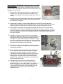
REOPUS H Ignition Installation
Instructions.
6/2014
The REOPUS H is a Hall Effect amplifier circuit board and Pickup designed to replace the
Lucas OPUS AB3 amplifier and Lucas OPUS pickup. A competent owner/technician can
install the amplifier and pickup himself.
The REOPUS H has been developed following of our experience with the REOPUS versions
3 and 4 which used the original Lucas OPUS pickup.
The REOPUS H Ignition provides ignition accuracy and stability to a level that was
unobtainable with the original Lucas OPUS system.
The REOPUS H amplifier is installed into the original Lucas OPUS AB3 alloy case and uses
the existing wiring, connectors, ballast block and coil type.
REOPUS H pickup replaces the original Lucas OPUS pickup and is installed in the
distributor as original and connects to the original amplifier 3 pin connector, and uses the
original timing rotor,
The REOPUS H “A Type “pickup is connected to the original pickup wiring inside the
distributor.
The REOPUS H Pickup. “B Type” (Black pickup wires) and “C Type” (Red, Yellow, Black,
Pickup wires) pickups are supplied complete with grommet to fit original V12 Jaguar
distributor and 3 pin connector. The REOPUS H ignition system is compatible with the rest of
the ignition components therefore you can maintain the ignition system as per the
manufacturer’s instruction manual. (Except the pickup test.) We have included 2 diagnostic
LED’s on the circuit board to indicate the power supply and pickup operation.
Please read the instructions completely and thoroughly before you start.
If you are not comfortable fitting it yourself, we strongly recommend you take your Lucas
OPUS amplifier case together with your REOPUS H amplifier and pickup and the instruction
sheets to a competent Auto electrician.
The REOPUS H amplifier must only be used with a REOPUS H pickup.
The REOPUS H amplifier must not be connected to an original Lucas OPUS pickup.
The REOPUS H pickup must not be connected to an OPUS or a REOPUS version 3 or 4
Amplifier unless the amplifier has been converted to a REOPUS 3H or REOPUS 4H.
The REOPUS H Kit includes:
• 1 x REOPUS H amplifier circuit board.
• 1 x REOPUS H pickup. Must be ordered with amplifier
First install the REOPUS H pickup Note illustration is for Jaguar V12
REOPUS H Type A, B, C pickup instructions are supplied with your
pickup.
Remove Distributor Cap
Remove Distributor Arm
Remove Distributor Timing disc
Remove 2 screws holding the pickup.
Remove the Lucas OPUS pickup from the distributor.
Now install your REOPUS H pickup back into your distributor.
Make sure the pickup wiring is clear of the Timing disc.
Refit the timing disc and set the pickup gap to between .015 and .025in.
Refit the Distributor rotor arm refit the Distributor cap.
!1
Next install the “REOPUS H” circuit board into your OPUS
amplifier casing.
Disconnect the pickup connector, the ballast resistor connector,
and the positive and negative wires from the coil and remove the
amplifier from the vehicle.
1) Remove the 4 base plate screws from the bottom of the
amplifier unit. The photos show an early OPUS. Later
versions have different colored boards and wiring. (See 10
below).
2) Carefully lever off the base plate, taking care not to damage
the paper gasket, which should be reused when fastening
the plate after installation.
3) Remove the 6 Posidrive screws holding down the Lucas OPUS circuit board and
carefully remove the board from the amplifier case. You will need to push the wires and
rubber grommet from the top of the case to provide enough wire length to do this.
4) Depending on the model of the amplifier, the board will have a flat 5 or 6 wire cable
attached to it. The 6th wire is a Blue/White Tachometer (also known as a Rev-counter)
wire. If not present, (5 wires) the Tachometer will be driven off the coil negative terminal
(via a 6.8KΩ resistor). There is no connection to Pad T on the REOPUS H board with
the 5 wire systems.
5) Carefully cut the wires as close to the circuit board as
possible, to ensure they will be long enough to solder to the
pads on the REOPUS H board. Some early boards are
covered in a creamy white rubberised material, so scrape
this off to reveal where the wires attach to the board. Keep
the colour coded sleeves or bands on the respective wires.
(See photos & illustration in step 8 below).
6) Cut the wire connecting the capacitor on the base plate
and the OPUS board. The REOPUS H board makes this
component redundant.
7) Fit the wires through the aluminium Heat sink/cable slot
of the REOPUS H circuit board making sure that the
components are facing towards you as in the photo.
Position the wires and rubber grommet in the top of the
case and later seal with a silicone sealant to prevent
water ingress, now position the circuit board into the
amplifier case. Using 4 of the original screws fasten the
circuit board into the case.
8) Carefully strip the ends of the wires and tin them.
Carefully solder the wires, into the soldier pads as
detailed on page 3, to the solder pads 1, 2, 3 and A, C, T
on the component side (as in photo) of the REOPUS
circuit board. Note the wires must be soldered on the
component shown and the other side if possible,
especially Pad C.
!2
Early Type (Black Wires with colored bands)
REOPUS H “B pickup”
Pad 1 = Black wire Red trace/Band
Pad 2 = Black Wire (No band)
Pad 3 = Black wire Yellow Band
Pad A (Batt +) = Red and Black Band
Pad C (Coil -) = Black and White Band
Pad T (Tachometer) = Blue and White Bands
Later Type Coloured wires (5 or 6)
REOPUS H “C type pickup”
Pad 1 = Red wire
Pad 2 = Black wire
Pad 3 = Yellow wire
Pad A (Batt +) = Red/Black wire
Pad C (Coil -) = Black/White wire
Pad T* (Tachometer) = Blue/White wire
*Note. The Blue/White Tachometer wire is not present in the 5 wire units. If your car has
been changed to a later 5-wire system we suggest you leave it this way as the ballast block
may also have been changed. To restore it to its original format can create rev counter
problems. Visit our website Ballast block section for more details.
9) Now tighten the 4 Posidrive screws holding the circuit board into the alloy case.
10) Next, reconnect the pickup module and the Ballast resistor to the amplifier. DO NOT
RECONNECT THE POSITIVE AND NEGATIVE COIL WIRES AT THIS STAGE.
11) Turn the amplifier over so that you can see the REOPUS H amplifier board and
connect the amplifier case to the engine so as to create the amplifier case negative
connection.
12) Turn the ignition switch to the run position (do not attempt to start the engine) the Red
LED on the circuit board should be ON. If not go to Page 4
13) Now turn over the engine on the starter motor. The Red LED will be ON and the Green
LED will flash (6 times per engine revolution) indicating the pickup circuit is OK. Turn
OFF the ignition switch.
14) If all is OK, refit the amplifier base plate using the original screws and paper gasket.
15) Refit the amplifier back in the original position.
16) Reconnect the coil wires positive (white Green) and negative (white/Black) wires and
ensure the pickup and the ballast resistor are connected to the amplifier.
A quick test to check for spark for your REOPUS H ignition installation. Remove the
coil HT lead from the center of the distributor cap insert a spark plug into the end of the HT
lead place the spark plug onto the engine to create the HT circuit turn the ignition ON if you
connect and disconnect the pickup at the 3 pin connector you should have a spark across
the plug gap. If all appears OK reconnect the Coil HT wire to your distributor and now it’s
time for your Road Test.
If no spark proceed to page 4.
!3
The REOPUS H Pickup and amplifier will not alter the existing ignition timing, however we
recommend the ignition timing be checked using an ignition stroboscope as detailed in the
service manual for ultimate performance and economy.
Fault finding for the REOPUS customer.
Your car is now about 40 yrs old and the wiring has possibly had little maintenance over the
years or has possibly been altered by a previous owner refer to the maintenance manual
wiring diagram.
If you do have problems we suggest you carry out the following tests with the REOPUS H
circuit board mounted in the Amplifier case with the connectors to the coil and the ballast
resistor in place and the Amplifier case connected to the engine (negative) with the circuit
board and LED’s visible.
On the REOPUS H circuit board are 2 LED’s for diagnostic purposes. The Red and Green
LED’s are referred to in the following test procedures.
Caution: When the coil circuit is disconnected a high voltage from the coil primary and
secondary discharging causes a high voltage for a few milliseconds, it can cause some
“discomfort”, we strongly advise switching OFF the ignition before connecting or removing
your amp-meter during the following tests. Before proceeding with any ignition circuit test we
suggest that you remove the coil HT lead from the center of the distributor cap insert a spark
plug into the end of the HT lead place the spark plug onto the engine to create the HT circuit
it is also a good visual test.
Note 2: The ignition should not be switched ON for long periods during the following tests as
the coil and the ballast block will get hot.
If the RED LED on the REOPUS circuit board is not illuminated
1. With the ignition switch ON the Battery voltage should be about 12.7 volts. (subject to
battery charge and condition)
2. You should have about 12V on pad A on the amplifier circuit board and the Red LED
should be ON provided the Ballast Block and wiring-connections are OK. If the RED
LED is not ON you may possibly have a short circuit in the amplifier or pickup wiring or a
High resistance connection on the Ballast block.
3. Check your solder connections on the circuit board.
A. Check for broken wires. We suggest if crimp lugs have been replaced at any stage
they should be soldered; crimp connections are not reliable. Note the original lugs
were spot welded.
B. Check the ballast block resistance, information is on www.reopusignition.com
C. Check connectors and terminals are clean.
D. When above tests are OK.
E. Now switch ON the ignition, if all is correct you should have +5volts on the coil +
terminal when ignition coil circuit is OK.
Note: The ballast resistor block and starter relay increases the coil voltage during
starting and lowers the coil volts in the run mode so as to prevent the coil from
overheating.
If the GREEN LED does not flash When the engine is cranked over and the RED LED is
ON. The Green Led should flash when a Ferrite rod on the distributor rotor passes the
center of the pickup.
The Green LED will also flash briefly when the 3 pin pickup /amplifier plug is connected or
disconnected.
With ignition switch ON and the Pickup connected to the REOPUS H circuit board with your
voltmeter connected across Pads 1 and 2 there should be 5 volts, if you do not have any
voltage disconnect pickup at the connector, if you now have 5 volts there is possibly a short
in the pickup circuit.
1. Check your wiring has not shorted to the amplifier case.
2. Check pickup wiring for damage.
3. Check the pickup for damage.
4. Clean pickup connector.
!4
If the there is no spark and the RED LED is on and the GREEN LED flashes when the
engine is cranked over.
If you have about 5V on the coil + terminal this would normally indicate the coil is drawing
current and the ballast block is OK. 5V is the correct coil voltage after the ballast Block when
in the run mode. In the start mode the coil voltage is increased by about 20%. The ballast
Block reduces the coil current when the ignition is in the run mode to prevent the coil from
overheating, in the start mode the Ballast block increases the coil voltage to provide an
increased spark to improve cold and hot starting . If there is an open circuit or a high
resistance connection in the coil circuit the Coil + terminal may be up to 12Volts this
indicates an open circuit and no coil current and therefore no spark.
The following procedure tests the, Ballast resistor and the coil circuit provided it is wired as
original.
1. Turn OFF ignition
2. Remove the coil HT lead from the centre of the distributor and connect to a spark
plug on the engine to create a HT circuit. This allows any coil High voltage to be
dissipated across the spark plug gap will you do these tests.
3. Remove the negative connector from the coil.
4. Connect an amp meter (10 amp DC range) between the coil negative terminal and the
engine.
5. With the ignition switched ON, you should have between 3 and 4 amps showing on
the meter.
6. Provided 5 above is OK this means the coil circuit is OK.
7. If no current check Coil and Ballast block Resistance and connections, visit our
website for Ballast block details.
8. Now connect your Meter + lead to the coil negative terminal and your meter Negative
lead to the coil negative/ amplifier wire you removed from the coil negative terminal.
9. Now with the ignition ON you should have about 3to 4 amps displayed on your meter.
If no current there is possibly a fault in the amplifier or output transistor. The transistor is
rated at 20amps and 600volts so this is unlikely unless it has been shorted. Contact
REOPUS for assistance we are happy to help.
Misfiring.
Check Pickup clearance to rotor. 0.020” ± 0.005
Are the Spark plugs clean? If the engine mixture is too rich the plugs will foul and
engine will be hard to start, especially when Hot.
Black spark plugs = rich mixture, Faulty Ignition leads, faulty Coil, or flooding
carburettors.
Misfiring under light acceleration (when engine is up to operating temperature) this can be
due to no oil in the carburettor dashpots or a lean mixture.
Check ignition timing and mechanical advance is OK.
Check Battery voltage, with the engine at approx 1500RPM the voltage at the Battery
terminals should increase to at least 13.8volts and preferably about 14.3volts. Low battery
volts can also be due to a faulty Alternator voltage regulator or alternator. Low volts = low
coil HT output.
Check carburettors are correctly balanced.
If your car starts to accelerate then dies the problem is possibly a Lean mixture, fuel
starvation.
A. Low fuel pressure. Rebuild fuel pumps.
B. Check pump efficiency
C. Blocked fuel pipes.
D. Check carburettor float levels.
If the misfiring happens after a short while, remove the petrol filler cap does it suck air? If it
does the fuel tank breather is possibly blocked.
Faulty ignition leads will cause misfiring under load. Open the car bonnet after dark with the
engine running you may observe sparks from the ignition leads, if so replace the leads.
REOPUS gives more spark energy compared with the old OPUS amplifier. I recommend
NGK; BP6ES spark plugs for carburettor V12 engines.
!5
Additional tips and checks
Make sure original wire connectors and terminals are clean and protected from corrosion.
HT leads and spark plugs should also be in good condition. Distributor cap must be dry and
clean inside and outside.
Whether your engine has carburettors or fuel injection, the fuel delivery system and the
ignition system are interdependent. Many faults can be “either/or” scenarios, so ensure the
fuelling system is also functioning at the correct pressure when the engine is running.
A very common is the centripetal advance weights in the base of the distributor being “stuck”
with dried up grease even rust. This will drastically affect the mechanical advance of the
ignition timing and they need to be cleaned, freed, and lubricated with a high temperature
lubricant.
The vacuum advance or retard module is another weak point. The internal rubber
diaphragm hardens with age and heat then splits or cracks. This will affect the idle speed
engine performance, temperature, and fuel economy.
All REOPUS circuit boards have been designed and manufactured using high specification
industrial quality components and manufactured to instrument standards.
The circuit board is not a modular unit and therefore repairable and can be upgraded to the
latest specs if required.
We look after our customers and our technical support is free via
email.
The original REOPUS 3 and 4 amplifiers can be modified to operate with the REOPUS H
pickup contact the factory for details.
REOPUS Warranty.
The manufacturer warrants, for a period of 5+ years from the date of purchase, that
the REOPUS H circuit board and Pickup is free from defects in material and
workmanship.
The manufacturer’s obligations under this warranty are limited to the REOPUS H
circuit board and Pickup only when it is used as a replacement for the Lucas Opus
Type AB3 ignition trigger amplifier together with the original car manufacturer’s
ballast resistor, REOPUS H pickup sensor and an appropriate coil.
All warranty claims will require examination at our manufacturing facility,
transportation charges pre-paid, and if after examination, the unit is found to be
defective we will either repair or replace it at our discretion.
The warranty shall not apply to any units which have been damaged by poor
installation methods, repaired or altered except by the manufacturer, or which have
been subjected to abuse/misuse.
REOPUS Engineering Ltd pride ourselves with our high level of
technical support. If you have any problems with your REOPUS,
please don’t hesitate to contact us for assistance.
Email: [email protected]
Web site; www.reopusignition.com
!6