1
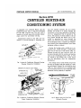
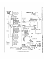
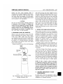
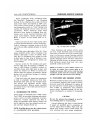
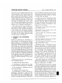
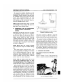
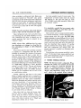
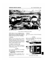
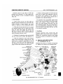
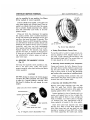
AIR CONDITIONING—429
CHRYSLER SERVICE MANUAL
Section XVII
CHRYSLER HEATER-AIR
CONDITIONING SYSTEM
CONTENTS
Page
Operating Controls
432
Air Discharge and Distributors
435
Temperature Control
435
Inspection and Testing of Complete Air Conditioning System
436
Compressor Capacity Test.
437
Precautions to Observe in Handling Refrigerant
438
Testing for Leaks with Leak Detector
439
Discharging the System
440
Evacuating and Sweeping System.
440
Moisture in Air Conditioning System
441
Charging the System
443
Testing Thermal Switch
444
Testing for Proper Super Heat
445
Pressure Relation Chart
446
Testing Electrical Switches and Control Circuits
447
Removal and Installation of Air Conditioning Unit
448
Removal and Installation of Expansion Valve.
450
Removal and Installation of Compressor
451
Service Diagnosis
455
DATA AND SPECIFICATIONS
COMPRESSOR
Location
Type
.........
Bore
Stroke
Displacement
Type Valve
Speed (Depends on axle ratio and tire size)
Oil Capacity (MOPAR Refrigerant Oil; 300 Saybolt)
Clutch
Muffler
.......
Airtemp
Right Cylinder
2 cyl.
2§f inch
l A inch
9.45 inch
Reed Type
Approx. 1250 r.p.m. at 25 m.p.h.
12 ounces
Rotating Coil
I n Compressor Discharge Line
6
l
CHRYSLER SERVICE MANUAL
430—AIR CONDITIONING
CONDENSER
Location
Front of Radiator
RECEIVER STRAINER-DRIER
Type
Location
Cylindrical Steel Container
Front of Front Radiator Yoke
REFRIGERANT
Refrigerant
Total Charge.
Freon 12 or Genetron 12
3 pounds
EVAPORATOR
Location
Cowl Panel
BLOWERS
Type
Location
Capacity
Centrifugal
I n Heater U n i t
250 to 300 cubic feet of air
per minute at high speed
Approximately 10 amps
Current Draw
SPECIAL TOOLS
Tool Number
C-3354
C-3355. .
C-3356
C-3444
C-3358
C-3361
C-3372
C-3128
C-3420
C-3421.
C-3363
C-3365
C-3366
C-3362
C-804
C-3478.
C-3429
C-744
C-3473
SP-2922
Tool Name
T E S T I N G OUTFIT—Consisting of one manifold complete w i t h two valves;
one 30 x 300 lbs. compound gauge; and one 600 lbs. pressure gauge. (Use
w i t h C-3365 and C-3366 Test Hoses.)
GOGGLES—Safety (Pair).
T H E R M O M E T E R S E T — T w o i n separate pocket cases. (Calibrated from
0° to 220° F.)
. T O R C H — L e a k Detector—Includes extra tank of liquid petroleum fluid.
W R E N C H — F l a r e Nut—Open E n d Box Type W and iy " (two per set).
W R E N C H — R a t c h e t Special Refrigeration Type—M" sq. Drive w i t h
sq.
and Y2 Hex. i n Handle.
. PUMP—Refrigeration Vacuum (Pump charged w i t h 75 Vis. Ref. O i l ) .
P L I E R S — D r i v e Pulley Seal Retainer Snap Ring.
A D A P T O R — F r e o n Cylinder Valve to Test Hose.
CLIP—Set of two—Attaching Thermometer to Tube.
W R E N C H SET—Flare Nut—Open E n d Box Type % " and 1" Openings (two
per set).
HOSE—Test w i t h End Plugs—4 Feet Long (set of two) (use w i t h C-3354).
HOSE—Test w i t h End Plugs—8 Feet Long (use w i t h C-3354).
. B E N D E R SET—For M", /fe", W, W, V2 and
Tubes.
. .TOOL—Tube Flaring.
CUTTER—Tube.
SCALE—Freon Weighing.
TEST LAMP.
S E A T P U L L E R and installing tool.
COMPRESSOR C A P A C I T Y T E S T V E N T CAP.
s
5
AIR CONDITIONING-^31
CHRYSLER SERVICE MANUAL
Section XVII
CHRYSLER HEATER-AIR
CONDITIONING SYSTEM
A completely new combined Heater and A i r
conditioning unit ( F i g . 1) has been developed
for the 1957 Chrysler cars. The new unit is
located i n the dash area and provides temperature control for all-weather driving.
Temperature control i n the 1957 A i r Conditioner is secured through a reheating pro-
OUTSIDE AIR COWL
VENT INTAKE
HEATING CORE
EVAPORATOR COIL
O N E - P I E C E MOLDED
PLASTIC HOUSING
WATER FLOW
CONTROL VALVE
BLOWER
COMPRESSOR
LINES
FROM E N G I N E
BLOCK
Fig. 1—Heater-Air Conditioning (Schematic Drawing
Passenger Compartment Installation)
DEFROSTER OR COOLING OUTLET GRILLES
OUTSIDE COWL
VENT INTAKE
EVAPORATOR COIL
cess. For summer operation, the air is dehumidified and cooled as i t passes through the
evaporator coil and then reheated by the heater
core to a temperature that is selected by the
driver. The amount of reheat added to the air
as i t passes through the heater core is controlled by metering hot water through the
heater core. The flow of hot water is regulated
by a modulating valve. A reheat type temperature control gives dehumidification even when
minimum cooling is desired.
During the heating cycle, outside air is i n troduced into system through a permanently
open vent i n the top of cowl section ( F i g . 2 ) .
Passing through the open fresh air door, air
is drawn through both the cooling and heating
coils by the Centrifugal Blower ( F i g . 3 ) . The
air, heated by the heating coil, is then forced
into the distribution duct for temperature
distribution.
The cooling cycle is quite similar except that
air may be brought from the outside or i t may
be recirculated through the recirculating door
(Fig. 4 ) . The controls are so arranged that
the recirculation feature is only employed when
maximum cooling capacity is required.
HEATER CORE
FRESH AIR DOOR
POWER PISTON
T4
COWL VENT
AIR CONDITIONING
\ HEATER SWITCH
CONTROL LEVER
PLENUM
BLOWER
V
CHAMBER
PANEL AND FLOOR DUCT
DISTRIBUTION DUCT \ DAMPER CONTROL \ ^ \ q 57x589
COOLING HEATING
- WARMER
COWL VENT DOOR OPEN
BLOWER
57x597
Fig. 2—Heater-Air Conditioning (Schematic Drawing
Fig. 3—Blower Motor a n d Vent Door
Engine Compartment Installation)
(Schematic Drawing)
-7
432—AIR CONDITIONING
CHRYSLER SERVICE MANUAL
COOLING HEATING
COOLING HEATING
COWL VENT DOOR (CLOSED)^
RECIRCULATING
DOOR (OPEN)
RECIRCULATING
DOOR (OPEN)
DAMPER DOOR
\
DAMPER
57x596
\
Fig. 4—Recirculating a n d Damper Door
57x591
Fig. 6—Recirculating a n d Fresh Air Door
1. OPERATING CONTROLS
The controls f o r the heater-air conditioner are
p a r t i a l l y power actuated.
The m a i n control lever, operating t h r o u g h
a cable, operates the water temperature valve
and also the fresh a i r and recirculating door
through t w o electric switches, the solenoid
valve, and power piston assembly ( F i g . 5 ) .
When the solenoid valve is energized, i t permits engine oil pressure to act on the power
piston, closing the cowl vent fresh air door
and opening the recirculating door. F i g u r e 6
shows fresh a i r and recirculating doors. F i g ure 7 shows schematic diagram hydraulic circuit for operating the power piston.
Figure 8 illustrates the dampers used i n cont r o l l i n g the system, and control components
that are mounted on the instrument panel.
AUXILIARY
TUBE
OIL
T W O WAY
DRAIN
F O R A I R AND
LEAKAGE
PAST
PISTON
SOLENOI
VALVE
CHECK
TO
X
VALVE A
PREVENT
LOSS
OF OIL
rFROM
PRESSURE
DURING E N G I N E
IDLE
OIL
CIRCUIT
CIRCUIT
^
POINT IN ENGINE
OIL
WHEN
WHEN
T O LOW P R E S S U R E
P O I N T IN E N G I N E
OIL
SYSTEM
SYSTEM
ACTUATION
( RECIRCULATING
OIL
HIGH
^PRESSURE
IS R E Q U I R E D
DOOR O P E N )
PRESSURE
( R E C I R C U L A T I N G DOOR
IS NOT R E Q U I R E D
CLOSED )
57 X 499
Fig. 7—Hydraulic Circuit for Power Piston
DAMPER UPPER
OR LOWER
LEVEL SELECTION
POWER
PISTON
DISTRIBUTION DUCT
-HIGH PRESSURE ENGINE OIL
Fig. 5—Power Piston a n d Recirculating Door
57x592
Fig. 8—Distributing Duct a n d Control Components
CHRYSLER SERVICE MANUAL
AIR CONDITIONING—433
The fresh air door and the recirculating
door are linked together i n such a manner that
when one is closed the other is open.
1. Compressor clutch and water valve
heating element w i l l be energized
(Figs. 9 and 10).
The two air flow control dials are mounted
on concentric shafts. The inner "Blower"
switch controls the speed of the blower motor.
Three speeds are available through the selection of wire taps i n the motor fields.
2. Hot water shut off to heater core.
The outer dial marked " A i r " controls the
positioning of distribution duct damper, and is
used to proportion the air distribution between
the instrument panel grilles and the distributor
duct slots. The control is lettered " U p " and
"Down" w i t h arrows indicating the proper
rotation for panel or floor discharge.
4. Maximum cooling w i l l be obtained.
The toggle switch w i t h positions marked
"Cooling" and "Heating" permits the energizing of the compressr clutch circuit and the resistance coil of the water temperature control
valve. This action occurs when the switch is
placed in the "Cooling" position. I n the "Heating" position, i t insures that these circuits w i l l
not be energized. I t should be noted that the
main control lever must be i n some position
other than "Off" to permit the closing of the
clutch and coil circuits by the toggle switch.
The position of the toggle switch also has a
bearing on the fresh air door and recirculating
door.
2. POSITIONING CONTIOL LEVER
a . Moving the main control lever from "Off"
to "Cold" (No. 2) position, w i t h the toggle
switch i n "Cooling" position, the following sequence of operation w i l l result:
DISCHARGE
SUCTION
NE COMPRESSOR \
L,
L , N E
TO TEMPERATURE
CONTROL SWITCH
THERMAL
SWITCH
3. Fresh air door closed and recirculating
door open resulting i n 80% recirculation air, 20% fresh air.
h. Moving the main control lever to the right
from the "Cold" or No. 3 position w i t h toggle
switch on "Cooling" position, the following
operational sequence w i l l occur:
1. T | i ^ | r e s h air door opens and recirculat i n g door closes de-energizing the solenoid valve.
2. Full fresh air cooling obtained.
3. Lever mechanism picks up the cable
controlling the water temperature control valve and prepares to open the
valve.
4. Hot water shut off to heater core.
c. Moving the main control lever from No.
3 position through "Warmer" to No. 4 position
opens the water temperature control valve. A t
the warmest point i n the "Cooling" position,
the water valve w i l l allow the heater core to
reheat the cooled air to approximately 75° F.
d. Moving the main control lever from "Off"
to "Cold" or No. 2 position, ( F i g . 6) w i t h toggle switch i n "Heating" position.
1. De-energizes the solenoid valve, allowing the recirculating door to close and
the fresh air door to open.
2. Hot water shut off to heater core.
3. Total fresh air ventilation obtainable,
proportioned as desired through i n strument panel grilles and distributor
duct slots.
e. As the main control lever is moved from
the "Cold, No. 2 position to No. 3 position, w i t h
the toggle switch i n "Heating" position:
RECEIVER-STRAINER-DRIER
LIQUID EXPANSION
LINE
VALVE
Fig. 9—Heater Air Conditioning
(Schematic of Components)
57x593
1. Lever mechanism picks up the cable
controlling the water temperature control valve and prepares to open valve.
2. Hot water shut off to heater core.
3. Total fresh air ventilation is obtainable.
CONTROL ACTIONS
WITH ENGINE
OPERATING
FRESH AIR DOOR CLOSED
RECIRCULATING DOOR OPEN
N O . 1 SWITCH OPEN
N O . 2 SWITCH CLOSED
COMPRSSOR CLUTCH-
-18 BLUE-
r
THERMAL SWITCH
FRESH AIR DOOR O P E N N O . 1 SWITCH CLOSED
HEATING
RECIRCULATING DOOR C L O S E D N O . 2 SWITCH CLOSED
FRESH AIR DOOR O P E N N O . 1 SWITCH CLOSED
RECIRCULATING DOOR CLOSEDN O . 2 SWITCH OPEN
OFF
COLD
COOLING
sm HEAT
WARMER
.—•
COOL'
HE
CLUTCH CIRCUIT CLOSED
FOOLER CIRCUIT CLOSED
FRESH AIR DOOR OPEN
RECIRCULATING DOOR CLOSED
N O . 1 SWITCH CLOSED
N O . 2 SWITCH OPEN
CLUTCH CIRCUIT CLOSED
FOOLER CIRCUIT CLOSED
FRESH AIR DOOR CLOSED
RECIRCULATING DOOR OPEN
N O . 1 SWITCH CLOSED
N O . 2 SWITCH CLOSED
® INDICATES
POSITION O F
MAIN LEVER
ARM
CLUTCH CIRCUIT OPEN
FOOLER CIRCUIT OPEN
FRESH AIR DOOR CLOSED
RECIRCULATING DOOR OPEN
N O . 1 SWITCH OPEN
N O . 2 SWITCH CLOSED
CAR C O O L I N G AND HEATER
BLOWER M O T O R -
" F O O L E R " ELEMENT
WATER VALVE
RHEOSTAT
/
l A
r
V
MG ~
(RESISTANCE DECREASES A S
WATER VALVE IS OPENED)
-18 WHITE-
-CZ3—18 WHITE—^)
18 RED
SWITCH N O . 1
SWITCH N O . 2
NORMALLY
NORMALLY
CLOSED
OPEN
FRESH AIR AND
18
RECIRCULATING
RED
DOOR SOLENOID
(ENERGIZING O F
SOLENOID CIRCUIT
CLOSES FRESH AIR
AND OPENS
RECIRCULATING
DOOR)
COOL
NORMALLY
OPEN
NORMALLY CLOSED
0
18 YELLOW
-18 WHITE-
HEAT
-SELECTOR SWITCH
CAR C O O L I N G
BLOWER SWITCH
16 DARK G R E E N WHITE STRIPEv
\
•—18 RED
TEMPERATURE
GAUGE
IGNITION SWITCH
BATTERY
HIGH,
16 TAN-WHITE STRIPE
16 BLACK-WHITE STRIPE
16 BROWN-WHITE STRIPE-
Fig. 10—Wiring Diagram (Heater-Air Conditioning)
16 BLACK
57x508
CHBYSLE1 SEH¥ICE MANUAL
AIR CONDITIONING—435
ALIGNMENT ARROW5
57x594
Fig. 11—Defroster Duct (Schematic Drawing)
f. Moving the main control lever from No.
3 position through "Warmer" to No. 4 position
opens the water temperature control valve. A t
the warmest point i n the "Heating" position,
the water valve allows the temperature of the
discharge air to reach approximately 130° F.
The fresh air door w i l l always open and the
recirculating door w i l l always close when car
engine is stopped. This puts the system i n a
"safe" position for car washing, parking during a rainstorm, etc.
3. A l l DISCHARGE AND DISTRIBUTION
Cooled or heated air can be distributed to either
upper or lower level of car and i t can be proportioned between the upper and lower level.
Fig. 13—Discharge Grille
Conditioned air is forced into the car by the
blower that is mounted to dash. The air enters
a distribution duct and can either be discharged
toward the floor of car through slots in the
distribution duct or i t can be forced up to two
discharge grilles i n the top of instrument panel
by means of a damper. I n general, the air w i l l
be discharged to the lower level for heating
and through upper grilles for defrosting (Figs.
11 and 12) and air conditioning.
The discharge grilles i n the top of the i n strument panel ( F i g . 13) can be rotated
through a full circle. The grilles, also have
hinged deflectors which can be used to direct
air up along the roof or directly at the occupants of the front seat.
4. TEMPERATURE CONTROL
UPPER DISTRIBUTION DUCTS
ACTUATOR RETURN
57x624
WINDSHIELD WIPfcRl
MO (OR
For summer operation, the air w i l l be dehumidified and cooled as i t passes through the
1LINKI
HEATER CORE
THERMAL
SWITCH
•IBi
. £...
.FRESH AIR DOOR- ; t vS ACTUATOR •
;
•1
/
WATER FLOW VAlVEi
P-^LOWFR^DISTRIBUTION DUCT
\\
Fig. 12—Distributor Duct Installed
57x623
EXPANSION VALVE V ^ ^ ^ N ^ ^
Fig. 14—Thermal Switch Installed
^SK**.-^
436—AIR CONDITIONING
CHRYSLER SERVICE MANUAL
the secondary tube, i n effect, " t r i c k s " the p r i m a r y capillary tube, ( F i g . 15) located i n the
d i s t r i b u t i o n duct, by m a k i n g i t appear w a r m e r
than the discharge a i r flowing over i t . The
valve w i l l then tend to close, thus reheating
the a i r less and s h i f t i n g the temperature to
the desired cooler level.
5. INSPECTION AND TESTING O F COMPLETE
AIR CONDITIONING SYSTEM
a. Preparation for Tests
Move car into a well ventilated area and shut
off engine. Connect exhaust suction system to
t a i l pipe. Inspect condenser and radiator for
bugs, etc., and blow out f r o m side opposite entrance w i t h compressed air.
Fig.
15—Capillary Tube a n d W a t e r
Valve
evaporator coil and then reheated by the heater
core to a temperature that is selected by the
operator. The amount of reheat added to the
air as i t passes t h r o u g h the heater core is controlled by metering hot water t h r o u g h the heater core. The flow of hot water is regulated by
a modulating valve. A reheat type temperature
control gives dehumidification even when m i n i m u m cooling is desired.
A thermostatic switch is used to prevent
evaporator coil f r o m frosting over. The t h e r m a l
switch is installed i n the evaporator to sense
the fin temperature of the coil. As temperature
of evaporator fins decreases to a point where
frost-over m i g h t occur, the t h e r m a l switch
( F i g . 14) w i l l break the compressor clutch circuit, stopping r e f r i g e r a t i o n u n t i l fin temperature increases to a point .above the freezing
point of water.
The same modulating water valve is used
for temperature control for both heating and
cooling. The temperature range of the valve is
changed by an electric resistance heating coil
when cooling is selected by operator. The valve
is designed to control the discharge a i r temperature. For the heating cycle this temperature range w i l l be f r o m about 75 to 130° F . The
discharge range f o r the A i r Conditioning or
summer operation w i l l be approximately 40 to
75° F . This shift i n temperature range is accomplished by the heating of the valve's temperature sensitive secondary capillary tube
w i t h resistance heating coil which is wound
around the secondary capillary tube. H e a t i n g
b. Radiator
Check radiator pressure cap. A 14 pound pressure cap and a 180° F . thermostat is used i n
all models. Check cooling system and add water or anti-freeze to m a i n t a i n proper level. The
cooling system should be protected to a temperature of 20° above zero f o r summer (lower
for w i n t e r ) .
c. Compressor Belt
Check compressor belt tension w i t h a 5 pound
pull scale i n center of longest belt span. Compressor belt deflection (each belt) should be
Yu\ inch deflection f o r new belt and % inch
for used belts.
N O T E : A belt having a minimum of *4 hour
engine run is considered a used belt.
CAUTION
Always replace both belts. Never run a new belt
with an old belt. Check compressor brackets
and bracket attaching bolts for being tight.
d. Blower Motor
Check f o r loose or poor electrical connections.
Check blower switch. Make a blower circulation
check by operating the blower on each of its
three operating positions: " L o w " , " M e d i u m "
and " H i g h " . Check f o r change i n operational
speeds, and circulation.
e. Drains
Check plenum chamber and a i r conditioner
housing drains ( F i g . 16) for being clear.
CHRYSLER SERVICE MANUAL
HEATER BLOWER OPENING
\
HEATER CORE TO DASH GASKET
\
\
HEATER RECIRCULATING DOOR
AIR CONDITIONING—437
zero, and from a zero reading to a vacuum
reading "pumping down" all of the refrigerant
out of compressor. W i t h compound gauge reading 20 to 25 inches of vacuum, rotate valve
stem of discharge service valve (clockwise)
until valve is completely front-seated. Open
right hand shut-off valve (counter-clockwise)
on the gauge manifold set.
NOTE: This will allow the small amount of
gas trapped between compressor and discharge
valve to vent down to zero reading through
gauge manifold set center connection hose.
Fig.
16—Plenum Chamber and Drain Openings
6. COMPRESSOR CAPACITY TEST
To make a compressor capacity test, the system
must be isolated from the compressor. I n isolating the compressor from the system, a .020"
test cap, Tool SP-2022 must be used to measure
the amount of air pressure compressor delivers
at given engine speed.
To make a compressor capacity test w i t h a
test cap, proceed as follows: Start engine, operate at 1200 r.p.m. T u r n blower switch to
" H i g h " and temperature control lever to "Cold"
position. Open car windows. Allow engine to
operate until engine and compressor are up to
normal operating temperature. Stop engine and
remove the valve stem protective caps from
suction and discharge valves. Use ratchet
wrench, Tool C-3361 and back-seat both suction and discharge service valves by turning
valves (counter-clockwise) all the way.
Remove service port caps from suction discharge service valve and attach hoses from
gauge set manifold Tool C-3354 ( F i g . 17). A t tach hose from compound gauge on left of
gauge assembly to the suction service port. A t tach hose from right gauge to discharge service
port. Close both right and left hand shut-off
valves (clockwise) on gauge set manifold.
Start engine and w i t h compressor operating,
adjust engine speed to exactly 500 r.p.m. W i t h
ratchet wrench, Tool C-3361 rotate valve stem
of suction service valve (clockwise) until valve
is completely front seated. Front seating the
valves w i l l cause suction pressure to drop to
Open left hand shut-off valve on manifold,
remove hose from center connection of gauge
set. Attach capacity test cap, Tool SP-2922, to
center connection of gauge set manifold. Disconnect manifold hose from suction service
valve leaving service port open.
CAUTION
Test cap must be absolutely clean before i n stallation on gauge set connection. Wash with
solvent and blow dry. Test cap is meter drilled
and wire or similar instrument should never
he used to open the vented orifice. I f this is
done a doubtful gauge reading may result.
Close left hand shut-off valve on manifold
while noticing the pressure rise reading on high
pressure gauge.
Operating engine at exactly 500 r.p.m. the
pressure reading on high gauge should read 190
to 210 psi. To make sure reading on gauge is
correct, open and close the left hand shut-off
valve on gauge set several times. I f pressure
readings rise on gauge and correspond to specified specifications, the compressor is functioning up to specifications.
Fig.
1 7 - G a u g e Set Installed (Tool C-3354)
438—AIR CONDITIONING
N O T E : I f pressure reading is below specifications and tachometer and gauge is reading accurately, stop engine and check the compressor
o i l level since low o i l level w i l l cause a lower
capacity test reading.
A d d o i l to compressor i f necessary and recheck the compressor f o r capacity test readings.
I f compressor pressure is below the prescribed
specifications w i t h o i l level at 2 inches at dip
stick, the compressor valve plate assembly on
both banks of compressor should be replaced.
A f t e r replacing valve plates on compressor,
make a capacity test to again determine compressor pressure capacity. I f compressor w i t h
oil level is corrected, and valve plates replaced,
does not come up to specified pressure, remove
suction service valve f r o m compressor. Inspect
suction screen (located i n opening under valve)
and see t h a t i t is clean, and gasket properly
seated. I f screen is clean, gasket not damaged,
and compression test does not come up to specifications, the compressor should be replaced.
CHRYSLER SERVICE MANUAL
Probe the gauge center connection w i t h t i p
of finger. I f p r o b i n g w i t h finger at connection
indicates no more gas is flowing, close r i g h t
hand valve on manifold gauge set. Stop engine
and t u r n both suction and discharge service
valves (counter-clockwise) u n t i l they are completely back-seated. A f t e r back-seating each
valve, t u r n each valve one t u r n (clockwise)
to be i n operating test position.
A f t e r completion of test, t u r n both suction
and discharge service valves (counter-clockwise) u n t i l they are f u l l y back-seated. Open
both hand shut-off valves on manifold to release pressure on manifold gauge hoses. Disconnect and remove hoses f r o m both service
valves. Replace valve stem and service p o r t
caps and both service valves. A d j u s t f a n belt.
Check both cylinder head to compressor attaching bolts f o r tightness.
7. PRECAUTIONS TO OBSERVE I N
HANDLING REFRIGERANT
WARNING
N O T E : W h e n replacing compressor, an adjustment must be made to compensate for the
o i l remaining i n system. Check and correct o i l
level i n compressor to 2 inches (dipstick measu r e m e n t ) . Start engine and r u n f o r approximately 15 minutes and check o i l level again.
Add or subtract to maintain specified l i m i t .
Remove compressor test vent cap f r o m manifold and w r a p cap i n clean cloth to protect
orifice f r o m d i r t and g r i t . Open r i g h t hand
shut-off valve on manifold gauge set. Close left
hand shut-off valve. Connect suction hose to
service p o r t of suction service port.
W i t h engine r u n n i n g at 500 r.p.m. and compressor engaged, "pump d o w n " the compressor
by bleeding the a i r out of compressor t h r o u g h
manifold gauge center connection. When 25 to
28 reading is indicated on vacuum gauge, t u r n
suction service valve a fraction of a t u r n
(counter-clockwise) f o r a few seconds and then
f r o n t seat the valve. This w i l l allow small
amount of gas accumulated i n suction line to
flow into compressor and crankcase, m i x i n g
w i t h and to be absorbed by the o i l .
N O T E : This operation w i l l also cause the gas
to flow t h r o u g h the compressor's cylinder and
out t h r o u g h the manifold gauge center connection.
Safety Goggles, C-3355, should be w o r n
protect the eyes.
to
When properly used, r e f r i g e r a n t is harmless.
A few simple precautions, however, should be
observed to guard against injuries or sickness
t h a t m i g h t occur when r e f r i g e r a n t is improperly handled.
a. Precaution
Do not expose eyes to liquid. Do not r u b eyes
i f splash of r e f r i g e r a n t hits them. A p p l y cold
water immediately to area of eye to gradually
raise the temperature above freezing point.
The use of antiseptic o i l is helpful since o i l
forms a protective film over eye ball u n t i l medical aid can be obtained.
b. Precaution
Do not discharge r e f r i g e r a n t i n area where an
open flame is present. The r e f r i g e r a n t n o r m a l l y
is non-poisonous. A concentration of gas i n a
live flame, however, w i l l produce a poisonous
gas. Splashing r e f r i g e r a n t on b r i g h t metal or
chrome should also be avoided because gas w i l l
t a r n i s h b r i g h t metal,
c. Precaution
Do not leave charging tanks uncapped. A l w a y s
CHRYSLER SERVICE MANUAL
replace cap after using charging tanks. A
charging tank is shipped equipped w i t h a heavy,
protective cap which is used to protect valve
and safety plug from damage. To avoid moisture getting into system, charging tanks should
not be opened to the atmosphere.
CAUTION
Use care to avoid moisture entering system. I t
is imperative when sweeping or charging the
system that the refrigerant be passed through
a Drier and Dry-Eye Assembly before the refrigerant enters the A i r Conditioning System.
See Figure 18 for methods of attaching "DryEye ' and " D r i e r " to tank assembly.
9
8. INSTALLING GAUGE SET MANIFOLD
Remove valve stem protective caps from compressor discharge and suction service valves.
Using Tool C-3361, make sure both valves
are completely back-seated (counter-clockwise).
The normal operating position is when valve
is rotated i n a (counter-clockwise) direction.
This position also isolates service valve ports
from system pressure.
Remove protective caps from both discharge
AIR CONDITIONING—439
and suction service port caps. Install four-foot
test hose from 600 pound gauge fitting on Tool
C-3354 to discharge service valve port fitting.
Install the other four-foot test hose from 300
pound compound gauge fitting on Tool C-3354
to suction service valve port fitting. Turn both
valve handles of gauge set, Tool C-3354 (clockwise) as far as they w i l l go. This w i l l completely seat valves and isolate gauge set manifold center outlet from test hoses. To admit
pressure gauges, rotate valve stems of both
suction and discharge service valves one turn,
(clock-wise).
8. TESTING FOR LEAKS WITH DETECTOR
When system is found to be low i n refrigerant,
or following repairs on system that necessitated
opening of connection, i t is necessary to test
for leaks and tighten connections, or to make
repairs as required before system is charged
and put i n operation. I f system has been discharged for making repairs or to eliminate
moisture, system must be evacuated before
partially charging to test for a leak.
Partially charge system w i t h refrigerant, as
outlined i n Paragraph 10, and proceed as follows : (This is necessary only where supply i n
system is very low, or when system has been
evacuated).
The Tool C-3444 (Test Torch) uses petroleum gas and does not require generating to
light. Just t u r n valve on, light i t , and adjust
to small flame. Move leak detector sniffer tube
over all connections. When leak is found, flame
in burner w i l l t u r n bright green. Move detector
tube around connection to determine magnitude
of leak. I f larger leak is found, color of flame
w i l l t u r n from bright green to bright purple,
NOTE; I f leak is found at flared connection,
try tightening connection, using two wrenches.
I f leak cannot be eliminated by tightening, system must be discharged, connection or flare reseated or replaced, system evacuated and again
partially charged, and re-tested. I f no leaks are
found, add to partial charge until system contains three pounds.
10. CHECKING REFRIGERANT BY SIGHT
GLASS METHOD
Fig. 18—Refrigerant Tank, Detecting Eye, Drier
Cartridge (Schematic View)
I n some cases, i t may be necessary to add refrigerant to system to provide cooling without
weighing, as is normally required.
440—AIR CONDITIONING
C H E Y S L E f l SEH¥ICE -MANUAL
Follow p r e l i m i n a r y steps, " I n s t a l l i n g Gauge
Set M a n i f o l d " , Paragraph 8, and C h a r g i n g
System 16, but eliminate those steps i n v o l v i n g
scale. S t a r t engine and operate at 1200 r.p.m.
T u r n blower control switch to " H i g h " position
and temperature switch to "Cold". Rotate both
suction and discharge service valves one t u r n
(clockwise). Where discharge gauge hand
fluctuates when engine is r u n n i n g , close discharge valve slowly (counter-clockwise) u n t i l
gauge hand steadies. Charge t h r o u g h drier.
Refer to F i g u r e 17 and install d r i e r as i n dicated.
Open tank valve one t u r n . Open suction valve
on gauge manifold slightly (counter-clockwise).
Control r e f r i g e r a n t entering system w i t h this
valve. Do not allow suction pressure to exceed
60 psi.
Carefully watch sight glass, ( F i g . 1 9 ) . Close
gauge manifold suction valve (clockwise) the
moment sight glass is clear of bubbles. Stopp i n g flow of refrigerant into system as soon
as sight glass is clear (free of bubbles) is i m portant. Too much refrigerant i n system can
cause damage.
Operate system f o r five minutes and again
observe sight glass f o r presence of bubbles. I f
there is still evidence of bubbles, continue to
carefully charge u n t i l sight glass is clear, and
repeat five minute r u n . Where no bubbles are
present after five minutes of operation, charge
system w i t h an additional charge of refrigerant f o r 10 seconds.
Close tank valve and loosen hose connection
at tank to gradually release gas f r o m hose.
Disconnect hose after gas has escaped. Backseat suction and discharge service valves
(counter-clockwise). Remove gauge manifold
and install service valve stem and service p o r t
protective caps.
11. DISCHARGING THE SYSTEM
Install gauge set manifold Tool C-3354. U s i n g
Tool C-3361, be sure both discharge and suction
service valves are fully backseated (counterclockwise). Connect eight-foot test hose to
gauge set manifold center fitting. Insert free
end of eight-foot hose into exhaust suction system and t u r n exhaust blower on.
N O T E : Expelling the gas into the exhaust system
is a recommended safety precaution.
Y
Fig.
SIGHT
CJIA'JS
19—Sight G l a s s Installed
Open discharge and suction service valves
one t u r n . Crack manifold gauge set discharge
hand valve a fraction of a t u r n (counter-clockwise) to allow gas to escape. Opening manifold
discharge hand valve too much i n order to more
quickly discharge system w i l l d r a w compressor
lubricant off w i t h the gas. As pressure on manifold discharge gauge drops near zero, open
manifold suction hand valve.
N O T E : If brazing or some similar repair is to
be made on system, leave system open to atmospheric pressure. After service work has been
completed, system must be evacuated, partially
charged, and leak tested before final charge.
12. EVACUATING AND SWEEPING SYSTEM
Whenever system has been open to atmosphere,
i t is absolutely essential t h a t system be evacuated and swept w i t h r e f r i g e r a n t to remove all
air and moisture. Connect gauge set manifold,
Tool C-3354, to compressor and condenser
service valves. Discharge system ( i f not previously discharged), as outlined i n Paragraph
11.
CAUTION
Be sure the pressure has dropped to zero before attaching hose to vacuum pump.
Connect eight-foot test hose to center fitting
of gauge set manifold and to connection on
vacuum pump (Tool C-3372). Open both discharge and suction service valves about one
t u r n , r o t a t i n g both valve stems (clockwise).
CHRYSLER SERVICE MANUAL
Open both gauge set manifold hand valves t u r n
(counter-clockwise). Start vacuum pump and
observe compound gauge. Operate pump until
gauge registers 26 to 28 inches of vacuum.
Continue evacuating at 26 to 28 inches for five
minutes. Failure to obtain 26 to 28 inches of
vacuum would indicate a leak i n system. Close
both gauge set manifold hand valves (clockwise). Turn off vacuum pump and remove long
test hose from pump. Charge system w i t h refrigerant gas, as outlined i n Paragraph 16.
Start engine and adjust speed to 1200 r.p.m.
T u r n blower control to " H i g h " and temperature control to "Cold". Operate in this manner
for five minutes and test for leaks. Discharge
system to sweep out any remaining moisture,
and again evacuate system at 26 to 28 inches
of vacuum for 10 minutes. Recharge system
w i t h three pounds of refrigerant.
13. MOISTURE IN AIR CONDITIONING
SYSTEM
Moisture i n automotive air conditioning systems is directly or indirectly the real cause of
many failures i n air conditioning systems.
Basically, moisture can be classified as visible
and invisible. Visible moisture, such as rain,
clouds, steam, etc., can be seen. Invisible moisture is water vapor which cannot be seen w i t h
the eye. This water vapor is everywhere—it is
in all solids, liquids and gases. I t is i n the air,
and the varying amount is expressed i n terms
of relative humidity. Withdrawal of refrigerant
from a system that is experiencing freeze-ups
at the expansion valve, does not ordinarily reveal visible liquid water i n refrigerant, yet i t
is there i n quantities sufficiently to stop refrigeration.
Moisture may enter the air conditioning system i n following manner:
a. System left open during repair.
b. Condensation i n tubing, leaky seal caps,
wet driers, unsealed charging hose or manifolds.
c. Use of wet oil or refrigerant from i m proper field handling.
d. Charging system without drier.
The measurement of moisture content i n a
refrigerant is expressed i n "Parts Per M i l lion" ( P P M ) . This can be illustrated by saying that one drop of water, i n one million drops
of water is one part per million. I t can also be
AIR CONDITIONING—441
further illustrated by stating that one drop of
water raises the moisture content of 25 pounds
of "Refrigerant 12" about 5 ( P P M ) , or 1 pound
of "R-12" about 125 ( P P M ) .
I n order to be certain the moisture content
of a "Refrigerant 12" A i r Conditioning is kept
out of the freeze-up range, acid producing and
corrosion range, the moisture content should
not exceed 10 ( P P M ) . The progressive result
of moisture i n excess of 10 (PPM) in "Refrigerant 12" is as follows:
Refrigerant 12 plus moisture equals freezeups at expansion valve.
Refrigerant 12 plus moisture equals acid
(Hydrochloric & Hydrofluoric).
Acid plus metals and refrigerant oil equals
corrosive sludge.
Corrosive sludge plus expansion valves equals
sticky or stuck valves.
Corrosive sludge plus screens and strainers
equal plugged screens and strainers.
Corrosive sludge plus compressor reed valves
equals corroded leaky valves.
Refrigerants such as Refrigerant 12 are
known as auto-driers. I n a closed container,
moisture tends to leave the liquid and concentrate i n the vapor. A full tank of "Refrigerant
12" when received from manufacturer, is as
"dry" of moisture as the manufacturer can
produce i t . Yet i t w i l l still contain from 6 to
10 (PPM) moisture i n the liquid phase. A t
room temperature, "Refrigerant 12" i n the
vapor phase (refrigerant gas above the liquid
in a tank) can hold as much as seven times
amount of moisture as i t does i n liquid phase.
This means starting w i t h a
frigerant 12" containing 6 to
ture i n the liquid phase, the
liquid can contain 42 to 70
full tank of "Re10 (PPM) moisvapor above the
(PPM).
As this vapor leaves the tank and is charged
into the A i r Conditioning System, the moisture
enters the system w i t h the vapor. As more and
more refrigerant vapor leaves the tank, more
and more liquid refrigerant boils into a vapor
and the vapor can extract a 7 to 1 ratio of
moisture from the liquid remaining i n the tank.
By the time the full tank of "Refrigerant 12"
is down to about half full, the remaining half
tank of refrigerant liquid and vapor w i l l be
very dry, as all of the moisture originally con-
442—AIR CONDITIONING
CHRYSLER SERVICE MANUAL
tained i n the f u l l tank of liquid has been extracted by vapor and charged into the A i r
Conditioning System.
CAUTION
Always
opened
anyone
of the
water.
insist o n delivery o f refrigerant i n untanks. Do not accept tanks refilled by
other than the manufacturer, because
possibility of the tank containing free
For the above reasons i t becomes imperative
when charging a system, to pass the r e f r i g e r ant vapor t h r o u g h an efficient d r i e r before i t
enters the system. I f this precaution is not
taken, as much moisture may be induced back
into the system as was removed d u r i n g evacuation and sweeping.
See F i g u r e 18 f o r method of attaching
" D r i e r " and " D r y - E y e " to t a n k assembly. Refer to " C h a r g i n g The System, Paragraph 16,
for use of " D r i e r " and ' D r y - E y e " equipment
to eliminate moisture f r o m system.
N O T E : D r i e r cartridges are available i n 8, 12,
20 and 30 cubic inches. A 12 cubic i n c h cartridge is recommended f o r use w i t h refrigerant
tank. O n receival, make sure cartridge is sealed
w i t h white plastic seal cap. This cap is used to
seal moisture f r o m d r i e r cartridge.
Used drier cartridges can be re-activated
when saturated w i t h moisture provided r e f r i g erant containing oil has not flowed t h r o u g h
the drier, by unsealing the cartridge and placi n g i t i n a heated oven f o r a given number of
hours. F o r example, i f the cartridge is placed
i n a 300 degree oven, i t should remain there
f o r 2 hours, 1 % hours i n a 400 degree oven,
or 1 hour i n a 500 degree oven, etc. A f t e r heati n g , allow cartridge to cool, reseal w i t h plastic
cap and gasket, store i n a d r y area ( a t room
temperature). To charge system refer to Paragraph 16.
14. CHECKING SYSTEM FOR MOISTURE
W i t h t u b i n g coil, sight glass, moisture detecti n g eye and cap made up i n t o an assembly,
as shown i n F i g u r e 20, remove valve stem caps
f r o m suction and discharge service valves,
back-seat and f u l l y open (counter-clockwise)
both valves. Remove caps f r o m valve service
ports and attach t u b i n g and flare fitting assembly to the valve service ports, as shown i n
F i g u r e 20.
S U C T I O N S E R V I C E VALVE
ON C O M P R E S S O R
DISCHARGE S E R V I C E VALVE
AT CONDENSER
r ^o w - "- M O I S T U R E
V
/
W ~
Yf
DETECTING
E Y E CAPPED
WITHOUT DRIER
CARTRIDGE
- SIGHT
GLASS
-CONTAINER WITH
COLD WATER
5 7 X 501
Fig. 20—Moisture Detecting
(Schematic Drawing)
Eye
F i l l the container w i t h cold water t o allow
for submersion of coil i n water, as shown i n
F i g u r e 20. T u r n valve stem of discharge service valve t w o t u r n s (clockwise). Purge a i r
f r o m t u b i n g by slowly loosening up the t u b i n g
n u t at suction service valve. A f t e r a l l the a i r
has been bled f r o m t u b i n g , retighten nut. Test
all connections f o r leaks. S t a r t engine and adj u s t engine speed to 1200 r.p.m. Open car w i n dows and move the operating lever to " C o l d "
position, and blower switch to " H i g h " .
Slowly turn, the valve stem o f the suction
service valve (clockwise) t w o f u l l turns, and
check sight glass ( F i g . 1 9 ) , f o r flow of ref r i g e r a n t liquid t h r o u g h glass. A f t e r approximately 15 to 20 minutes of engine operation
w i t h liquid flowing t h r o u g h the moisture detecting eye and i f the dot o f eye shows p i n k ,
excessive moisture is present i n system.
I f system is " d r y " or contains a m i n i m u m
of moisture, the dot o f eye w i l l slowly change
to light blue i n d i c a t i n g the system contains 10
to 20 ( P P M ) of moisture. W h e n d r y eye shows
a dark blue the same color as corresponds to
the dot on eye, i t is indicative t h a t system contains less t h a n 10 ( P P M ) of moisture and is
now ready f o r safe, satisfactory operation.
N O T E : I f moisture detecting eye shows p i n k ,
excessive moisture is present. L i g h t blue w i l l
indicate the system is border line, and moisture
content should be lowered.
AIR CONDITIONING—443
CHRYSLER SERVICE MANUAL
To remove the moisture detecting eye and
tubing assembly, proceed as follows: W i t h air
conditioning system operating, back-seat first
the discharge service valve, and then suction
service valve (counter-clockwise) and stop
engine. Remove tubing coil, sight glass, moisture detecting eye and cap assembly from suction and discharge service valves.
V
SUCTION S E R V I C E VALVE
ON COMPRESSOR
NOTE: Install protective flare plugs in end of
tubing fitting to keep moisture and other foreign matter from entering tubing.
15. COBBECTING A WET AIR CONDITIONING
SYSTEM (WITHOUT DISCHARGING
SYSTEM)
W i t h tubing and 30 cubic inch drier cartridge
and detecting eye made up into an assembly,
as shown i n Figure 20, proceed as follows:
Remove valve stem caps from suction and discharge service valves and fully back-seat
(counter-clockwise) both valves. Remove caps
from valve service ports. Remove flare plugs
from tubing and drier cartridge assembly and
attach flare nuts of tubing to service valves,
as shown i n Figure 20.
NOTE: Elevate drier and cartridge assembly
above compressor height to facilitate absorption.
T u r n valve stem of discharge service valve
two turns clockwise, and slowly loosen tubing
nut at suction service port. Purge air from
tubing and drier. Retighten tubing nut after
purging air. Test all connections for leaks and
correct i f needed. T u r n valve stem of suction
service valve two turns (clockwise).
MOISTURE
DETECTING EYE
WITH D R I E R
CARTRIDGE
Y
- DISCHARGE
AT
SERVICE
VALVE
CONDENSER
Fig. 21—Moisture Detecting Eye and Drier Cartridge
Installation (Schematic Drawing)
i f the drier cartridge is allowed to remain i n
system long enough, i t w i l l also partially reactivate or dry-out the system's saturated drier.
To remove the drier cartridge, dry eye and
tubing from compressor proceed as follows:
Back-seat discharge and suction service valve
stems (counter-clockwise). Remove tubing, and
drier cartridge assembly from suction and discharge service valves. Replace service port
caps. Install flare plugs i n tubing ends to seal
out moisture. Tighten all connections securely,
and check compressor belts for correct tension.
16. CHARGING THE SYSTEM
(Using Moisture Detecting Eye With Drier
Cartridge)
Refer to Figures 21 and 22 and proceed as
follows: Assemble moisture detecting eye and
N O T E : W i t h the vehicle located in an area
where the air conditioning system can maintain room temperature, allow vehicle to set for
approximately 24 hours, or for sufficient time
to allow the drier to absorb sufficient moisture.
When detecting eye has turned a deep blue,
matching the comparison color dot on the dry
eye unit, the system is now sufficiently dry to
permit satisfactory air conditioning operation.
The chemical action, involving a change from
a moisture-laden refrigerant to non-moisture
laden refrigerant, is as follows: The drier absorbs moisture from the refrigerant vapor.
The vapor i n t u r n absorbs moisture from the
liquid refrigerant I n this conversion process,
Fig. 22—Charging the System
CHRYSLER SERVICE MANUAL
444—AIR CONDITIONING
drier cartridge to refrigerant tank. Make sure
the a r r o w located on " D r y - E y e " unit, points
i n direction of flow f r o m tank. Close r e f r i g e r a n t
shut-off valve and open refrigerant t a n k valve.
Purge a i r f r o m drier by opening refrigerant
tank shut-off valve f o r a few seconds. I n s t a l l
14 inch cap on outer end of valve and t i g h t e n
cap securely.
N O T E : Test all connections with a leak detector
torch to make sure all connections are tight.
Open refrigerant tank valve and allow moisture detecting eye and tank assembly to be at
rest, p e r m i t t i n g the drier to absorb any excessive moisture t h a t may be present i n ref r i g e r a n t liquid.
N O T E : Always allow sufficient time for moisture detecting eye to change to a deep blue before attempting to charge or add refrigerant
to system.
When D r i e r and D r y - E y e Cartridge assembly
is coupled to a refrigerant tank f o r the absorbsion of moisture, the w i n d o w of the moisture detecting eye w i l l show a color dot i n dication, such as pink, i f the refrigerant vapor
i n the charging t a n k is above 30 ( P P M ) of
moisture. A s the D r i e r Cartridge absorbs the
excessive moisture content of the refrigerant,
the moisture detecting eye w i l l gradually change
to a light blue, indicating a lower moisture
content, to to 20 ( P P M ) . The eye w i l l change
to a deeper blue as the vapor content is reduced. Refrigerant w i t h a 10 ( P P M ) moisture
content can be considered safe to use i n the
air conditioning system.
Set t a n k u p r i g h t i n pail of w a r m water. The
temperature of w a r m water must not exceed
125 degrees F . Set pail and t a n k on scale
(Tool C-3429) and weigh assembly. Make note
of combined weight.
WARNING
It is absolutely essential that an accurate scale,
such as Tool C-3429, be used. Bath scales are
not accurate below 100 lbs.
Open suction valve on gauge manifold slightly (counter-clockwise). Control r e f r i g e r a n t ent e r i n g system w i t h this valve. Do N O T allow
suction pressure to exceed 60 psi. Be sure both
discharge and suction pressure service valves
are open about one t u r n (clockwise). Carefully
watch scale and shut tank valve off when system has absorbed three pounds. I f p a r t i a l
charge is desired f o r testing leaks, charge system w i t h r e f r i g e r a n t gas charge u n t i l 100
pounds pressure is reached on discharge pressure gauge.
Close suction, valve on gauge manifold (clockwise) . To disconnect tank, loosen eight-foot test
hose, allow r e f r i g e r a n t i n hose to escape slowly,
and remove hose f r o m tank.
17.
TESTING THERMAL SWITCH
N O T E : The thermal switch is adjustable. When
adjusting the switch, use eccentric slot located
on side to adjust in a clockwise direction for
"Cold" or (counter-clockwise) direction for
"Warm". When midway between "Cold" and
'Warm", the temperature setting will be "Normal", which is the standard factory setting.
Connect eight-foot test hose to the center
f i t t i n g of gauge manifold and to connection of
refrigerant tank ( F i g . 2 1 ) . Be sure both gauge
manifold valves are fully closed (clockwise).
Open both discharge and suction service valves
one t u r n (clockwise), i f not previously done.
I f discharge gauge hand fluctuates when engine is r u n n i n g , close discharge valve slowly
(counter-clockwise) u n t i l gauge hand steadies.
Use "Charge through D r i e r " . Refer to F i g u r e
21 and install drier, as indicated.
Open valve tank one t u r n and loosen eightfoot test hose at gauge manifold. Leave connection loose f o r about a second to purge a i r
f r o m hose. Start engine and operate at 1200
r.p.m., w i t h blower control set to " H i g h " and
temperature control set at "Cold".
Fig.
23—Checking Thermal Switch
AIR CONDITIONING—445
CH1YSLEB SE1V1CE MANUAL
Check air conditioning system for being fully charged. Refer to "Checking Refrigerant by
Sight Glass Method". Paragraph 10.
Remove thermometer hole plug from lower
left side of evaporator heater housing. To i n sure a good thermal contact w i t h suction line
well, apply coating of about % of an inch of
non-hardening graphite-aluminum compound to
bulb of thermometer.
r.p.m. Place toggle control switch on "Cooling",
and move the air conditioning control lever to
"Cold". When the controls are located i n these
positions, th^EesfTight should light. T u r n the
blower switch to "Low". Close all windows and
allow thermal switch to cycle a few times, i n dicated by test light going on and off.
6
Insert thermometer bulb through hole i n
evaporator housing into well of suction line
(Fig. 23). W i t h cloth, sponge rubber, or other
material, tightly seal the hole opening between
thermometer and heater housing. Attach one
lead of a test light, Tool C-744, to the compression circuit and the other lead to ground.
Position test light where its function can
be observed readily when reading thermometer.
Start engine and adjust engine speed to 1200
NORMAL
NOTE: Check heater water valve for being cold
(no hot water should be flowing through heater
core).
Observe test light and thermometer. Cycle
the thermal switch a few times. Test light
should go out when thermal switch contacts
open, and be " O N " when switch closes.
The following specifications w i l l indicate the
opening and closing degrees of the thermal
switch.
WARM
COLD
Open
Close
Open
Close
Open
Close
34°+2°
37°+2°
30°+2°
34°+2°
42°+2°
45°+2°
18. TESTING FOR PROPER SUPER HEAT
To test evaporator expansion valve for super
heat, make sure the air conditioning system is
fully charged w i t h "Refrigerant 12", and is
dry. Use a moisture detecting eye to check
system for being dry. Make a compressor capacity check and check all the other components
for proper working condition.
Install thermometer i n evaporator, as outlined i n "Testing Thermal Switch Test", Paragraph 17. Start engine and adjust engine
speed to 1200 r.p.m. T u r n toggle switch to cooling position. Place control lever i n "Cold"
position. This w i l l close fresh air door and open
recirculation door, allowing sufficient heat from
engine to enter fresh air door slots to load the
evaporator.
NOTE: To assure sufficient heat from engine
compartment entering the fresh air door slots,
place a small mat or cardboard over the opening between the hood and the body. This will
direct the hot air into the cowl vent.
T u r n blower switch to " H i g h " . Open car
windows. Feel the heater water valve to make
sure no hot water is flowing through the heater core. After operating engine for 10 minutes,
allow system to normalize. Take reading of
suction gauge pressure, and check evaporator
thermometer temperature.
NOTE: The method used to determine whether
the proper amount of refrigerant is metered
into the evaporator coils is to determine the
number of degrees of super heat the vapor has
absorbed in the coils. The specifications are 8
to 15 degrees super heat. It is calculated for
all models. See Example Chart for Determining
super heat.
Observe suction pressure at gauge and obtain the nearest temperature corresponding to
this pressure from Temperature-Pressure Relation Chart. From the observed temperature
reading on thermometer i n evaporator, subtract 5 degrees to compensate for thermometer
connection error and suction line pressure drop.
The temperature difference between the suction pressure temperature relation and the corrected evaporator temperature should not be
less than 8 degrees nor more than 15 degrees
super heat.
446—AIR CONDITIONING
CHRYSLER SERVICE MANUAL
E X A M P L E O F C H A R T F O R DETERMINING
SUPER H E A T
B
A
Suction
Pressure
at Gauge
lbs.
lbs.
lbs.
lbs.
N O T E ; Subtracting
41°
47°
53°
58°
26°
32°
38°
43°
4 6
B " from
6 6
D
E
Corrected Evaporator
Observed
Thermometer
Thermometer
Temperature,
Temperature
5 Degrees
at Evaporator
Subtracted
Temperature
Relation of
Suction
Pressure
Observed
25
30
35
40
C
36°
42°
48°
53°
Super
Heat
10°
10°
10°
10°
D " w i l l equal super heat at " E " .
TEMPERATURE AND PRESSURE R E L A T I O N CHART
FOR REFRIGERANT (FREON 1 2 OR G E N E T R O N 12)
Temp.
Press, of
F.
Refrig.
Temp.
F.
0
2
4
6
8
10
12
14
16
18
20
21
22
23
24
25
26
27
28
29
30
31
32
33
34
35
36
37
38
39
40
41
42
9.1
10.1
11.2
12.3
13.4
14.6
15.8
17.1
18.3
19.7
21.0
21.7
22.4
23.1
23.8
24.6
25.3
26.1
26.8
27.6
28.4
29.2
30.0
30.9
31.7
32.5
33.4
34.3
35.1
36.0
36.9
37.9
38.8
43
44
45
46
47
48
49
50
51
52
53
54
55
56
57
58
59
60
61
62
63
64
65
66
67
68
69
70
71
72
73
74
75
Press, of
Refrig.
39.7
40.7
41.7
42.6
43.6
44.6
45.6
46.6
47.8
48.7
49.8
50.9
52.0
53.1
55.4
56.6
57.1
57.7
58.9
60.0
61.3
62.5
63.7
64.9
66.2
67.5
68.8
70.1
71.4
72.8
74.2
75.5
76.9
Temp.
F.
Press, of
Refrig.
Temp.
F.
76
77
78
79
80
81
82
83
84
85
, 86
87
88
89
90
91
92
93
94
95
96
97
98
99
100
101
102
103
104
105
106
107
108
78.3
79.2
81.1
82.5
84.0
85.5
87.0
88.5
90.1
91.7
93.2
94.8
96.4
98.0
99.6
101.3
103.0
104.6
106.3
108.1
109.8
111.5
113.3
115.1
116.9
118.8
120.6
122.4
124.3
126.2
128.1
130.0
132.1
109
110
111
112
113
114
115
116
117
118
119
120
121
122
123
124
125
126
127
128
129
130
131
132
133
134
135
136
137
138
139
140
Press, of
Refrig.
135.1
136.0
138.0
140.1
142.1
144.2
146.3
148.4
151.2
152.7
154.9
157.1
159.3
161.5
163.8
166.1
168.4
170.7
173.1
175.4
177.8
182.2
182.6
185.1
187.6
190.1
192.6
195.2
197.8
200.0
209.2
205.5
CHRYSLER SERVICE MANUAL
AIR CONDITIONING-447
switch to "Heat" position and move control
lever to "Off" position (test lamp should light)
—recirculation door open, fresh air door closed.
Move control lever to "Cold" position (test
lamp should now be out)—recirculation door
closed, fresh air door open. Move control leve
to "Warmer" position (test lamp should be
out)—recirculation door closed, fresh air door
open. Move control lever back to "Off" position.
Re-locate test light, attaching one lead to water valve element circuit and the other lead to
ground. W i t h toggle switch i n "Cold" position
and control lever i n "Off" position (test lamp
should be off). Move control lever to "Cold"
position (test lamp light d i m l y ) . Move control
lever to "Warmer" position (test lamp should
increase from dim to bright as resistance is
decreased i n rheostat. Feel the water valve element. Valve should go from warm to hot as
control lever is moved to the "Warmer" position. Check the three blower motor connections
for being tight i n connector. Tighten i f necessary.
v
20. PRECAUTIONS TO OBSERVE IN
HANDLING TUBING
a. Cleanliness During Installation
A piece of tubing that has been cut, flared and
prepared for installation should be clean and
dry.
b. Cutting and Flaring
Fig.
24—Testing Control Circuits
19. TESTING ELECTRICAL SWITCHES AND
CONTROL CIRCUITS
Refer to Figure 24 and proceed as follows:
W i t h test light, Tool C-744, located on windshield, attach one end of lead to solenoid valve
terminal, and the other to ground. Start engine and adjust engine speed to 1200 r.p.m.
T u r n toggle switch to "Cool" position. Move
air conditioning control lever to "Off" position.
W i t h lever located i n this position test lamp
should light (recirculation door open, fresh air
door closed). W i t h control lever to "Cold", position test lamp should light (recirculation door
open, fresh air door closed).
Then w i t h control lever to "Warmer" position test lamp should not light (recirculation
door closed, fresh air door open). T u r n toggle
Use Tool C-3478 to cut, eliminate burrs, and
ream tubing. The tube should be double-flared
w i t h tool.
Always inspect flared joint before installation to determine i f there are any cracks or
blemishes on flare that would cause a possible
leak.
NOTE: Copper washers must be used where
joint is steel-to-steel, steel-to-brass or brass-to
brass. Copper to steel or brass requires no
washer. Use refrigerant oil on flared surface
connections when installing or repairing leaky
tube connections to improve sealing and reduce
torque required. Never use any sort of sealing
compound between tube flare and male surface.
c. Securing the Tubing
Copper tubing must be attached to car structure. A flexible connector (vibration elimina-
CHHYSLE1 SE1VICE MANUAL
448—AIR CONDITIONING
t o r ) has been placed on the condenser side of
compressor to guard against breakage at t h a t
point.
d. Brazing the Joints
pressor j u s t enough to allow gas pressure ( i f
any) i n crankcase to escape.
W h e n pressure has been released, remove
filler plug and use a clean d r y plunger type dipstick ( i / inch round or s i m i l a r rod) to measure
oil level.
8
Discharge system before using a torch to braze
leaking joints. A v o i d excessive heat when usi n g an acetylene flame to solder or braze a
j o i n t . The usual precautions should be followed
before r e p a i r i n g a sweat-type j o i n t , such as
cleaning thoroughly, applying sufficient flux,
heating to temperature t h a t w i l l cause silver
solder to flow freely, and testing j o i n t after
making repairs.
Only the following component parts of compressor are available f o r service: compressor
u n i t valve plate assemblies, suction service
valve, discharge service valve, cylinder head,
gaskets, muffler assemblies, shaft seal and support brackets. The compressor refrigerant oil
may be replaced or corrected to proper level.
A n y damage to pistons, cylinders, crankshaft
or connecting rods, requires replacement of
complete compressor assembly.
2L MEASURING COMPRESSOR OIL LEVEL
N O T E : If the oil level is checked immediately
after a long, fast trip, the oil level will be
slightly lower than normal.
Locate the a i r condition operating lever on
"Cold", blower " H i g h " , toggle switch "Cool",
car windows open. Start engine and operate
at 1200 r.p.m. for about 10 minutes to r e t u r n
any excessive o i l i n system to compressor
crankcase. Stop engine and remove protective
caps f r o m discharge and suction service valves.
Close both valves by t u r n i n g valve stems clockwise w i t h Tool C-3361 u n t i l valves are seated
firmly.
N O T E : The engine should never be started with
the discharge or suction service valve closed.
Clean area around the compressor filler plug
and discharge service valve p o r t cap w i t h solvent and blow d r y w i t h compressed air. Carefully loosen the y± inch flare cap f i t t i n g of the
discharge service valve one-quarter of a t u r n
and gradually release or purge the gas pressure
f r o m the compressor. When the pressure i n
compressor is completely purged, loosen (do
not remove) the oil filler plug on side of com-
1
The correct oil level is f r o m 2 to 2 /£ inches.
A d d M O P A R a i r conditioning compressor o i l
(300 Saybolt at 100 degrees F . ) , as required,
or siphon off excess o i l i f necessary. A f t e r oil
level has been checked and corrected, replace
the filler oil plug.
To purge air out of the compressor cylinder
and crankcase, make sure cap on the discharge
valve service p o r t is loosened approximately
one-half t u r n . U s i n g Tool C-3361, slightly open
the suction service valve stem (counter-clockwise) . L e t gas d r i f t slowly t h r o u g h compressor
for about 10 seconds.
Tighten cap on the discharge service port.
Back-seat both discharge and suction service
valves by t u r n i n g the valve stems (counterclockwise) . Replace protective caps on the discharge and suction service valves and tighten
securely.
22. REMOVAL AND INSTALLATION O F
AIR CONDITIONING UNIT
a. Removal
F r o m inside the passenger compartment, remove the hydraulic actuator piston, bracket,
and operating linkage.
F r o m the engine compartment, d r a i n a n t i freeze f r o m radiator. Remove a i r cleaner. Remove i g n i t i o n d i s t r i b u t o r cap and base assembly, i f necessary. Disconnect upper and lower
hot water heater hose f r o m evaporator cover
outlet. Disconnect blower and wires f r o m Aero
connector. Remove blower to dash attaching
bolts, including blower motor ground w i r e to
dash, and remove blower and assembly. Remove a i r conditioner evaporator cover to dash
attaching bolts, and remove cover assembly.
( F i g . 25.)
Remove thermal switch leads. "Discharge
the System", as outlined i n Paragraph 11. Disconnect suction and liquid line. Remove rem a i n i n g evaporator housing flange to dash
screws and remove evaporator by depressing
fresh air door w i t h screw d r i v e r as evaporator
is rolled out of dash pocket.
CHRYSLER SERVICE MANUAL
AIR CONDITIONING—449
: LOWER
HCUS:KG CONNECTOR
S
'
,WA-I%
•*
'
'
/
EVAPORATORl
'
-^f ^wL
M
-LENUM CHAMBER DRAIN TUBES?
1 .y" SUCTION LINE FIT TING
/DISCHARGE LINE FITTING
S^rJ;
57x6'*'
Fig. 25—Heater-Air Conditioning Unit Installed
NOTE s Whenever the air conditioning unit is
removed from car, cooling coil fins should be
cleaned and the water outlet drains should be
checked for being open before reinstalling.
b. Installation
a. Removal
Discharge the system, as outlined i n Paragraph
11.
CAUTION
Install unit i n the reverse order of removal.
Evacuate, sweep and charge system, as i n dicated i n Paragraphs 12 and 16. Install blower
and heater hoses. Check system for leaks, the
fan belt for proper tension, and make certain
radiator contains sufficient coolant.
Protect eyes with goggles before disconnecting
receiver flare connections.
Disconnect flared connections at both ends
LIQUID LINES
23. REMOVAL OF HEATER CORE
Remove heater core to evaporator housing attaching screws. Carefully slide core assembly
to left and remove core.
CAUTION
Use care when removing core to avoid damaging equalizer lines.
24. REPLACEMENT OF RECEIVER STRAINERDRIER (Fig. 26).
Wherever the receiver strainer-drier unit is
plugged and has to be removed from car, proceed as follows:
Fig. 26—Receiver Drier Installed
450—AIR CONDITIONING
CHRYSLER SERVICE MANUAL
of receiver. Remove attaching bolt nuts f r o m
bracket and remove receiver. Cap open lines
i f new receiver is not to be installed immediately. Leave caps on connectors u n t i l ready
to install.
12. Charge system w i t h three pounds of ref r i g e r a n t , as outlined i n Paragraph 16.
26. REMOVAL A N D INSTALLATION OF
EXPANSION VALVE
a. Removal
b o Installation
Position receiver i n place, install bracket attaching bolts, and tighten nuts securely. Remove caps, connect flared connector nuts and
tighten securely. Charge system w i t h p a r t i a l
charge and test f o r leaks. Correct any leaks
and evacuate system, as outlined i n Paragraph
12. Charge w i t h three pounds of refrigerant,
as outlined i n Paragraph 16.
25. REPLACEMENT OF RECEIVER STRAINERDRIER FUSIBLE PLUG (Without Removal
From Car) (Fig. 26)
Replacement of damaged fusible plug can be
made w i t h o u t removal of u n i t f r o m bracket
assembly. Discharge the system and remove the
old fusible plug. A p p l y r e f r i g e r a n t oil to threads
of new plug, and install plug i n receiver. T i g h t en to 20 foot-pounds torque. Never replace a
damaged fusible plug w i t h a pipe plug.
Evacuate system, as outlined i n Paragraph
Disconnect the % inch and y% inch line
fittings.
NOTE t Use two flare wrenches to loosen or
tighten fittings. Remove the valve control b u l b .
CAUTION
Cap or p l u g open lines to prevent moisture f r o m
entering system.
b. Testing Expansion Valve (Equipment
Required) (Fig. 27)
Source o f d r y a i r 90 to 250 psi.
Moisture detecting eye w i t h d r i e r cartridge
(save w h i t e plastic c a p ) .
A i r Conditioning gauge set manifold.
Transmission t h r o t t l e pressure gauge.
Compressor capacity test cap w i t h .020 inch
bleed hole.
AIR CONDITIONING
GAUGE S E T M A N I F O L D
TRANSMISSION
THROTTLE
PRESSURE
GAUGE
ADJUST TO A N D MAINTAIN 7 0 P.S.I
EQUALIZER
CONNECTION
EXPANSION
VALVE ON T E S T
MOISTURE D E T E C T I N G
E Y E DRIER CARTRIDGE
TO SOURCE OF
DRY AIR SUPPLY
9 0 TO 2 5 0 P . S . I
CONTAINER
57 X 500
flare
ICE a
WITH
WATER
Fig. 27—Testing Expansion Valve (Unit Removed from C a r )
^COMPRESSOR
CAPACITY TEST
ORIFICE C A P
( . 0 2 0 " BLEED HOLE)
"SENSING BULB
CH1YSLE1 SE1¥ICE MANUAL
AIR CONDITIONING—451
Container w i t h ice and water to hold temperature at 32 degrees F. 1/4 inch copper tubi n g and fittings as used i n attached drawing
( F i g . 27).
5. Remove sensing bulb from water bath and
w a r m bulb i n hand. W i t h expansion valve i n let pressure still reading 70 psi. (adjust i f
necessary), the outlet pressure should rise to
a pressure of not less than 53 psi.
c. Test Procedure
I f expansion valve successfully passes these
tests, i t may be considered to have the proper
super heat setting, a proper pressure limit
valve, the rated capacity and that i t has not
lost its thermal charge. The valve should, therefore, give satisfactory performance. I f expansion valve fails to pass either test No. 4 or No.
5, i t should be rejected.
1. Direct source of dry air, 90 to 250 psi.
through moisture detecting eye w i t h drier cartridge attached to insure against any moist
vapors or particles of d i r t entering the valve.
2. W i t h the left hand shut-off valve on gauge
set manifold closed and the r i g h t hand valve
open, the right hand gauge w i l l indicate the
pressure of the air supplied. Slowly open the
left hand shut-off valve (counter-clockwise)
until left gauge indicates 70 psi.
3. Immerse the expansion valve sensing bulb
into the water and ice bath (32 degrees F . ) .
t
4. W i t h the expansion valve inlet pressure
gauge (left hand gauge) reading 70 psi., the
sensing bulb completely submerged i n the 32
degree F. water bath, and the compressor test
cap bleeding off pressure, the outlet pressure
gauge should read between 23 and 26 psi.
RETAINER W!R
DISCHARGE-VALVE REED
STUD 12)
DOWEL (2)SUCTION-VALVE REED.
PISTON
RETAINER
CONNECTING ROD
VALVE CAP
BEARING INSERT
CRANKSHAFT
• t r RING
FRONT BEARING RETAINER
BOLT (6)
SPRING HOLDER
SPRING
BAND
OUTER SHELL
FRICTION RING
SEAL SEAT
" O " RING
d. Installation
Reinstall expansion valve, control bulb, and
equalizer lines i n the reverse order of removal.
Tighten all connections securely, and sweep
and charge system, as indicated i n Paragraphs
13 arid 17.
27. REMOVAL AND INSTALLATION
OF COMPRESSOR (Fig. 28).
Discharge the system, as outlined i n Paragraph
11. Remove the suction and discharge lines.
WASHER (2)
-SPECIAL BOLT (7)
- ^-CYLINDER HEAD
- GASKET
-SPRING (2)
-VALVE STOP
-•-VALVE PLATE
X GASKET
y
PISTON RING
^RETAINER
/SCREWS (2)
SERVICE
, DISCHARGE
' VALVE
.GASKET
-SCREEN
-GASKET
SUCTION
"SCREW .SERVICE
VALVE
*—CAP
BOLT
' '(»"
FACE PLATE
BRUSH ASSEMBLY
BOLT
-MAGNETIC CLUTCH
Fig. 28—Disassembled View of Compressor
GASKET
OIL SUMP
SPECIAL BOLT (6)
VALVE
CAP
OIL PUMP
COVER
" O " RING
NNER
ROTOR
\ DRIVE SHAFT
OUTER ROTOR
CRANKCASE
BALL
RELIEF VALVE
SPRING
57x547
452—AIR CONDITIONING
CHRYSLE1 SERVICE MANUAL
CYLINDER HEAD™
CAUTION
Plug or cap all lines as soon as they are disconnected to keep moisture out of the system.
-*
Disconnect magnetic clutch to control u n i t
w i r e . Remove compressor pulley belts. Remove
compressor to bracket attaching bolts and remove compressor.
k
f
mm
mm
N O T E : W h e n replacing the compressor, i t is
Imperative that the o i l i n the compressor be
checked to the proper level ( 2 to 2 ^ inches).
Refer to Paragraph 6 f o r measuring procedures.
•rY'.>-'DER
:-=AD
G
VALVE PLATE ASSEM\-:\'
A
ET
Replace compressor i n the reverse order of
removal and adjust f a n belt.
28. REMOVING COMPRESSOR CYLINDER
HEAD
W i t h gauge set installed as indicated i n Paragraph 6, rotate discharge and suction service
valve stems clockwise u n t i l both valves are
f u l l y front-seated. Slowly open the discharge
gauge hand valve slightly to relieve compressor
pressure t h r o u g h the center outlet hose and
into an exhaust suction system. When pressure
drops to zero on discharge gauge, open suction
pressure gauge hand valve.
VALVE PLATE AMD
HEAD REMOVING
LIP '
-VALVE
PLATE
GASKET
57x683
Fig. 30—Replacing H e a d
Gasket
Remove compressor cylinder head bolts and
tap the head off w i t h a brass d r i f t or plastic
hammer.
N O T E : Use tab ( F i g . 2 9 ) located at side of
cylinder head to tap off head.
I f when l i f t i n g the cylinder head the valve
plate does not separate f r o m head, separate
head f r o m plate by using a brass d r i f t to tap
against head and plate.
CAUTION
CYLINDER HEAD
PILOT STUDS(fQOD '
*>
\
VALVE PLATE
ASSEMBLY
57x682
Fig. 29—Removing Compressor
Head
To avoid damaging the finished surfaces, do not
tap the plate near the edge of plate or head.
A f t e r removal of head, plate, and gaskets,
examine valves; i f valves are broken and damage extends to cylinder bores, replace compressor. I f compressor is not damaged, clean
the surfaces of cylinder block, valve plate and
head thoroughly. Use care to remove a l l shreds
of old gasket f r o m plate, block and head surfaces, clean attaching stud holes i n block. D i p
new gaskets i n clean r e f r i g e r a n t o i l . Handle
new gaskets carefully.
N O T E : Both head and valve plate gasket can
AIR CONDITIONING—453
CHRYSLER SERVICE MANUAL
AIR GAP
only be assembled in one position. See Figure
30 for method of correct assembly.
Install cylinder head gasket, valve plate and
valve plate gasket and cylinder bead. Place assembly on cylinder block and align the assembly to cylinder. Install attaching bolts, tighten
each bolt alternately and evenly to 26 footpounds torque.
Purge air from the compressor by opening
the suction service valve (counter-clockwise)
slowly and loosening the discharge service port
cap for a few turns for about 10 seconds. This
w i l l allow the gas to d r i f t through the compressor and bleed a i r f r o m the system. Rotate both
discharge and suction service valves (counterclockwise) u n t i l they are fully back-seated.
Start engine and locate control lever on "Cold".
Operate engine for five minutes, stop engine,
and test for leaks, as outlined i n Paragraph 9.
I f there are no leaks and the system is operating satisfactorily, remove gauge set and replace valve caps.
29. SEBFICING THE MAGNETIC CLUTCH
(Fig. 31)
AJK V 3 A r
.025 TO .035 INCH
^
......
"
54 605
x
Fig. 32—Air G a p Adjustment
a. Testing Electro-Magnet Current Draw
To test the coil for a short or open circuit, connect an ammeter (0-10 Ampere Scale) i n series w i t h a fully charged 12-volt battery and
the insulated brush lead. The current draw at
12 volts should be 1.5 to 2 amperes.
b. Removing Clutch Assembly from Compressor
Servicing the magnetic clutch assembly is l i m ited to the drive plate, pulley and electromagnet assembly, snap rings, bearing and brush
holder assembly.
CAUTION
DO NOT attempt to remove the electro-magnet
coil from the pulley assembly. The coil is held
in place by a special adhesive material. Once
this bond is broken the coil cannot be re-attached.
DRIVE PLATE AND FACING ASSEMBLY
Loosen and remove the belts. Remove the upper r i g h t shroud section. Remove special locking bolt and washer from compressor crankshaft at f r o n t center of clutch. Do NOT damage brushes when removing or installing clutch.
While supporting clutch assembly w i t h one
hand remove the pulley w i t h % inch cap screw,
screwed into end of clutch shaft.
c. Removing and Installing Drive Plate
Remove drive plate retaining snap r i n g hub
( F i g . 31) w i t h Tool C-3301. Place suitable
sleeve against hub and remove drive plate by
tapping against sleeve w i t h a soft hammer.
Inspect springs for loss of tension and ( o r )
cracks, and inspect liner on face of plate. Replace drive plate i f liner is worn, springs are
weak or broken, or i f drive plate is warped.
( A sintered iron liner impregnated w i t h f i brous material is bonded to the drive plate).
Fig. 31—Magnetic Clutch (Disassembled View)
Start drive plate hub squarely into inner
bearing race. Place a brass d r i f t against the
drive plate inner hub and tap plate hub into
bearing by tapping on brass d r i f t w i t h a hammer while supporting the inside race. Install
G A U G E SET MANIFOLD
ASSEMBLY TOOL C-3354
THERMOMETER
CLIPS C-3421
FLARE NUT
WRENCHES
CAPACITY TEST
CAP TOOL SP-2922
53x240S
FLARE REFACING
TOOL C-3367
FREON CYLINDER
ADAPTER C - 3 4 2 0
THERMOMETER SET
TOOL C-3356
Fig. 33—Special Heater-Air Conditioning Tools
FREON WEIGHING
SCALE C - 3 4 2 9 —
CHRYSLER SERVICE MANUAL
snap r i n g on drive plate hub. Use a long feeler
that w i l l reach into gap at hub and measure air
gap between drive plate and electro-magnet
(Fig. 3 2 ) . A i r gap should measure .025 to
.035 inch. Adjust air gap by t u r n i n g the three
screws on the front face of the drive plate.
Adjust all three screws to obtain an evenly
spaced a i r gap.
AIR CONDITIONING—455
(at outer race of bearing) from pulley assembly. Tap bearing from pulley assembly. Install
bearing and snap r i n g and drive plate.
e. Installing Clutch Assembly on Compressor
d. Removing Clutch Bearing
A l i g n key and keyway and push assembly over
shaft and key. Install self-locking bolt and
washer. Install upper r i g h t shroud section.
Purge air f r o m the compressor, back-seat both
service valves, and tighten oil filler plug.
Remove drive plate, as outlined i n Paragraph
29, "c". Remove snap r i n g and grease slinger
For A i r Conditioning Service Tools refer to
Figure 33.
SERVICE DIAGNOSIS
No attempt should be made to use the diagnosis
information as a method of trouble shooting
or spot checking. When properly used (as an
aid to the complete test procedure), the diagnosis w i l l be of considerable value to the service man.
30. BLOWEB NOT OPERATING
a. Test electrical circuit w i t h point-to-point
voltmeter test. Replace or repair broken wire.
b. Test motor, and repair or replace.
c. Test switch w i t h voltmeter or j u m p wire.
Replace faulty switch.
d. Test circuit w i t h voltmeter for voltage
drop. Clean and tighten all loose connections.
31. BLOWERS AND COMPRESSOR
OPERATING—NO COOLING
a. Check for low refrigerant. Recheck system after testing and repairing all leaks.
b. Test f o r moisture w i t h dry-eye.
c. Test compressor capacity.
d. Test f o r restriction i n strainer-drier, as
outlined i n Paragraph 24. Inspect lines for
kinks.
e. Test expansion valves, as outlined i n Paragraph 26. Clean or replace valve.
32. BLOWERS OPERATINGPARTIAL COOLING
a. Check sight glass for indication of low
refrigerant. Check for leaks, and charge system.
b. Test for moisture.
c. Test compressor capacity, as outlined i n
Paragraph 6.
d. Test thermal switch, as outlined i n Paragraph 17.
e. Inspect condenser for kinks or obstructions. Clean w i t h a i r or replace.
f. Clean air passages through condenser
w i t h w a r m water and compressed air applied
from side next to engine.
g. Test temperature-pressure relation of refrigerant.
33. LOW SUCTION PRESSURE AND LOW
HEAD PRESSURE
a. Check sight glass for indication of low
refrigerant. Check for leaks, and charge system.
b. Test for moisture.
c. Test compressor capacity.
d. Test for restricted strainer-drier, as outlined i n Paragraph 24. Replace i f faulty.
e. Check for kinked liquid line. Replace liquid line i f required.
34. SUCTION PRESSURE O. K. AND HIGH
HEAD PRESSURE
a. Check for air i n system. Open gauge
manifold discharge pressure valve slightly, and
leave open for 10 seconds to purge air. Close
456—AIR CONDITIONING
valve, s t a r t engine, and recheck gauge
sure at 1200 r . p . m .
CHRYSLER SERVICE MANUAL
pres-
h. Check f o r too m u c h r e f r i g e r a n t . Operate
engine at 1200 r . p . m . w i t h blower s w i t c h
t u r n e d to " H i g h " . Discharge r e f r i g e r a n t slowly t h r o u g h gauge m a n i f o l d center fitting u n t i l
bubbles appear i n s i g h t glass. Charge system
w i t h r e f r i g e r a n t , as outlined i n P a r a g r a p h 16.
c. Wash out condenser w i t h w a r m w a t e r and
apply compressed a i r f r o m side next to engine.
35.
L O W SUCTION PRESSURE—
HEAD PRESSURE O. 1 .
a. Test f o r moisture.
b. Test f o r r e s t r i c t e d receiver-strainer.
c. Test super heat.
38.
TESTING FOR LEAKS W I T H LEAK
DETECTOR (For Diagnosis)
W h e r e a system has been found to be l o w on
r e f r i g e r a n t or f o l l o w i n g repairs on the system
t h a t necessitated the opening o f a connection,
i t is necessary to test f o r leaks, as described
i n P a r a g r a p h 9.