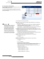
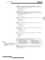
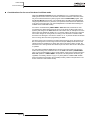
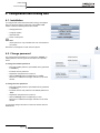
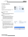
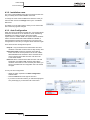
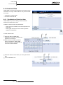
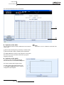
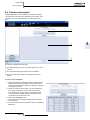
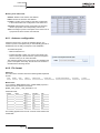
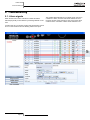
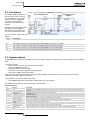
1
CSNET-WEB Technical Catalog Utopia & Set-Free Series Network System TCGB0038-rev.0 - 11/2006 - Printed in Spain CSNET-WEB Technical catalogue General characteristics 1 Installation 2 Operation and configuration 3 Configuration and viewing files 4 Troubleshooting 5 The specifications in this manual are subject to change without previous notification to ensure that HITACHI can offer the latest innovations to its customers. HITACHI does not assume any responsibility for possible damage caused by the use of this software. The damage caused to persons or material damage related directly to the use of this software is specifically excluded. Page 1 TCGB0038-rev.0 - 11/2006 CSNET-WEB Technical catalogue Contents 1. General characteristics __________________________________________________________ 4 1.1. Distributed system _________________________________________________________ 4 1.2. Based on Java technology ___________________________________________________ 4 1.3. LAN connection ____________________________________________________________ 4 1.4. Internet connection _________________________________________________________ 5 1.4.1. Via a LAN ________________________________________________________________ 5 1.4.2. Direct ___________________________________________________________________ 5 1.4.3. Proxy ___________________________________________________________________ 5 1.5. Improved interface _________________________________________________________ 6 1.5.1. 1.5.2. 1.5.3. 1.5.4. 1.5.5. 2. New overall view __________________________________________________________ 6 New timer ________________________________________________________________ 7 Improved power consumption option ___________________________________________ 7 Improved historical data option _______________________________________________ 7 New features _____________________________________________________________ 8 Installation ____________________________________________________________________ 9 2.1. Security summary __________________________________________________________ 9 2.2. Identifying the elements _____________________________________________________ 9 2.3. Specifications ____________________________________________________________ 10 2.4. Installation _______________________________________________________________ 10 2.4.1. Securing the device _______________________________________________________ 10 2.4.2. Electrical connection ______________________________________________________ 11 2.5. Hardware configuration _____________________________________________________ 12 2.5.1. Connection to the CSNET WEB interface. ______________________________________ 12 2.5.2. Connecting to CSNET WEB to configure the software ____________________________ 13 2.5.3. Installation of the CSNET WEB software and of a shortcut in your PC ________________ 14 3. Operation and configuration _____________________________________________________ 15 3.1. Area tree ________________________________________________________________ 20 3.2. Table of indoor units _______________________________________________________ 21 3.3. Operation panel: _________________________________________________________ 22 3.3.1. 3.3.2. 3.3.3. 3.3.4. 3.3.5. 4. Setting _________________________________________________________________ 22 Timer __________________________________________________________________ 23 Unit settings _____________________________________________________________ 27 System Status ___________________________________________________________ 28 Auto Cool/Heat __________________________________________________________ 30 Configuration and viewing files ___________________________________________________ 35 4.1. Installation _______________________________________________________________ 35 4.2. Change password _________________________________________________________ 35 4.3. System configuration ______________________________________________________ 36 4.3.1. 4.3.2. 4.3.3. 4.3.4. 4.3.5. Network settings _________________________________________________________ 36 Installation name _________________________________________________________ 37 Auto Configuration ________________________________________________________ 37 Time configuration ________________________________________________________ 38 Backup copy ____________________________________________________________ 38 Page 2 TCGB0038-rev.0 - 11/2006 CSNET-WEB Technical catalogue 4.4. Historical Data ____________________________________________________________ 39 4.4.1. Visualization of historical data _______________________________________________ 39 4.4.2. Values table _____________________________________________________________ 42 4.4.3. Download of historical data _________________________________________________ 43 4.5. Visualization of alarms _____________________________________________________ 43 4.6. Power consumption _______________________________________________________ 45 4.6.1. Autosave configuration ____________________________________________________ 46 4.6.2. File format ______________________________________________________________ 46 5. Troubleshooting_______________________________________________________________ 47 5.1. Alarm signals ____________________________________________________________ 47 5.2. Unit alarms ______________________________________________________________ 48 5.3. System options ___________________________________________________________ 48 Page 3 TCGB0038-rev.0 - 11/2006 CSNET-WEB Technical catalogue 1. General characteristics CSNET-WEB 1.1. Distributed system H-Link CSNET-WEB is a system of independent centralized control which can control up to 128 indoor and up to 16 outdoor units connected to Hitachi’s H-Link communication system. Air conditioning unit CSNET-WEB connects to a Local Area Network or Internet (using a DSL Router) by means of its Ethernet port, so that the parameters can be adjusted and monitored at a distance. Air conditioning unit Ethernet The internal memory for adjustments to the timer and the units allows CSNET-WEB to function independently after initial adjustment through a personal computer or similar device. CSNET-WEB does not need a dedicated computer to operate. Note Air conditioning unit Remote PC (initial adjustment) An initial adjustment is always required 1.2. Based on Java technology 1.3. LAN connection CSNET-WEB uses JAVA technology to control and monitor remotely operation of the installation. CSNET-WEB can be connected to a Local Area Network through its Ethernet port. After configuring the network, the system will be accessible from any site in the company’s network. If you want the CSNET-WEB application to run in a PC, it must have JAVA J2SE Runtime Environment installed. CSNET-WEB is supplied with a CD-ROM to ensure simple installation. Some adjustments are required for the LAN connection, and the network administrator’s assistance is needed. Remote PC CSNET-WEB H-Link Company LAN Hub Ethernet Air conditioning unit Air conditioning unit Air conditioning unit Remote PC Remote PC Page 4 TCGB0038-rev.0 - 11/2006 CSNET-WEB Technical catalogue 1.4. Internet connection CSNET-WEB has been designed to be accessible via Internet. This means maintenance is quick and effective, which satisfies the needs of the final user. Note: It is recommended that a dedicated DSL line is used in order not to interrupt the company’s network in the building. CSNET-WEB 1.4.1. Via a LAN CSNET-WEB can be connected to the Internet and to the company’d LAN using a router. The LAN has to be specially configured to guarantee security, using firewalls and antivirus software. Company’s LAN Remote PC Air conditioning unit Firewall Air conditioning unit Air conditioning unit Remote PC Remote PC Remote PC DSL modem 1.4.2. Direct Using the Ethernet port, CSNET-WEB can be connected directly to the Internet via a suitably configured DSL modem. This makes it is possible to monitor the system from any computer with Internet access. ... Internet This requires the assistance of the company’s LAN administrator. Remote PC CSNET-WEB Internet Remote PC Air conditioning unit Air conditioning unit Assistance from an IT expert is required. Security should also be ensured by external means such as firewalls and antivirus software. Air conditioning unit Remote PC ... Remote PC 1.4.3. Proxy A proxy is a network server which generally only allows access to WEB content. It is configured in the new proxy adjustment window which has been added to the Local software configuration, as shown later. CSNET-WEB Internet Firewall Notes: 1. Proxy will use NTLM1, Kerberos, Basic or Digest authentication. NTLM2 authentication is not permitted. Your network administrator should provide you with information about authentication. 2. The proxy and firewalls will allow communication through port 8080. Page 5 TCGB0038-rev.0 - 11/2006 Firewall Server Proxy Remote PC 1 CSNET-WEB Technical catalogue 1.5. Improved interface CSNET-WEB includes a new way of presenting information and the available program options. This new interface makes it easier to use and allows access to the system in a clearer and more comprehensible way. . 1.5.1. New overall view CSNET-WEB has five clearly differentiated control areas: 2 1 5 3 4 1 Area tree: Permits a conceptual ordering of the units. It can be organized into as many groups as you want. The root will always be Installation, and the indoor areas and units will be joined to this node. 2 Table of indoor units: List of all the indoor units with the basic information about their state of operation. 3 Operation panels: Control area for the operation of units. Page 6 TCGB0038-rev.0 - 11/2006 4 Configuration and file view: Gives access to the configuration of CSNET-WEB and to Historical Data and Power Consumption files. 5 Edition of area tree:Allows you to edit the Area Tree. CSNET-WEB Technical catalogue 1.5.2. New timer CSNET-WEB has a new improved timer which is easier to program. It can memorize up to 4 years of programming and lets you choose an annual timer independently for each unit and day. The daily Pattern lets you time the lock/unlock remote control functions as required, so you can control the system perfectly with greater comfort. It is easy to create a daily Pattern which can be assigned to the days required, and the timer can be easily assigned to specific units as required. Functions which can be locked Annual timer Daily pattern 1.5.3. Improved power consumption option CSNET-WEB lets you choose the period for which you control the proportion of power consumption of the indoor units compared to the outdoor, ranging from the data for a particular date to the data for a whole year. 1.5.4. Improved historical data option CSNET-WEB introduces the option of always showing historical data in the format of a table and graph, letting you analyse the problem immediately and find a solution easily. Page 7 TCGB0038-rev.0 - 11/2006 1 CSNET-WEB Technical catalogue 1.5.5. New features Autosave of the power consumption Adjustment of optional functions The use of of a 7-segment display on the CSNET-WEB interface makes installation and maintenance easy. New optional functions have been added which can be configured using the DSW switches: – Alarm notification: This is the selected by default. It shows when there is an alarm and indicates the code in a 7segment display. – IP notification: This function shows the current IP address in the 7-segment display, allowing the installer to make a connection when the IP configuration is different from the default. – Unit notification: CSNET-WEB will indicate the number of units detected. – Detailed alarm notification: This functions shows the installer the alarm code for each unit in the 7-segment display. Configuration of the backup copy Maintenance of CSNET-WEB has improved, and allows a backup copy to be made of the current configuration. If CSNET-WEB had to be replaced, the backup copy of the configuration file would restore the configuration of the new CSNET-WEB. Note: The passwords are not stored in the backup copy. They have to introduced again manually. Register of alarms Maintenance of the installation has been improved with the introduction of a register of alarms. The data show a detailed description of what happened for each alarm which has been produced. The information can be analysed from CSNETWEB or exported to a text file for later analysis. Download of historical data CSNET-WEB now lets you download the historical data starting with a particular date. The historical data can be stored in the new CSNET-WEB format or in a format compatible with previous versions of CSNET. CSNET-WEB stores up to 50 MB of compressed historical data. Depending on the installation and connection this option may take a few minutes. 50 MB of compressed data can store approximately the data of an installation of 128 indoor units for 3 months. Autosave of the error registry From the software adjustment window, you can configure the error registry to be saved automatically in the remote computer when there is an error. Page 8 TCGB0038-rev.0 - 11/2006 From the software adjustment window, you can configure the power consumption file to be saved daily in the remote computer. Installation list It is now easier to administer different CSNET-WEB installations from a remote PC. The new installation list lets you select a list of the latest connections. The user’s name and password can also be remembered by the software if required. This new feature makes the installation easier to use for users who connect regularly with different CSNET-WEB CSNET-WEB Technical catalogue 2. Installation 2.1. Security summary Warning Do not connect the electrical power to the control system until the preparation for the trial operation has been finalized successfully. Read this manual carefully before carrying out any installation work. Read the operation manual before configuring the air conditioning units. Warning Do not install CSNET-WEB in places... : - in which there is vapour, oil or spills. - in which there are sources of heat nearby (sulphurous atmospheres). - in which the accumulation, generation or leaks of inflammable gases have been detected. Warning Install CSNET-WEB away from possible generators of electromagnetic waves. Comply with the local electrical regulations. Use a power circuit which is not subject to surges in demand. Make sure that there is sufficient space around the CSNET-WEB (a minimum of 50 mm) for heat to dissipate properly (see “Installation procedure”). If the equipment is installed vertically, situate the power feed below and the control outputs above. HITACHI Web Controller oooooo - near the sea, or in saline, acid or alkaline atmospheres. 2.2. Identifying the elements The figure shows the name of each element of the CSNET-WEB interface. aJ 3 Rear view 1 2 aJ aJ aJ Front view from ‘A’ IN-OUT H-LINK LAN RS-422/485 RS-232 AC IN PC-CARD A Top view 1 H-LINK connector: Connected to the air conditioning equipment 2 LAN connector: Connected to the local area network 3 Network cable: Power feed entry 4 POWER: LED power indicator 5 H-LINK: LED indicator of transmission from the air conditioning equipment 6 RS-422/RS-485: LED indicator of transmission (not used) 7 RS-232-C: LED of transmission (not used) HITACHI WEB CONTROLLER 8 LAN: LED of LAN transmission. Shines when adjusting the LAN link 9 ERROR: LED indicator of abnormality. Blinks on error aJ Unused connectors 4 5 6 7 8 9 Page 9 TCGB0038-rev.0 - 11/2006 2 CSNET-WEB Technical catalogue 2.3. Specifications Hardware specifications Elements Specifications Power feed AC 230 V 1~ ±10% (50Hz) Consumption 10W (maximum) External dimensions Width: 240 mm, Length: 204 mm, Height: 74.5 mm Weight 1.94 kg Installation conditions Indoors (in a control panel, table-top) Ambient temperature 0~40 °C Humidity 20~85% (without condensation) Specifications for communication with the units Elements Specifications Communication with Outdoor units, Indoor units Communication cable Twin wire, without polarity Communication system Half-duplex Communication method Asynchronous Transmission speed 9600 Bauds Cable length Maximum 1000 m (total length) Number of units 16 outdoor units, 128 indoor units Communication specifications with a local area network Elements Specifications Communication with Processor at 1000 MHz, 256 MB RAM, 200 MB free hard disc space. Internet browser Any operating system which supports JRE (Java Runtime Environment), Java platform in a software environment developed by Sun Microsystems, allowing programs to be run in different operating systems Microsoft® Internet Explorer is a registered trademark of Microsoft Corporation 2.4. Installation When unpacking the equipment, make sure that it has not been damaged during transport. 3 mm 2.4.1. Securing the device AC IN Proceed as follows: 1 Remove the rubber base pads 2 Remove the 4 screws from the cover and take it off 3 Secure the box to the vertical back plate from inside with M5 screws (not supplied), using 3 mm washers outside to separate the box from the wall. 4 Replace the cover. Be careful to position the top correctly. Options Page 10 TCGB0038-rev.0 - 11/2006 CSNET-WEB Technical catalogue Warning: - Before switching on and starting CSNET-WEB you should make sure that: Warning: 1. All the cooling units and circuits are switched on and working correctly. 2. All the H-Link connections have been made. If any unit is not connected or without power when CSNET-WEB is started, it will not be recognized and will have to be configured later. - The signal cables should be a short as possible. Keep other power cables at a distance of at least 150 mm. Do not cable them together (although they may cross). If a joint installation is inevitable, take the following measures to prevent parasite currents: - Protect the signal cable with a metallic tube earthed at one end. - For communications, use a shielded cable earthed at one end. Danger: - Always disconnect the power from CSNET-WEB when manipulating the equipment to prevent electrocution. - Do not connect the interface to the network until the installation is complete. - Follow the local codification and safety rules strictly when connecting the installation to the electrical network. - A three-wire cable is needed for a connection to the network (two wires plus earth), with a suitable plug at one end. 2.4.2. Electrical connection In order to work, CSNET-WEB has to be connected to the electrical power network, the air conditioning equipment (H-Link) line and the Ethernet LAN. Cable specifications Transmission cable for the units (H-Link) Twisted pair cable 1P-0,75 mm². Without polarity. Insulated and earthed at one end. To select the type of cable, see the Outdoor Unit Installation and Operation Manual 2 LAN line Category 5 or above LAN cable - A cross-over cable is needed for direct connection to a PC. - A direct cable is needed for connection to a commercial distributor (Hub) 3 Network cable 2 phase + earth AC 230V 1~ 50 Hz Make sure that the cable used complies with local regulations and that both the plug and socket are correctly earthed. Local Area Network 2 Air conditioning units 1 LAN CSNET WEB NL Connection 1 After making the connections, replace the cover 3 Plug, power base and earthing should comply with local regulations. Page 11 TCGB0038-rev.0 - 11/2006 2 CSNET-WEB Technical catalogue 2.5. Hardware configuration After completing and checking the electrical installation, make sure that all the air conditioning units are working and apply power to the CSNET-WEB to configure the CSNET-WEB interface. 1. Connect the computer which will be used for the configuration to CSNET-WEB with a cross-over Ethernet cable. 2. Once the computer is connected, insert the CD-ROM supplied with the CSNET-WEB pack. If the autorun option is activated in Windows the installation program will start automatically. If this option is not activated, run the Autoinstall.exe application included in the CD-ROM. 3. The first setup page of CSNET-WEB Hardware & Software Setup will appear, showing three options: – Configure CSNET WEB Hardware (Change Network Settings): Change the TCP/IP configuration of CSNETWEB to adapt to the network in which it will be installed. – Connect to CSNET-WEB Software for Configuration: Connect to the CSNET-WEB application to configure all the elements explained in the following chapter. – Install CSNET-WEB software and direct access in your PC: to install the CSNET-WEB application in your PC and then in computers of the same network which are going to use CSNET-WEB. < Back Next > Cancel < Back Next > Cancel < Back Next > Cancel 2.5.1. Connection to the CSNET WEB interface. 1. Select “Configure CSNET-WEB Hardware (Change Network Settings” and the screen “Select Network Card” will appear, showing the network adaptors available on your PC. 2. Select the network adaptor you are going to use and press Next. We recommend choosing the Local area connection if the system does not already have a specific network (the network administrator will help you make the correct choice). 3. The screen “CSNET WEB Hardware Settings” will appear. Here you can change the TCP/IP setting of CSNET WEB. To configure CSNET WEB introduce the password in the “INSTALLER PWD” field. The default password is “Installer” (case-sensitive), but this can be changed later. The HW IP ADDRESS, HW NETMASK and HW GATEWAY fields should contain the network settings required for CSNET WEB and supplied by the network administrator. Click on Next to continue. Page 12 TCGB0038-rev.0 - 11/2006 CSNET-WEB Technical catalogue 4. The display “Time, date & zone configuration” will appear. Introduce the date and time. Select the zone which is closest to the geographical area of the installation. Click on Next to configure CSNET WEB. The installation program will show the following message to remind you that 2 minutes are needed to apply the configuration. OK 2 < Back Next > Cancel < Back Next > Cancel After the TCP/IP configuration of CSNET WEB is complete, the software setup will return to the initial screen. 2.5.2. Connecting to CSNET WEB to configure the software This option lets you change the PC network settings temporarily and connect to the CSNET WEB interface. Warning: We recommend that you do not configure the software without configuring the CSNET WEB interface first. 1. Select Connect to CSNET WEB Software for Configuration, press Next and the Select Network Card window appears, showing the network adaptors available in your PC. 2. Select the network adaptor you are going to use and press Next. We recommend you choose Local area connection if the system does not already have a specific network (the network administrator will help you make the correct choice). Page 13 TCGB0038-rev.0 - 11/2006 CSNET-WEB Technical catalogue 3. Introduce the IP of the CSNET WEB you want to connect to. The configuration you have already chosen appears by default. You should always introduce the temporary IP the PC has to use. Warning: If the PC and CSNET WEB interface are connected to a local area network, the network configuration should be supplied by the network administrator. Otherwise, use a valid configuration within the range set for the CSNET WEB interface. In case of doubt, consult the network administrator. 4. Press Next to validate the changes, change the PC network configuration temporarily and start the CSNET WEB application which configures the system. 5. When the application starts it configures the system as indicated in chapter 4. < Back Next > Cancel 6. After completing the configuration close the CSNET WEB application and choose Accept in the message Waiting for CSNET WEB to finish.... The installation will return to its initial screen. OK 2.5.3. Installation of the CSNET WEB software and of a shortcut in your PC Proceed as follows to install the CSNET WEB application on your PC and/or on computers in the same network which have to be connected with the CSNET WEB interface: 1. Once the computer is connected, insert the CD-ROM supplied with the CSNET-WEB pack. If the autorun option is activated in Windows the installation program will start automatically. If this option is not activated, run the Autoinstall.exe application included in the CD-ROM. 2. When the first installation page CSNET WEB Hardware & Software Setup appears, select Install CSNET WEB software and direct access in your PC Warning: < Back Next > Cancel < Back End > Cancel In order to run, the CSNET WEB application requires Java J2SE Runtime Environment to be installed in your PC. If it is not correctly installed, carry out step 3. In case of doubt, or if it is installed, go to step 4. If still in doubt, consult the network administrator. 3. Press the Install button of Java J2SE Runtime Environment 5.0. The Java installation application will start. 4. Press the Install button of CSNET WEB Software to install the CSNET WEB application. 5. Press End to exit the CSNET WEB installation. Page 14 TCGB0038-rev.0 - 11/2006 CSNET-WEB Technical catalogue 3. Operation and configuration After configuring the CSNET WEB interface you should begin the configuration of the system Note: CSNET WEB needs at least the following to be configured: – Local software configuration (see next page) – Area tree (see chapter 3.1) – Configuration of the unit (see chapter 3.3.3) – Auto Cool/Heat (see chapter 3.3.5) 3 We recommend configuring the other points indicated in the manual at the same time, although this can be done later. Warning Remember that to access CSNET WEB by a shortcut you need to connect the computer to the Ethernet connection connected to the CSNET WEB interface. When you click on the shortcut, a page appears in which you have to specify the language you want to use. The same screen shows a second timer (this can be configured later), which runs down to zero and then runs CSNETWEB in the selected language. If you wait 10 seconds or press the Accept button, CSNET WEB will show the Initial Page. Initial page The initial page is divided into two parts: 1 Access to the installation required 2 Local Computer Configuration: for the different addresses of the installations you want to connect to from the computer you are using. When you try to access to the required installation, the initial screen shows three text fields which have to be completed to access the installation: – Installation: Enter the IP address of the CSNET WEB to which you want to connect – User ID: Enter the name of the type of user who will access the installation. There are two types of user: – “Installer”: Has access to all the options. We recommend that only authorized people who know the program have access to this option. – “User”: Only has access to the Configuration of the units and visualization of the Timer. Note: The User ID is case-sensitive Page 15 TCGB0038-rev.0 - 11/2006 1 2 CSNET-WEB Technical catalogue – Password: Write the password of the user you have entered. – The default password for the “Installer” is: Installer – The default password for the “User” is: User – Using a proxy: As can be seen in the Local Computer Configuration section, if you select this option, the connection will be made through a proxy (if one is configured). Once all the data have been introduced, press the “Accept” button. If you are accessing this installation for the first time, the message “New installation” will appear: If you click “Yes”, the data introduced will be saved. In this way, each time you start CSNET WEB in the “Installation” text field, you will see a drop-down menu with the different installations saved. Next, CSNET WEB will connect to the installation you have entered, and show the main screen. Local Computer Configuration: As indicated above, the initial screen shows the Local Computer Configuration button for the different installation addresses you may want to connect to from the computer you are using. If you click this button the following screen appears: This screen lets you configure the operation of the software in your computer in terms of: – Installation list. – Proxy settings, and – CSNET WEB settings. Page 16 TCGB0038-rev.0 - 11/2006 CSNET-WEB Technical catalogue – Installation list: The default screen. It lets you add, edit or delete the following installation data: – name of the installation – connection port address – proxy use – user ID (Installer or User) – password – the option of saving the password To create a new installation: press the “New” button, and the “New Installation” window appears. Enter the name of the installation and the IP address. If you want CSNET WEB to remember the user ID and password, select “Yes” in “Remember Password”, and then write the user ID and password, and confirm the password. Press “Accept” to save the changes and return to the installation list. In this way, when you enter the initial screen again, the “Installation” drop-down menu will include the names of the installations introduced previously. Page 17 TCGB0038-rev.0 - 11/2006 3 CSNET-WEB Technical catalogue The next screenshot shows the table with two installation entries. – Proxy Settings: The “Proxy Settings” tab lets you configure the connection through a proxy if necessary. If you have any doubts about the data you need consult your network administrator. – Software Settings: This tab lets you configure two kinds of data: – Language settings:You can choose the default language to be used in the main screen. You can set the countdown time (in seconds) and make the program remembers the changes. – Local data storage: The chapters “Alarm Visualization” and “Power Consumption” will give more details about these settings. Page 18 TCGB0038-rev.0 - 11/2006 CSNET-WEB Technical catalogue Main screen Once you have chosen the installation you wish to access, the following screen appears. The different parts of the screen have to be configured as shown in the following chapter. 2 1 5 3 4 1 Area tree: Orders the units on a conceptual basis. It can be organized into as many groups as you want. The root will always be Installation, and the indoor areas and units will be joined to this node. 2 Table of indoor units: List of all the indoor units with the basic information about their operating state. Page 19 TCGB0038-rev.0 - 11/2006 3 Operation panels: Control area for the operation of units. 4 Configuration and file view: Gives access to the configuration of CSNET-WEB and to Historical Data and Power Consumption files. 5 Edition of the area tree: Allows you to edit the Area Tree. 3 CSNET-WEB Technical catalogue 3.1. Area tree “Enable Area Edition” activates an area tree for this installation. - New:Creates a new area - Edit: Edits the selected area in the area tree - Delete: Deletes the selected area - Up: Moves the selected area up, respecting its level - Down: Moves the selected area down, respecting its level - Update: Saves all the areas created and closes the Area Edition - Cancel: Closes the Area Edition without saving changes made. Note: The areas created contain indoor units. See the following chapter if you want to select to which area each of the units belongs. Page 20 TCGB0038-rev.0 - 11/2006 CSNET-WEB Technical catalogue 3.2. Table of indoor units The Table of indoor units is composed of a row for each indoor unit 3 The meaning of each column is as follows: Column Location Content / Symbol OU Address of the Outdoor Unit or cooling circuit to which the Indoor Unit belongs <number> IU Address of the Indoor Unit <number> RCS Remote Control Number <number> Area Area to which the selected unit belongs +<descriptive text> Location Name of the room conditioned by the selected unit <descriptive text> On/Off Indicates the On/Off situation of each Indoor Unit On Off Control Indicates whether the Indoor Unit has a locked control parameter which cannot be changed from the Remote Control Parameter locked No parameter locked Tset Setting temperature <number> Mode Operation mode of indoor unit Cool Fan. Indoor unit fan level: Low Louver Position of the baffle plate. On Heat Medium Timer used by the indoor unit Page 21 TCGB0038-rev.0 - 11/2006 Fan Automatic High Not available ... Timer Dry <descriptive text> CSNET-WEB Technical catalogue 3.3. Operation panel: The Operation Panel has five access fields offering complete control of the units: – Setting – Timer – Unit Configuration – System Status – Auto Cool/Heat Each of these fields is explained below: 3.3.1. Setting This option shows the parameters which can be selected for each indoor unit 1 2 3 After selecting the parameters to be adjusted, press Update to send the order to the units selected or Cancel to cancel the operation. 1 Select the unit The unit selected in the table of indoor units is identified by the Location field. Using the Set by field, select the group of units whose parameters you want to adjust: - Unit: The unit selected - Outdoor: All the indoor units which belong to the same cooling circuit. - Area: All the units which are in the same area - All units: All the units controlled by CSNET-WEB Page 22 TCGB0038-rev.0 - 11/2006 2 Adjust parameters Click with the mouse on the parameter you want to select. Select the temperature with the buttons “” or “” The temperature margin is: - From 19ºC to 30ºC for Cooling - From 17ºC to 30ºC for Heating Select the fan speed and the position of the baffle plate by pushing the Fan speed and Louver buttons 3 Parameter lock The parameters selected in RCS Lock will remain locked in the position they were in when the option was activated. This means they cannot be modified from the Remote Control. CSNET-WEB Technical catalogue 3.3.2. Timer This option shows the operation times which can be chosen for each indoor unit The Timer shown corresponds to the unit chosen in the table of indoor units, as shown in the example. The Timer is composed of: 1 2 3 3 4 aC aB aA Edition and assignation aJ 1 2 3 4 5 Pattern 6 7 8 Timer 9 aJ aA aB aC 9 8 7 Button for editing the pattern and timer Button for assigning the timer to the units selected Field for selecting the units to which you want to assign the timer Selection of programmed pattern Parameter lock Lock Unlock Programmed fan speed: Lo Me Setting temperature: ºC / Unchanged Programmed operation mode: Cool Heat Dry On/Off selection: Off Fan On TCGB0038-rev.0 - 11/2006 5 Unchanged Hi Programmed time Information from selected month Field for selecting month and year you want to visualize Field to select programmed timer Page 23 6 Automatic Unchanged Unchanged Unchanged CSNET-WEB Technical catalogue Access to programming To create the pattern and timer push the Edit Timer and Patternbutton: With the following functions: 1 Area to update and close programming. 1 2 3 4 2 Area to create New, Edit and/or Delete programmed timer. 3 Area to create New, Edit and/or Delete timer to be programmed. 4 Entries for the Daily Pattern you program. 5 Area to create New, Edit and/or Delete an entry of the programmed pattern. 6 Programmed annual timer. 6 5 Programming of daily pattern After accessing the Timer program zone, follow the instructions below. For more details of the programmable parameters, see the previous page. – Creating a new pattern: 1 1 Press the New button 2 Enter the name of the new pattern in the box indicated: e.g. “Pattern 1” 3 Select the colour using the palette selection by double clicking on it. 4 After completing this stage, press Update to program the time of the new pattern. Note: After updating the pattern, the first pattern you programmed is shown. For the following steps, select once more the pattern you have just created. – Edition of an existing pattern: – Select an existing pattern using the field in the drop-down menu. – Press the Edit button. – Modify the colour of the selected pattern as indicated for creating a new pattern. – Modify the daily program as indicated for daily programming. – Deleting an existing pattern: – Select an existing pattern using the field in the drop-down menu. – Press the Delete button. Page 24 TCGB0038-rev.0 - 11/2006 2 3 4 CSNET-WEB Technical catalogue – Daily programming: After creating and selecting the pattern you can begin to program each of the entries, indicating the conditions of work at each time of day. – Press the button New to move to the entry program mode. – Select the option you want to program in each field. Find the “Timer” sub-field. – Select it, and press the Acceptbutton. The entry program which appears depends on the pattern selected. 3 – Press the Edit button to modify an entry which has been created and selected previously. – Press the Delete button to delete an entry which has been created and selected previously. Page 25 TCGB0038-rev.0 - 11/2006 CSNET-WEB Technical catalogue 1 Timer programming 2 After accessing the Timer program zone, follow the instructions below. – Creating a New Timer 1 Press the Newbutton 2 Enter the name of the new timer in the box indicated: e.g. “Winter” 3 Press Update to move to the program of the selected month. 3 – Monthly programming Allots the daily pattern selected previously for each day of the month, as indicated below: – Select the daily patron using the drop-down menu 5 1 By pressing the day of the week, the pattern selected previously is assigned to all the days of the month corresponding to the day of the week selected. 2 Pressing a particular day assigns the selected pattern only to this day. 1 3 Pressing the arrow >> assigns the selected pattern to all the days of the month. 2 4 Pressing the name of the month assigns the selected pattern to it. 5 After setting the timer, press the Update button to confirm the programming. Page 26 TCGB0038-rev.0 - 11/2006 3 4 CSNET-WEB Technical catalogue Assigning the timer After the Timer has been created, you can assign it to all the units which have to use it. Do this as follows: 1 – Press the 1 field button from the drop-down menu to select the units to which you want to assign the timer. The list includes the following options: Unit: Select the unit marked in the table of indoor units Area: Select all the units found in the same group as the unit marked in the table of indoor units. Outdoor: Select all the indoor units connected to the same outdoor unit as the unit marked in the table of indoor units. All Units: Select all the indoor units – Press button 2 Assign Timer to: to assign the timer to the units selected 3.3.3. Unit settings The unit settings show all the data of each of the units controlled by CSNET WEB. The Timer shown corresponds to the unit chosen in the Table of Indoor Units, as in the example. The information given is as follows: Location: Name of the room conditioned by this unit. Area: Zone to which this unit belongs. IU Type: Model of indoor unit (recognized by the system). (see Note 1) IU Model: Exact model of the indoor unit (see Note 2) OU Type: Model of the outdoor unit connected to this indoor unit (recognized by the system) (see note 3) OU Model: Exact model of the outdoor unit connected to this indoor unit (see Note 2) Is FX: If you mark the check box, this unit corresponds to a 3-tube unit (FXG or FXN) Is R410A: If you mark the check box, the cooling system used is R410; if you do not mark it, the cooler is R407C. (see Note 6) IU Serial No: Serial number of the outdoor unit to which the indoor unit is connected (see Note 2) Page 27 TCGB0038-rev.0 - 11/2006 2 3 CSNET-WEB Technical catalogue OU Serial No: Note 2) Serial Number of the indoor unit (see Notes: 1. If the indoor unit is RPC or RPK, CSNET WEB will display RPC(RPK), as they cannot be identified correctly. RCS Group: Remote control number used by more than one indoor unit including this one, for example 1. A second group should have a different number, etc. If any of the parameters within a group changes, all the groups which form it will adopt the specified value at the same time. This process is automatic and there is no need to select the unit group to change. (see Note 4) 2. The precise model should be entered to make necessary maintenance and repair work easier. 3. There following are possible types of outdoor units: – RAS-#.# (UTO): Utopia and Utopia Big CH Box: Number of the CH (Cool/Heat) distribution box used by more than one indoor unit including this one. – RAS-#.# (INV): Utopia Inverter – RAS-#.# (SF): Set-Free and Mini Set-Free When the automatic cooling/heating operation has been chosen, a common number in this field has to be chosen to ensure that all these units change their operating mode simultaneously. 4. It is not possible for two or more units with a remote controller to function in different conditions. Only use the remote control Group within the same cooling system or CH Box. Do not use a single controller to control indoor units connected to different outdoor units or HC boxes. If the operation mode of one of the units in this group is changed, CSNET-WEB will also change the mode of operation of the other units of the same group which no longer have a compatible operation mode. (see Note 5) 5. The compatibility of the operation modes is as follows: Operation Mode Compatible modes in the other units of the same group Cool Cool, Dry, Fan Heat Heat, Fan Dry Cool, Dry, Fan Fan Cool, Dry, Heat, Fan Automatic Cooling / Heating Automatic Cooling / Heating 6. This information will be used by CSNET WEB to calculate the control parameters of the cooling system, like TdSH. 3.3.4. System Status The System Status field shows the operating conditions of each of the units controlled by CSNET WEB. The System Status shown corresponds to the same unit selected in the Indoor Unit Table, as shown in the adjoining example. Description The information display is divided into 4 parts: – Data of the Indoor Unit – Setting data of the Remote Control and/or the Configuration field – Data of the Outdoor Unit – Alarm produced and reason for the Compressor status Page 28 TCGB0038-rev.0 - 11/2006 CSNET-WEB Technical catalogue Explanation of the fields Although all all these parameters are available in the 3-tube systems (Set-Free FX), some are not in other systems. These are indicated in the table. 1 2 3 4 8 5 20 21 22 23 6 7 9 Set-Free FX Real vent speed Setting temperature Selected operation mode: Selected fan speed Model of outdoor unit and its power Discharge pressure Suction pressure Discharge overheating (TdSH) Discharge gas temperature Compressor frequency Total consumption of compressors Number of compressors operating MV1 expansion valve opening MV2 expansion valve opening MV3 expansion valve opening/MVB Ambient temperature Evaporating temperature (Heating) Number and description of alarm Last cause of Compressor stop (3) O = Available — = Not available Set-Free FS Alarms Mini Set-Free Outdoor Unit DC-Inverter 29 30 Group Description Indoor Unit Model of the indoor unit and its power Thermo On/Off Off/On Filter time Air outlet temperature Air inlet temperature Optional remote thermistor Gas piping temperature Liquid piping temperature Expansion valve opening Real operation mode Remote Control 28 Utopia N 12 13 14 15 16 17 18 19 20 21 22 23 24 25 26 27 28 29 30 10 Utopia G No. 1 2 3 4 5 6 7 8 9 10 11 11 12 27 24 25 26 — — — h ºC ºC ºC ºC ºC % ºC O O O O O O O — O — O O O O O O O O O O O O O O O O O O O O O O O O O O O O O O O O O O O O O O O O O O O O O O O O O O O O O O O — — — — — MPa MPa ºK ºC Hz A — % % % ºC ºC — — O O O O O — — — O — O O — — — O O O — O O O O O — — — O — O O — — — O O O O O O O O O — — — O O O O O — — O O O O O O O O O O O O O O O O O — — O O O O O O O O O O O O O O O O O (1) (2) O O O O O O O O O O O O O O O O O O O O O O O Units 13 14 15 16 19 17 18 Alarms Notes: 1 Not for FS units of up to 10 HP 2 Not for FS units of up to 20 HP 3 The value shown does not disappear until the cause of the compressor stop does not change. Page 29 TCGB0038-rev.0 - 11/2006 The alarms shown in CSNET WEB are the same that can be found in the service manual of the outdoor unit in question. Cause of compressor stop The cause of the compressor stop shown in CSNET WEB is the same that can be found in the service manual of the outdoor unit in question. 3 CSNET-WEB Technical catalogue 3.3.5. Auto Cool/Heat The Set-Free FS3/FSG/FSN, Mini Set-Free FSVG/FSVN, DC-Inverter HVRG/ HVRN/HRN and Utopia HG/HVG/HN/HNV are 2-tube systems and are not designed to operate in the automatic Cool/Heat mode when more than one indoor unit is connected to the same outdoor unit, but only in the cool or heat mode. Thus all indoor units connected to the same outdoor unit should be changed from one mode to another at the same time. The same is applicable to the 3-tube Set-FREE FXG/FXN systems, for all indoor units connected to the same CH Box. However, operation in the automatic Cool/Heat mode is available through CSNET WEB. In temperate seasons, CSNET WEB calculates the main need of the indoor units for each of the outdoor units in the systems mentioned above, selects the mode needed for most of the units in the system and adjusts the remote controller accordingly. With the aim of giving the system time to be established in a particular mode, its requirements are checked for at least 20 minutes after the last change carried out. This process is continuous for as long as the indoor units are set to Auto. If the systems are correctly designed, i.e. if all the indoor units of the same outdoor 2-tube unit have similar cooling and heating demands, then it is possible to completely automate heating in the morning (for example), cooling in the afternoon and heating once more at night. Users maintain local control over the temperature in the room by the remote control. There are two ways in which CSNET can decide whether the operation mode should be established in AUTO: Description of the operation mode In the automatic (Auto) Cool/Heat mode requested by the indoor units, CSNET WEB will check first whether the cooling circuit to which the unit is connected is 2 tube or 3 tube (see note in margin) before deciding to change the operating mode. Next, CSNET WEB will calculate the difference to decide the best operation mode at that moment. Note: 2-tube models: Set-Free FS3/FSG/FSN, Mini Set-Free FSVG/FSVN, DC-Inverter HVRG/HVRN/HRN, Utopia HG/HVG/HN/HNV y CH Box of FXG/FXN with a CH Box connected to various indoor units 3-tube models: FXG/FXN with an independent CH Box Page 30 TCGB0038-rev.0 - 11/2006 CSNET-WEB Technical catalogue The temperature difference is calculated as follows: 2 Tubes: CSNET WEB takes into account all the indoor units which depend on the same cooling circuit. CSNET WEB then calculates in the following way: Temp. diff. (1) = Air inlet temp. (1) - corrected temp. (1) Temp. diff. (2) = Air inlet temp. (2) - corrected temp. (2) …. Temp. diff. (n) = Air inlet temp. (n) - corrected temp. (n) Temp. diff. = (Temp diff. (1) + Temp diff. (2) + ... + Temp diff. (n)) / n Where: Air inlet temp. (i) = Air inlet temperature selected (consult the section “Description of Parameters” for more information) Corrected temp. (i) = Temperature shown in the Remote Control or selected by CSNET WEB (if the indoor unit does not have a Remote Control) (see the section “Description of Parameters” for more information) Note: If more than one indoor unit is connected to the same CH Box, CSNET treats this box as an outdoor 2-tube unit. Temp. diff. (i) = Temperature difference between the air inlet temperature and the setting temperature of the indoor unit number “i” n= Number of indoor units connected to the same outdoor unit Temp. diff. = Average of the temperature differences of all the indoor units. 3 Tubes CSNET will only make this calculation for the indoor units in Auto mode. Thus CSNET makes independent calculations for each indoor unit: Temp. diff. = Air inlet temp. - Corrected temp. Where: Air inlet temp = Air inlet temperature selected (consult the section “Description of Parameters” for more information) Corrected temp = Temperature shown in the Remote Control or selected by CSNET WEB (if the indoor unit does not have a Remote Control) (see the section “Description of Parameters” for more information) Temp. diff. = Temperature difference between the air inlet temperature and the setting temperature of the indoor unit After calculating the operation mode which the units should use, and taking into account the conditions established as indicated in “Description of Parameters”, CSNET WEB will send the order to all the affected units. Page 31 TCGB0038-rev.0 - 11/2006 3 CSNET-WEB Technical catalogue Description of Parameters To use this option, you have to set the parameters shown in the Auto Cool/Heat Operation Panel. The Auto Cool/Heat panel shown corresponds to the cooling circuit of the indoor unit selected in the table of indoor units, as shown in the example. You should adjust the following parameters: Warning: Master Unit: Field for selecting the method CSNET WEB will use to calculate the Temperature Difference. When this method is used (marked), the following outdoor unit option cannot be used: “control of indoor unit fan speed” (during operation with the thermostat deactivated in heat mode, the indoor fan stops for 6 minutes and operates for 2 minutes). If it is used, the decision of when to change will not always be correct (if it is measured during the deactivation cycle of 6 minutes) – (Marked): CSNET WEB will only use this unit to calculate the temperature difference and decide the change, not taking into account the other units connected to the same 2-tube cooling circuit. – (Not Marked): CSNET WEB will use the average temperature difference of all the indoor units connected to the same 2-tube cooling circuit. Use Remote: Field for selecting what inlet temperature CSNET WEB should use to calculate the temperature difference if an optional remote temperature is connected in THM4 of the PCB of the indoor unit. – (Marked): CSNET WEB will use the optional remote sensor. – (Not Marked): CSNET WEB will use the average of the temperature between the optional remote sensor and the inflow temperature. MINOAT: Minimum outdoor ambient temperature for Cool operation. – Preset adjustment: +10 °C – 1 °C steps. – 0 °C... 40 °C.margin. MAXOAT: Maximum outdoor ambient temperature for Heat operation. – Preset adjustment: +20 °C – 1 °C steps. – 0 °C... 40 °Cmargin. – MAXOAT should be higher than MINOAT – MAXOAT should be lower than the dry bulb (DB) temperature equivalent to the margin of maximum outdoor ambient temperature for the Heat mode: The margin of maximum outdoor ambient temperature for Heat mode of the outdoor unit is 15.5 WB Equivalent dry bulb temperature: Relative humidity of 95% = 16 DB Relative humidity of 77% = 18 DB Relative humidity of 62% = 20 DB Relative humidity of 50% = 22 DB, etc. Page 32 TCGB0038-rev.0 - 11/2006 CSNET-WEB Technical catalogue USERMIN: Minimum Setting temperature. If the selected temperature is lower, CSNET WEB will use USERMIN as the value for the Setting temperature, changing this value as soon as the operation mode changes. – Preset adjustment: +20 °C – 1 °C steps. – 17 °C... 30 °Cmargin. USERMAX: Maximum Setting temperature. If the selected temperature is higher, CSNET WEB will use USERMAX as the value for the Setting temperature, changing this value as soon as the operation mode changes. – Preset adjustment: +25 °C – 1 °C steps. – 17 °C... 30 °Cmargin. HYSTC: Value of the temperature difference calculated to pass from Heat to Cool mode. – Preset adjustment: + 2°C – 0.1 °C steps. – 1 °C... 2 °Cmargin. HYSTH: Value of the temperature difference calculated to pass from Cool to Heat mode. – Preset adjustment: 1.3 °C – 0.1 °C steps. – 1 °C... 2 °Cmargin. DELAY: The time which must elapse between the last change of operation mode to the next change. – Preset adjustment: 20 min – 10 min steps – 20 min... 60 min margin. DIFF: Temperature corrected on changing the operation mode, to ensure greater comfort. – Preset adjustment: 0 – 1 °C steps. – Margin: 0, 1, 2 – DIFF The Setting temperature is adjusted using the following formula when the operation mode is changed, depending on the DIFF option selected: Note: DIFF Change from Cool to Heat Change from Heat to Cool 0 Corrected temp = Setting temp Correctedtemp = Setting temp 1 Corrected temp = Setting temp + 0 Corrected temp = Setting temp + 1 The remote control and the CSNET2 Corrected temp = Setting temp - 1 Corrected temp = Setting temp + 1 WEB always show theCorrected temperature. (the result is the setting Where: temperature) Corrected temperature: Temperature used to calculate the change of operation mode Setting temperature: Temperature selected by CSNET WEB or by the Remote Control of the indoor unit. Page 33 TCGB0038-rev.0 - 11/2006 3 CSNET-WEB Technical catalogue Considerations for the use of the Auto Cool/Heat mode When the automatic Cool/Heat is used, the difference of 4 °C programmed in the heating mode of each indoor unit should be cancelled in all of them. Otherwise, there may be a conflict between the system program and the CSNET WEB program. (See the Service Manual of the indoor unit for details about cancelling this misadjustment using the optional function b1). However, if an optional remote sensor has been fitted in the rooms (one per indoor unit), the misadjustment is cancelled automatically (not available in the FSGM RPK series). If an indoor unit is defined by CSNET WEB in Auto C/H mode, all the indoor units connected to the same outdoor Set-Free FS (or to the same CH Box in Set-Free FX systems) will change to the Auto C/H mode. This means that, for example if one of the indoor units was adjusted for heating at 17 C and the outdoor Set-Free FS or Set-Free FX CH Box changes to cooling mode, according to the calculation of CSNET WEB, this indoor unit will begin to cool when it reaches 17 °C. To prevent this kind of situation from occurring, take care when programming the timer. For all the indoor units connected to a single outdoor Set-Free FS or Set-Free FX CH Box, the starting time in the morning for the first unit (see Timer) should serve as the reference time and conditions for all the other units in the same system. At night, the last indoor unit to change will be the reference point for all the other units of the system in question. If a user selects a different mode with the remote control (PC-P1HE type) when the local mode is being used, it will later return to the mode calculated by CSNET WEB. Thus it is not recommended to use the mode selector of the remote controls during the Auto C/H operation of CSNET WEB in local mode. The temperature should only be regulated, if necessary, with the (up) or (down) buttons. CSNET WEB will then select and adjust the necessary (and possible) mode by outdoor unit (also in the LCD screen of the PC-P1HE remote control). Page 34 TCGB0038-rev.0 - 11/2006 CSNET-WEB Technical catalogue 4. Configuration and viewing files 4.1. Installation To configure and access the historical and energy consumption files you should access the bottom left of the CSNET WEB window, where the following buttons are located. – Change password – Configure System – Historical Data – Power Consumption Note: These options are only available if the user has entered as an Installer. Next there is a description of each of these options: 4.2. Change password The change password panel lets you change the “Installer” or “User” password. The two types of users are in two separate boxes. To change the Installer password: – Enter the installer password. (The default factory password is “Installer”). – Introduce the new password. – Repeat the new password to confirm it. – Click the Change button corresponding to “Installer Password” to validate the changes and return to the main window. To change the User password: – Enter the Installer password. (The default factory password is “Installer”). – Introduce the new user password. The default password is “User”. – Repeat the new password to confirm it. – Click the Change button corresponding to “User Password” to validate the changes and return to the main window. To cancel the changes and return to the main window, click the Close button. Page 35 TCGB0038-rev.0 - 11/2006 4 CSNET-WEB Technical catalogue 4.3. System configuration The CSNET WEB configuration has 4 sections: 1 Network settings 2 Installation name 1 3 Auto Configuration 2 4 Time configuration 3 4 5 Backup copy 5 The Close button cancels all the changes made in the system configuration and returns you to the main window. 4.3.1. Network settings Warning: If this is the first time that CSNET WEB is being run in this installation, we recommend using the CD supplied with the interface, as explained in section 2.5. Warning: The network settings specify the parameters for configuring CSNET WEB to be able to communicate with the rest of the network. These parameters are essential, and a bad configuration may cause conflicts in the local area network. This is why we recommend that for making these settings you get in touch with the network administrator where CSNET WEB will be installed. To enter and/or modify the network configuration follow these steps: 1. Enter the IP address. The IP address consists of four numbers which must be between 0 and 255. 2. Enter the Mask. As in the case of the IP address, the four numbers must be between 0 and 255. 3. Enter the IP address of the Gateway. Again, the numbers for these four fields follow the same rule as the IP address and Mask. If you do not have a Gateway, the field should contain an IP address within the margins of the specified network. 4. Click on the Change button situated in the upper right (by the IP line). A message will appear as in the example: 5. When you press the Accept button, the program will close, and you will have to wait about two minutes before restarting CSNET WEB. Page 36 TCGB0038-rev.0 - 11/2006 CSNET-WEB Technical catalogue 4.3.2. Installation name The name of the installation is the title of the main window. This lets you identify where CSNET WEB is connected. To change the name of the installation first enter the name you want and then click on the Change button by the “Installation Name” line. This takes you to the main window, where you can see that the title of the main page has changed. 4.3.3. Auto Configuration When the system is started for the first time, it recognizes all the machines connected to H-Link. With time, the air conditioning installation may undergo changes which have certain repercussions on CSNET WEB. If the system detects machines which have been added after CSNET WEB was installed, or that machines have been removed from the H-Link, the Auto Configuration function lets you recognize all the machines again. There are three Auto Configuration options: Keep All: Only the machines found are added. The other machines in the table of indoor units are kept as they were. Delete Not Found: If there are machines in the table of indoor units which are not present in the H-Link, CSNET WEB will delete these machines. All the machines which were not present in the table of indoor units but in the H-Link will be added. Delete all: All the machines in the table of indoor units will be deleted, and CSNET WEB will again detect all the machines connected to H-Link. Once they are added, you have to remember that the configuration has to be carried out again. To carry out Auto Configuration: – Select the option required in the Auto Configuration selection table – Press the Start button at the right of the menu. – If you return to the main window, you will see the progress as a percentage (%) in the bottom left of the screen. Page 37 TCGB0038-rev.0 - 11/2006 4 CSNET-WEB Technical catalogue 4.3.4. Time configuration The time configuration is used to synchronize CSNET WEB with your time zone. It is very important that this configuration is correct for the timer to work correctly. To carry out time configuration: 1 Introduce the date and time. It is very important to follow the yyyy/mm/dd hh:mm format, as follows: four figures for the year, a slash “/”, two figures for the month, a slash “/”, two figures for the day, a space “ “, two figures for the hour in 24hour format, a colon “:” and two figures for the minutes. 2 Select the time zone. This is very important as CSNET WEB needs to know precisely the time zone in order to identify time changes and how many hours to change. 3 When you have finished, click the Change button, which is in the bottom right of the window. When you press the button a message appears and the application closes. Wait for a couple of minutes and restart CSNET WEB. 4.3.5. Backup copy This option lets you make a backup copy of the CSNET WEB parameters. The “Save” button saves the configuration in the file you choose of the computer from which you accessed the system. The Restore button re-establishes the configuration stored in the file you have specified. Page 38 TCGB0038-rev.0 - 11/2006 1 2 3 CSNET-WEB Technical catalogue 4.4. Historical Data CSNET WEB can save the historical data of the system for later visualization or storage. CSNET WEB can carry out these tasks in two ways: – Visualization of historical data – Download of historical data 4.4.1. Visualization of historical data CSNET WEB lets you save a history of data from all the machines connected to the H-Link. In addition, it offers two kinds of representation: – Data in the form of a table, which can be exported in text format; and – Data in graph format, which can be used to generate graphics for visualization. To obtain historical data: 4 1 2 1 Select the data in the From field, pressing the arrow button. A calendar will appear as in the example. 2 Enter the time from which you want to make the consultation. CSNET WEB will show the history of the data up to 24 hours from the date indicated. 3 Select the outdoor unit from which you want to get historical data. 4 Click the Get data button. Page 39 TCGB0038-rev.0 - 11/2006 3 4 CSNET-WEB Technical catalogue The data requested will be shown as indicated: 1 2 Operation of the table: Once the historical data have been obtained, the two scroll bars can be used: 1 Allows vertical scrolling along a whole day of historical data. 2 Allows horizontal scrolling, visualizing all the parameters. The Save to file button saves the data obtained in a text-format file. This lets you open the historical data with any program supporting this format. Operation of the graph To enter the graph mode after obtaining the historical data, click on the Historical Graph tab. The window appears with the graph empty: To create a graph with the data required, click on the Graph Configuration button, where the configuration options appear. Page 40 TCGB0038-rev.0 - 11/2006 Note: See section 4.4.4. for codification of the table data. CSNET-WEB Technical catalogue The graph configuration window has five columns. 1 2 3 4 5 1 Indoor Unit: represents all the indoor units belonging to the outdoor machine. 2 Value: contains all the values which CSNET WEB may show for an indoor or outdoor unit. See point (3) Table of values for more information. 3 Buttons which add a Series (>>) or delete a series (<<). 4 Series: contains the values added previously. 5 Graph options: the settings allowed by the graph are as follows: – Ticks: Indicates the number of ticks on the vertical axis – Date Ticks: Indicates the number of minutes per tick (horizontal axis) – Louver X, Louver Y: Independently activates (or not) the X or Y louvers – Max. Value: maximum value on the vertical axis. – Min. Value: minimum value on the vertical axis. – Zoom: Number of ticks shown on the graph. To generate a graph: 1. Choose the indoor unit from the first column, under the label Indoor Unit. 2. Choose the value which you want to consult of the indoor unit selected. 3. Press the “>>” button to add the selection to the series list. 4. Repeat steps 1 to 3 to add the series required. To delete a series, select the series column and press the “<<” button. 5. Configure the graph as required. 6. After completing the configuration, click on Update Graph. 7. Now you can visualize the graph according to the settings you have introduced. To move in time, use the scroll bar under the graph. 8. The Save Graph Image button lets you save the image of the graph in JPEG format. Page 41 TCGB0038-rev.0 - 11/2006 4 CSNET-WEB Technical catalogue 4.4.2. Values table Identifier of the type of file: <Type=Version; 3 or 2> Temporary identification and module: <Year> <Month> <Day> <Hour> <Minutes> <CS Port> <OU Number> <IU Number> Adjustment of the indoor unit (CS-NET WEB): Central: <Central=1/Local=0> Set Mode: <Adjustment of the operation mode: FAN=0, COOL=1, DRY.=2, HEAT=3, AUTO=4> Set Fan: <Adjust the fan speed (not Utopia): LOW=2, MEDIUM=3, HIGH=4> Set Swing L: (Swing Louver)<Adjust swing louver: Position = 0-6, AUTO=7> ON/OFF: <On=1/off=0 adjustment> Tset: <Setting temperature in ºC> Communication: Alarm: <Error code> Comp. Stopped: <Cause of compressor stop> Valid: <Valid data> Bit 0=1 (value 1): The data read from the indoor unit are valid except for the opening of the expansion valve and operating state Bit 0=1 (value 2): (not Utopia): The data of the expansion valve opening of the indoor unit are valid Bit 0=1 (value 4): (not Utopia): The data on the operating condition of the indoor unit are valid Bit 3=1 (value 8): (not Utopia): The data on the outdoor unit are valid the total should be 15 for SET FREE and 1 for UTOPIA Readings for the indoor unit: Mode: <IU: Reading of the operating mode (not Utopia): : FAN=0, COOL=1, DRY=2, HEAT=3> Fan: <IU: Reading of the fan speed (not Utopia): : STOP=0, SLOW=1, LOW=2, MEDIUM=3, HIGH=4> Status: <IU: Reading of the operating condition: STOP=0, THERMO ON=1. THERMO OFF=2, ALARM=3> Swing L: <IU: Reading of the swing louver: POSITION=0-6, AUTO=7, NOT AVAILABLE=8> IU Hz: <IU: Reading of the required frequency> Ti: <IU: Reading of air inlet temperature in ºC> To: <IU: Reading of air outlet temperature in ºC> DT °C: <IU: Reading of the absolute value of the inlet-outlet temperature in ºC> Tg: <IU: Reading of gas piping temperature in ºC> TL: <IU: Reading of liquid piping temperature in ºC> Trem: <IU: Reading of the thermistor temperature in ºC> *1 Tset Read: <IU: Reading of setting temperature in ºC> iE: <IU: Reading of % opening of the expansion valve > (% x 1000 in version 2) Readings for the outdoor unit: Pulse: <OU: Impulses of the expansion valve of the IU requested> Ou Mode: <OU: Operation mode: HEAT=0, COOL=1, DRY=2, STOP=3> Ta: <OU: Ambient temperature in ºC> Td: <OU: Discharge gas temperature in ºC> TdSH: <OU: Overheating temperature in ºK> Te: <OU: Evaporation temperature in ºC> Nº Comp: <OU: Number of compressors in operation> Pd: <OU: Pressure of discharge gas (not Utopia)> Ps: <OU: Suction pressure (not Utopia)> Amps: <OU: Value of total compressor consumption, a stepped series is used for FX units> Hz: <OU: Frequency of compressor in Hz (not Utopia)> oE1: <OU: % opening of the expansion valve 1 (not Utopia)> (% x 1000 in version 2) oE2: <OU: % opening of the expansion valve 2 (not Utopia)> (% x 1000 in version 2) oE3/oEb: <OU: % opening of the expansion valve 3 or b (only set-free 3 tubes)> (% x 1000 in version 2) Page 42 TCGB0038-rev.0 - 11/2006 CSNET-WEB Technical catalogue 4.4.3. Download of historical data Download the historical data as follows: – Select “Download Data” in the upper part of the screen. – Select the date from which you want to download the historical data. – Choose the New Historical Version option only if you want to obtain the data in CSNET WEB version. Otherwise, it will be saved in CSNET v8 format. – Press the “Get Data” button. A window will appear letting you select the folder in which to save the files. File format When the historical data are downloaded, one file is written per outdoor unit. The file name will be: hvv00nn, where: vv is the version selected: – 02 earlier version (CSNET v8) – 03 new version (CSNET WEB) nn is the number of the outdoor unit. 4.5. Visualization of alarms CSNET WEB also saves the most important alarm events occurred during the lifetime of the installation. To visualize the alarms, click on the “Alarm Log” tab, and next press the “Get Log” button, which is in the centre bottom of the window. This may take several seconds. When the operation is over, a table as in the example will appear: the format of the table is the same as the format of the file which is described below. Page 43 TCGB0038-rev.0 - 11/2006 4 CSNET-WEB Technical catalogue Autosave configuration Chapter 3 shows how to access the software settings. The alarm log function also allows you to keep an updated copy of the log in your computer. To activate this option: – Mark the selection box. – Indicate the folder in which you want to save the file. The button to the right of the text window opens the navigation window so that you can select the folder. – Select the file version (see the next point “File format”). The resulting file (errYY.txt, where YY are the two figures indicating the year) is updated every minute. File format The CSNET and CSNET WEB versions contain the same data. An option to choose the version has been added to ensure future compatibility. The alarm file format is as follows: Port OU IU AI Code. Description Alarm 1.9.2006 14:20 0 10 2 11 (11) IU Sensor: Inlet air thermistor FSN 2 1.9.2006 14:31 0 10 2 11 (11) IU Sensor: Inlet air thermistor FSN 2 1.9.2006 14:45 0 10 2 11 (11) IU Sensor: Inlet air thermistor FSN 2 1.9.2006 14:53 0 10 2 11 (11) IU Sensor: Inlet air thermistor FSN 2 5.9.2006 8:39 0 10 2 11 (11) IU Sensor: Inlet air thermistor FSN 2 5.9.2006 9:0 0 10 2 11 (11) IU Sensor: Inlet air thermistor FSN 2 5.9.2006 9:51 0 2 0 61 (61) Communication error. Indoor unit no longer communicates Utopia Big 1 5.9.2006 9:51 0 2 1 61 (61) Communication error. Indoor unit no longer communicates Utopia Big 2 5.9.2006 9:51 0 2 2 61 (61) Communication error. Indoor unit no longer communicates Utopia Big 3 Page 44 TCGB0038-rev.0 - 11/2006 CSNET-WEB Technical catalogue 4.6. Power consumption CSNET WEB saves and calculates the percentage of energy consumption of each indoor unit compared to the outdoor units, so that the user can consult the level of consumption at any time. 1 2 3 The window is divided into three parts: 1 The upper part allows you to choose the options you want to consult. 2 The central part shows the results of the consultation. 3 The bottom part offers options of saving the results and exiting. To carry out a consultation: 1. Indicate the starting and finishing dates for which CSNET WEB will carry out the calculations. These dates can be chosen in the timer which appears by clicking on the arrow to the right of the date. 2. Select the outdoor units for which you wish to determine the energy consumption. Outdoor units which do not exist will be shown in grey, and the program will not let you choose them. CSNET-WEB only calculates power consumption for the Set-Free units. 3. Click on the Calculate button. 4. The results of the consultation will appear in the central part as a table. 5. To save the results of the consultation click on the Save to File button. Page 45 TCGB0038-rev.0 - 11/2006 4 CSNET-WEB Technical catalogue Meaning of the table fields: Outdoor: Number of the outdoor unit address Indoor: Number of the indoor unit address Location: Location of the machine. This value corresponds to the location field of the configuration of the indoor unit. % System: Percentage of power consumption of the indoor unit as a proportion of its corresponding outdoor unit. % All: Percentage of power consumption of the indoor unit as a proportion of all the outdoor units selected. 4.6.1. Autosave configuration Chapter 3 shows how to access the software settings. The function of power consumption lets you automatically generate a detailed report of the daily consumption of the installation. To activate this option: – Mark the selection box. – Indicate the folder in which you want to save the file. The button to the right of the text window opens the navigation window so that you can select the folder. The autosave operates every day at 00:00, and calculates the power consumption of that day. The file format of autosave is described in the following section. 4.6.2. File format Autosave: The format of the autosave file has the following fields separated by tabs: <Year> <Month> <Day> <0(Zero)> <Outdoor Unit> <Indoor Unit> Manual save: If you press the “Save to File” button, CSNET WEB proposes a name of the file by default, in the format: power_<date_origin>_<date_destination>”.txt. Saved file format: Outdoor Indoor Location % System % All 10 0 FSN 1 1.61 0.34 10 2 FSN 2 0.00 0.00 10 3 FSN 3 94.01 19.52 10 4 FSN 4 4.38 0.91 11 0 FXN 1 42.07 33.33 11 2 FXN 2 54.75 43.38 11 3 FXN 3 3.19 2.52 The heading appears first in the file. It has the same fields as the results table. Page 46 TCGB0038-rev.0 - 11/2006 <Location of the machine> <% System> <% Total> CSNET-WEB Technical catalogue 5. Troubleshooting 5.1. Alarm signals When at least one unit is in a situation of alarm this will be indicated physically in the interface by a flashing ERROR on the LED. The CSNET WEB software lets you detect which units are in a situation of alarm, as these units will be marked in red in the main window. At the same time, each of the areas which contains units in a situation of alarm will be marked in red. If all the units are in a situation of alarm this represents a serious error of communications and the flashing will be more rapid. 5 Page 47 TCGB0038-rev.0 - 11/2006 CSNET-WEB Technical catalogue 5.2. Unit alarms The CSNET WEB software lets you identify the error code of the units. This code appears in the System Status window and corresponds to the error code indicated in the service manual of the unit in question. New alarm codes have been added specifically for CSNET WEB to indicate that communication with one of the units has been broken. The error codes of communication with CSNET WEB are as follows: Code Description 60 The outdoor unit has not communicated with CSNET WEB for more than 10 minutes 61 The indoor unit has not communicated with CSNET WEB for more than 10 minutes 62 The outdoor unit has not communicated with CSNET WEB since it was last started 63 The indoor unit has not communicated with CSNET WEB since it was last started 5.3. System options CSNET WEB offers a variety of options letting you know its status at all times. These options are only accessible from the hardware itself. To activate a function: – Remove the four screws in the upper part of the hardware. – Locate the “Option” Dip-Switch. – Make sure that all the pins are “OFF” – Put the pin of the function required into the ON position. – Put the pin 1 to ON to activate the function. When you have configured the Dip-Switch, the seven-segment display shows different characters according to the function established. The values appear as rolling text. To deactivate the function and return to rest mode: – In the “Option” Dip-Switch put all the pins to OFF, leaving the 1 pin until last. The table with all the functions and their description is shown below. Table of functions Pins Function Description All OFF Rest Indicates the type of installation (PA package or CH chiller) If there is an alarm it shows the alarm code and the units with this alarm. 2 Restore the network configuration Restore the IP address Mask and Gateway to the initial values of: IP: 192.168.0.3 Mask: 255.255.255.0 Gateway: 192.168.0.1 3 Restore passwords Set the “User” password to “User” and the “Installer” password to “Installer” 4 Restore configuration Deletes the configuration of the installation and restores the passwords as in the previous point 5 Notification of the IP address Shows the IP address and the CSNET WEB port. 6 Information on units Shows the number of indoor and outdoor units recognized by CSNET WEB 7 Detailed alarm Shows the alarm at each unit, giving the number of outdoor unit, the number of indoor unit and the alarm. 8 None Page 48 TCGB0038-rev.0 - 11/2006 CSNET-WEB Technical Catalog Utopia & Set-Free Series Network System TCGB0038-rev.0 - 11/2006 - Printed in Spain