1
INSTALLATION, OPERATION, MAINTENANCE
AND PARTS MANUAL
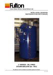
'J' SERIES - GAS FIRED
STEAM BOILERS (6J - 60J)
This Manual must be available to the boiler operator at all times.
JGAS-E-10 2008
In case of Emergency
This boiler has been designed and constructed to meet all of the essential requirements of the applicable
European Directives and subject to proper maintenance should not give occasion to any hazardous
conditions. If such a condition should occur during commissioning or during subsequent operation of
this product, what so ever the cause, then the fuel supply to the boiler should be isolated immediately,
until such time that the fault has been investigated by a competent person and rectified.
For Your Safety!
The following WARNINGS, CAUTIONS and NOTES appear in various sections of this manual.
It is the responsibility and duty of all personnel involved in
the operation and maintenance of this equipment to
fully understand the WARNINGS, CAUTIONS and
NOTES by which hazards are to be eliminated or
reduced.
Personnel must become familiar with all aspects of
safety and equipment prior to operation or
maintenance of the equipment.
WARNINGS must be observed to prevent
serious injury or death to personnel.
CAUTIONS must be observed to prevent
damage or destruction of equipment or
loss of operating effectiveness.
NOTES must be observed for essential
and effective operating procedures,
conditions and as a statement to be
highlighted.
WARNING
Steam Boilers are a potential hazard, possibly
fatal if not properly maintained.
CAUTION
It is vitally important that the instructions given
in this manual are strictly adhered to.
Failure to carry out the routine maintenance checks could result
in a drastic reduction in the life expectancy of the boiler.
The Pressure System Safety Regulations 2000
Fulton Boilers fall within the scope of the Pressure Systems Examination Scheme.
Regular inspections are therefore required by a 'Competent Person'.
The scope of the examination and the actual intervals between examinations is at the discretion of the competent person.
It is the responsibility of the user to provide a written scheme of examination for those parts of the system in
which a defect may give rise to danger.
Instructions in this manual are provided for the safe operation and maintenance of the boiler and do not cover
periodic statutory inspections.
For further information contact:
(a)
SAFed
SAFETY ASSESSMENT FEDERATION Limited.
Nutmeg House,
60 Gainsford Street,
Butlers Wharf,
London, SE1 2NY.
(b)
Health and Safety Executive local office.
(c)
Your Competent Person.
J Gas 08 2008
LIST OF CONTENTS
TITLE
INTRODUCTION
General
Technical Data (for a full specification refer to section 5)
INSTALLATION
General
Siting
Ventilation
Flue Outlet
Water Supply (see also Water Treatment in section 5)
Blowdown Valves
Main Steam Valve
Steam Safety valves
Water Gauge Set
Gas Supply
Gas Valve, Pilot Gas (40 - 60 models & Australia)
Electrical Requirements
Steam Pressure Gauge
Commissioning the Boiler
Boiler Inspection and Initial Firing
Setting the Burner Controls for Low Fire/High Fire, Models 40-60
Multibloc Gas Valves
Cleaning Steam Lines and Pressure Vessel
Gas Supply - Propane/Butane
OPERATION
General
Boiler Controls
Control Panel - Indicator Lights
Filling the Boiler - All Models
Starting the Burner - All Models
Daily Operating Tests
Pump Check
First Low Water Level Check
Second Low Water Check Blowdown Procedures
Evaporation Checks
Troubleshooting - Boiler
Troubleshooting - Burner Control Unit LFL - 1
Troubleshooting - Burner Control Unit TMG 740-3
Draining the Boiler
Long Term Shut Down
SECTION
1
1.1
1.2
2
2.1
2.2
2.3
2.4
2.5
2.6
2.7
2.8
2.9
2.10
2.10.1
2.11
2.12
2.16
2.16.1
2.16.2
2.17
2.18
2.19
3
3.1
3.2
3.3
3.4
3.5
3.6
3.6.1
3.6.4
3.6.5
3.7
3.8
3.9
3.10
3.11
3.12
3.13
Maintenance Log
MAINTENANCE
General
Daily
Weekly
Monthly
Three Monthly Six Monthly
4
4.1
4.2
4.3
4.4
4.5
4.6
GENERAL DATA
Boiler Dimensions
Boiler Specification
Recommended Water Conditions
Probe Lengths
Wiring Diagrams
Pressure Controller
Boiler Controls Test Log
5
J Gas 08 2008
SAFETY
The instructions provided for the operation and maintenance of the boiler MUST be observed.
Failure to do so could result in damage to the boiler and serious personal injury.
WARNING
It is the responsibility of the installer to ensure all parts supplied
with the boiler are fitted in a correct and safe manner.
WARNING
Do not try to do repairs or any other maintenance
work you do not understand. Obtain a Service Manual from
Fulton or call a Fulton Service
Engineer
WARNING
Understand the electrical circuit before connecting or disconnecting an electrical component. A wrong connection can
cause injury and or damage.
WARNING
Do not change the boiler fuel without consulting the boiler
manufacturer.
WARNING
Non-approved modifications can cause injury and damage.
Contact your Fulton dealer before modifying the boiler.
WARNING
WARNING
A defective boiler can injure you or others. Do not operate
a boiler which is defective or has missing parts. Make sure
that all maintenance procedures are completed before using the boiler.
WARNING
The installation of Gas appliances including the flue system
should only be carried out by Corgi
Registered Enginee
WARNING
The importance of correct boiler water and feed water cannot be over emphasised, see the relevant section in this
manual.
WARNING
DANGER FROM INCOMPLETE COMBUSTION
The importance of correct burner adjustment to achive low
emissions, safe, clean and efficient combustion is paramount.
Poor combustion, where unburnt gas forms carbon monoxide
is both a health hazard, and the potential risk to the boiler
from overheating, caused by re-burning of the unburnt gas
in the secondary flue passes.
CAUTION
Obey all laws and local regulations which affect you and
your boiler.
CAUTION
WARNING
Only qualified persons should be allowed to
operate and maintain the boiler and its equipment. Boilers
should always be drained through an approved Blowdown
Vessel.
LOW FEED WATER TEMPERATURE
Low feed water temperature can result in thermal shock to
the boiler pressure vessel. Return the maximum amount of
condensate and if necessary pre-heat the feed water. If in
doubt consult FBW.
LIFTING EQUIPMENT
Make sure that lifting equipment complies with all local regulations and is suitable for the jobYou can be injured if you
use faulty lifting equipment. Make sure the lifting equipment
is in good condition.
WARNING
Operating the boiler beyond its design limits can
damage the boiler, it can also be dangerous.
Do not operate the boiler outside its limits.
Do not try to up grade the boiler performance by unapproved
modifications.
WARNING
DANGER FROM HOT SURFACES
Steam Boilers have high temperature surfaces, that if touched
may cause serious burns. Only
competent and qualified personnel should work on or in the
locality of a steam boiler and ancillary equipment. Always
ensure the working area and floor are clear of potential
hazards, work slowly and methodically.
Do NOT store inflammable materials near the boiler.
CAUTION
HYDRAULIC TEST - RISK OF BRITTLE FRACTURE
Hydraulic testing requires specialist equipment and is normally only required by engineering surveyors / inspectors.
The material the boiler is manufactured from, has not been
impact tested, as it is not a requirement of BS2790 (boiler
construction
standard). In order to ensure the material / pressure vessel
does not suffer from brittle fracture,
hydraulic testing should not be carried out
below 7OC.
CAUTION
WATER SOFTENER and CHEMICAL TREATMENT
The chemicals required to operate the water softeners and
chemical treatment plants are NOT SUPPLIED by Fulton.
It is the responsibility of the operator to ensure adequate
supplies of chemical are available at all times (including
commissioning).
Costly repairs could be required should the plant
operate without chemicals or the wrong dosage of
chemicals.
J Gas 08 2008
Optional Variations (where fitted)
Motorised High / Low Control B
Spirax High Integrity Level Controls C
Automatic TDS Blowdown System D
Title
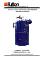
Gas Fired Steam Boiler
General Arrangement
Typical Installation
Boiler Flue Connection
Boiler Feed Water Arrangement
Boiler Blowdown (20 - 60)
Boiler Blowdown (6 - 15) Water Column Blowdown Valve
Water Column Sequencing Valve
Boiler Top Components
Steam Pressure Gauge
Burner Electrode Settings
6 - 30 Gas Valve
Pressure Controller
40 - 60 Gas Valve
Gas Valve Detail Control Panel Facias
Boiler Blowdown Valve
Sequencing Blowdown Valve
Water Level Gauges
Boiler Maintenance
Removing/replacxing UV Detector
Handhole
Boiler Furnace
Ignition Electrode
Burner Plate
Burner Assembly
Flue Cleaning
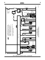
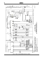
Boiler Dimensions Electrical Circuits
Three Phase Supply Circuit
Three Phase Supply Circuit - Australian Boilers Only
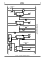
Ancillary Control Circuit
Burner Control Circuit Burner Control Circuit, Australian Boilers Only
Burner Control Circuit, High - Low Gas
PM5 Remote Panel / Typical boiler Connections
Tank Solid State Water Level and Alarm Circuits
Standard Single Boiler and
Ancillary Skid Electrical Connections
Spirax Level Control Circuit
LC Level Control Circuit
TDS and Blowdown Control Circuit
J Gas 08 2008
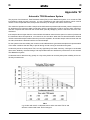
Appendix
Fig. No.
1
2
3
4
5
6
7
8
8A
9
10
11
12
13
14
15
16
17
18
19
20
21
22
23
24
25
26
27
28
29
30
31
32
33
34
35
36
37
38
39
40
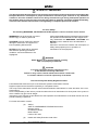
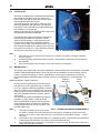
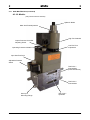
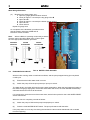
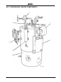
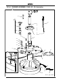
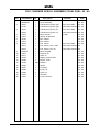
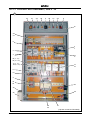
1
1
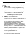
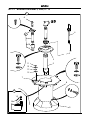
Monobloc
Gas Valve
Supply Gas,
Pressure Test Point
Steam
Pressure
Gauge
Feed Water Isolating
Ball Valve
Gas Supply Valve
Gas Inlet
Feed Water
Non-return
Valve
Scale Trap
Steam Supply
Valve
Safety Valve
Air Pressure
Switch
Water Column
containing
water level
probes
Air Intake
Manifold
containing
Main Air
Control
Sight Gauge
Blowdown
Valves
Boiler Control
Panel
Control Box
Door Lock
Water Column
Blowdown Valve
Feed Water Pump
Isolator Switch
Control Box
Isolator Switch
Boiler
Blowdown Valve
Steam Pressure
Control
Clean Out Handhole
(Water Jacket)
Clean Out Door
(Gas turn around)
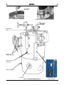
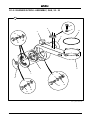
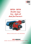
FIG.1 GAS FIRED STEAM BOILER
1
J Gas 08 2008
1
1
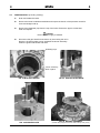
INTRODUCTION
SECTION 1
1.1 General (Fig. 1)
The J Gas Service Manual is a generic publication, as such provides information on standard boiler operation and maintenance.
The Fulton J Series Gas Fired Steam Boiler is a vertical two pass boiler of simple and efficient design and construction. Every care has been taken in the manufacture of the boiler to ensure that quality and reliability standards are maintained. However, satisfactory performance can only be ensured if the installation recommendations, operating routines and maintenance schedules laid out in this manual are adhered to.
1.2
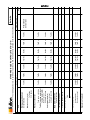
Technical Data - Boiler Output
for a full specification refer to Section 5.
BOILER MODEL
6J
8J
10J 15J 20J 30J
40J
50J 60J
Output
kg/h (F & A 100oC)
96
128 160 240 320 480
640
800 960
CAUTION
WATER SOFTENER and CHEMICAL TREATMENT
The chemicals required to operate the water softeners and chemical treatment plants are NOT SUPPLIED by Fulton.
It is the responsibility of the operator to ensure adequate supplies of chemical are available at all times (including commissioning).
Costly repairs could be required should the plant operate without chemicals
or the wrong dosage of chemicals.
J Gas 08 2008
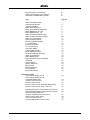
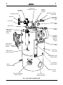
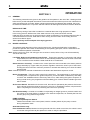
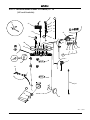
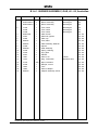
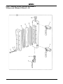
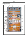
2
2
2
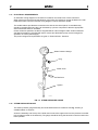
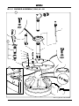
Modular
Gas Unit
Pressure
Test Point
Gas Cock
Steam Pressure Gauge
Feed Water Isolating
Ball Valve
Check Valve
Scale Trap
Main Steam
Valve
Steam Safety
Valve
Air Safety
Switch
Water
Column
with water
level probes
Blower
Housing
containing
Main Air
Control
Burner
Motor
Water
Gauge
Sets
Operator
Control
Panel
Blowdown
Valve
Water
Column
Blowdown
Valve
Pressure
Control
Main
Boiler
Blowdown
Valve
Clean Out Door
(Gas turn around)
Hand Hole
(Water Jacket)
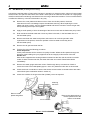
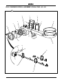
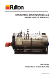
FIG. 2 GENERAL ARRANGEMENT
3
J Gas 08 2008
2
2
INSTALLATION
SECTION 2
2.1
GENERAL
The installation of a J Series Gas Fired Steam Boiler should be carried out by competent personnel in accordance with all relevant safety regulations. It is the responsibility of the installer to ensure that these regulations are complied with.
The requirements and instructions contained in this Section generally relate to the boilers being
installed to operate on natural or manufactured gas. Where the boiler is to operate on L.P. Gas,
special reference should be made to Section 2.10 - Gas Supply, and Section 2.18 L.P. Gas Supply.
2.2
Siting ( Reference should be made to Utilization Procedures as stated in IGE/UP/10 Part 1
Communication 1676, and in particular to Section 5, Location of Appliances ).
The boiler house should be sufficiently large to allow easy and safe access to all parts of the boiler for operational and maintenance purposes.
Reference should be made to Section 5 - General Data to ascertain the relevant dimensions and weights, special note should be taken of the required vertical clearance required for maintenance.
WARNING
Maintenance on the burner assembly requires the area directly above
and to one side of the boiler must not be obstructed with pipework or
equipment which would interfere with the removal of the complete burner
unit. Care should be taken on installation of the boiler to ensure this
area remains clear of obstructions.
The flooring must be level, laid in a non-combustible material and be of sufficient strength to support the boiler.
2.3
Ventilation
Adequate fresh, clean air is necessary for safe and efficient combustion, and should be provided at high and low level in accordance with BS 6644 1991 and IGE/UP/10 Part 1 Communication 1676.
Note:
(a) Ensure there is adequate ventilation in the boiler room. Lack of ventilation will create a high temperature and cause control lockout.
(b)
Do not keep exhaust fans running with windows, doors and vents closed, this will interfere with the necessary boiler draught.
(c)
Do not store chemicals such as perclorethylene in the boiler house, the fumes may
damage the boiler and flue and cause the burner to lock out on flame failure.
Note: see section 5 for Low and High Level values.
J Gas 08 2008
4
5
Water column
blowdown line
Steam Supply
J Gas 08 2008
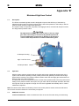
FIG. 3 TYPICAL INSTALLATION
Boiler blowdown valve
Flanged connection
20 - 60J only
Flue spigot
Strainer
D
H = 1.5 X D
D = Diameter of flue
Flue
H
Plugged drains
Stainless steel
feed water and
condensate
return tank
F03164
Drain
Overflow to
drain
Blowdown
Separator
Vent
Make-up feed water supply
Note: A break tank may be required depending
upon Local Water Authority By-laws
Isolating gate/ball valve
Flexible link
Overflow
Standard boiler trim
supplied with boiler
Condensate return
Feed water
pump
Clean-out door
Draught stabiliser
(when fitted)
Feed water non-return valve
Feed water isolation ball valve
Pipe safety valve
to a safe area,
using unions and
drain as required.
Cowl
2
2
2
2
2.4
Flue Outlet
The boiler is supplied with a stainless steel flue spigot that should be inserted into the flue outlet in the back of the boiler and secured with the three angle clips supplied loose in the trim box.
The height and type of flue will be subject to local planning regulations and approvals. The following
information is only intended to provide assistance for the installation of a simple flue.
Where multi-boiler flues or difficulties are experienced,
specialist advice should be obtained.
The flue diameter must be the same or larger than the flue flange provided with the boiler and the outlet should be at least 1 meter higher than the
nearest ridge to avoid down draughts. Where a
chimney cowl is fitted, care should be taken to ensure that the distance between the lowest point of the cowl and the top of the flue is 1.5 X the diameter of the flue.
and that it is of the terminal cone type.
FIG. 4 BOILER FLUE CONNECTION
Note:
1.
2.
3.
2.5
If the flue layout is such that it may produce an excessive up-draught, a draught stabiliser
may be required.
Avoid fitting 90deg. elbows whenever possible, if unavoidable compensate by increasing the flue diameter.
Ensure all flue pipes from the boiler to the main flue have a rising pitch.
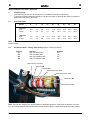
Water Supply
The quality of the water used in the boiler will affect the life and performance of the boiler. Feed water contains solids and dissolved gases, these may promote encrustations of scale; foaming, priming, surging; corrosion and pitting; or caustic embrittlement. To prevent this happening it is strongly
recommended that a reputable water treatment concern is consulted prior to commissioning the boiler.
Isolating
Check
Note: see Section 5 Water Treatment.
Ball Valve
Valve
Connect the feed water pump to the check valve inlet with 25 mm. bore pipe (this may be reduced to 15 mm. where the discharge pipework is shorter than 4m in total), the pump suction pipe work must remain at 25mm minimum diameter.) and insert the stop valve supplied, between the boiler and the check valve.
It is essential to protect the feedwater pump from Feed
damage by foreign matter, a strainer should
Water
therefore be fitted in the pump suction pipework
Supply
Care should be taken to ensure the pipework is properly aligned and not placing any strain upon the feed water pump.
Note: FIG. 5 BOILER FEED WATER ARRANGEMENT
1.
The boiler feedwater pump may contain an inhibitor and this should be flushed from the pump prior to fitting the pump to the boiler. Failure to do so may result in water bounce or foaming due to the inhibitor forming a seal in the boiler.
2.
If the boiler is to be operated with little or no condensate return, consideration should be given
to pre-heating the feedwater. If in doubt consult Fulton Boiler Works.
3.
The Feedwater inlet connection on some boilers is located on the left hand side of the boiler below the sight glass assembly.
J Gas 08 2008
6
2
2
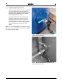
2.6
BOILER Blowdown Valves
There are three blowdown valves on the boiler
(four if two water gauge sets are fitted), the boiler blowdown valve at the rear of the boiler, the water column blowdown valve and the
water gauge blowdown valve.
All of these valves must be connected to a blowdown receptacle of approved design.
Regulations exist covering such items and care must be taken to ensure compliance with these regulations. If in doubt regarding blow
down arrangements, consult your Fulton agent.
Note: 6J - 15J main blowdown connection via branch
pipe 20J - 60J main blowdown connection is integral,
via a boiler mounted flange.
FIG. 6 BOILER BLOWDOWN (models 20-60)
(skid mounted boiler shown)
FIG. 7 BOILER BLOWDOWN (models 6 - 15)
(skid mounted boiler shown)
7
J Gas 08 2008
2
2
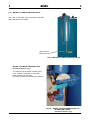
2.6.1 WATER COLUMN Blowdown Valve
The valve on the water column should be operated
daily to blowdown the column.
Water Column
Blowdown Valve
FIG. 8 WATER COLUMN BLOWDOWN VALVE
WATER COLUMN Blowdown Valve
(Australian boilers only).
The valve is a three position isolation valve, each position is indicated on a backing
plate mounted with the valve,
(the valve is shown in the blowdown position).
FIG. 8A
J Gas 08 2008
WATER COLUMN SEQUENCING and BLOWDOWN VALVES
(Australian boilers only)
8
2
2
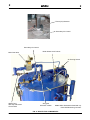
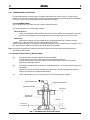
Flame (UV) Detector
Secondary Air Control
Secondary Air Control
Main Gas Valve
Boiler Water Level Probes
Air Proving Switch
Water Feed
with Stop Valve and
Check Valve
Gas Train
with 360O rotation
Note: Boiler illustrated is fitted with optional Self Monitoring Controls.
FIG. 9 BOILER TOP COMPONENTS
9
J Gas 08 2008
2
2.7
2
Main Steam Valve
The main steam stop valve should be inserted in the steam line approximately 12in. (305 mm) from the
top of the boiler.
2.8
Steam Safety valves
Safety Valves are factory fitted and preset, they MUST NOT be adjusted. The discharge outlet should be piped to a safe discharge point and the piping so arranged that any condensate trapped in the pipework will drain away from the valve.
Note: It is recommended that the safety valve discharge pipework is installed to the requirements of
BS806 clause 4.9.7. / BSEN 134801-1:2002
(a)
(b)
(c)
The lift pressure is indicated on the safety valve. (Do not adjust).
The safety valve fitted to the boiler is designed to prevent the boiler exceeding it's design pressure.
Any system connected to the boiler not capable of accepting boiler pressure must be protected by a separate safety valve set to the required pressure.
WARNING
Factory fitted safety valves are preset to protect the boiler only and
must not be used to protect any other items not capable of
accepting boiler pressure.
2.9
Water Gauge Set (The design may vary from that illustrated)
Numbers may vary due to individual countries regulations.
Boilers are normally supplied with two complete water gauge sets.The water gauge blowdown cock should be connected to the auxiliary blowdown line from the water column blowdown valve in soft copper tubing. The connection to the gauge cock is DN8, 6mm (1/4in. BSP).
2.10 Gas Supply
Verify that the burner is suitable for the type of gas being supplied. Ensure the piping from the meter is the correct size, and that a gas cock is inserted in the line between the boiler and the meter. To avoid pressure drops, eliminate all unnecessary bends and elbows in the pipework between the gas meter and the boiler. A scale trap is provided on the gas train and should be used.
Burners suitable for operation on natural and manufactured gas are supplied with gas trains or a modular gas head which are fitted with pressure regulating governors. A minimum pressure of 7 in.
(17.5 mb) water column at the specified flow rate, is required at the gas train for natural gas installations and a minimum pressure of 5 in. (12.5 mb) water column is required at the gas train for manufactured gas installations.
If the gas supply is in excess of 100 mbar (6 - 30) or 200 mbar (40 - 60) a suitable regulator is required before the main gas valve.
Burners arranged for operation on L.P. gas are supplied with gas trains which include a pressure regulating governor. It is essential that the MAXIMUM pressure of the gas at the gas train does not exceed 32 in. (80 mb) water column and does not fall below 20 in. (50 mb) water column. To obtain these pressures a pressure regulating device or service governor must be fitted to the supply line from the storage tank to the boiler gas train.
Careful consideration must be given to the siting of LPG storage tanks to prevent over pressure conditions arising, due to temperature rises caused by solar gain.
2.10.1 GAS VALVE, with pilot gas line.
(Models 40 - 60 and Australian boilers).
The main gas valve is fitted with a by-pass system (internal or external depending on the model)
the by-pass allows pilot pressure to be maintaned whilst the flame is verified.
J Gas 08 2008
10
2
2
2.11 Electrical Requirements
An individual wiring diagram for the boiler is located on the inside cover of the control box.
When referring to the electrical specification of the boiler, the reference number located on the rear inside wall of the control box and the wiring diagram number should be quoted.
The audible alarms provided are mounted on the side of the control panel, if not audible they should be repositioned where they can be heard by a person competent to take the appropriate action should the alarm be activated.
Unless otherwise specified, the alarms supplied will be mains voltage models. Unless otherwise specified all models are supplied with burner motors and feed water pump motors arranged for operation on a three phase supply.
The power ratings and requirements are given in Technical Data - Section 5.
Steam Pressure Gauge
Plug
Steam Cock
Test Point
Syphon
F03210
FIG. 10 STEAM PRESSURE GAUGE
2.12 Steam Pressure Gauge
The steam pressure gauge assembly should be assembled in accordance with Fig. 10 using a suitable sealant on all joints.
Screw the assembly into the top of the boiler and connect the copper tube from the pressure controller
to the nipple provided on the assembly. The gauge should be facing the electrical control box and/or the
boiler operator.
11
J Gas 08 2008
2
2
2.16 Commissioning the Boiler
It is essential that the commissioning procedures listed below are carried out by a Fulton Service
Engineer who will have the necessary experience and testing equipment to ensure that the installation
is not only correct, but is operating safely and at optimum efficiency.
FLUE COMMISSIONING
Prior to initial firing of the boiler, the flue must be checked for leaks.
This is done by BOTH of the following methods:
Visual Inspection
Check joints between all flue sections for quality of seals. Where the flue passes through the structure of the building use your judgement as to the integrity of this section of the flue.
Smoke Test
With the flue capped, the drain stabilizer pipe (if fitted) blanked and a smoke generator inserted into the flue, there should be no smoke visible from the flue.
If either of these tests fail or at any time during boiler operation, there is doubt about the integrity of the flue, shut down the boiler and contact Fulton Boiler Works Immediately.
Note: Flues that are designed to operate with positive pressure should be tested to the requirements
of IGE/UP/10 March 2001.
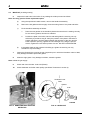
2.16.1BOILER INSPECTION and INITIAL FIRING
(a)
Ensure the boiler has been washed out after installation.
It is advisable to conduct a water analysis before operating the boiler.
Examine the probes in the water column and the boiler shell and record their lengths.
Replace any damaged probes.
(b) If the burner is fitted with an ultraviolet or solid state detector, remove the detector and check for damage.
Remove the burner and check that the electrodes have not been damaged and that their
setting corresponds to the appropriate drawing.
Check that the burner is the correct type for use with the gas being supplied.
(c) Main Gas Supply
Ultra-Violet Detector
Ignition Electrode
297.4mm
Primary Air
Blast Tube
12.7mm
3 mm min.
5 mm max.
50.8mm
FIG. 11 BURNER ELECTRODE SETTINGS
J Gas 08 2008
12
2
2
Main Gas Valve
Air Pressure Gauge
Feed Water
Check Valve
Safety Valve
Flue
FIG. 12 6 - 30J MODELS GAS VALVE
(d) (e) A barometric type draught stabiliser, if fitted in the flue, should be set for a draught of - 0.01 in.
to
- 0.02 in. (- 0.025 mb to - 0.05 mb) of water column pressure with the burner off.
(f)
Open all the valves in the feed water line.
Ensure that all wiring connections are correct and that all terminal screws are tight.
Close the isolating valve on the discharge side of the feed water pump. Remove the priming plug
from the pump head and slowly fill the pump with water. Replace the priming plug and tighten
secuerly.
Note the correct rotation of the pump on the motor fan cover.
Start the pump and check the direction of rotation.
Vent the pump by means of the vent valve in the pump head. At the same time, open the discharge
isolating valve a little. Continue to vent the pump. At the same time, open the discharge isolating
valve a little more. Close the vent valve when a steady stream of water runs out of it.
Completly open the discharge isolating valve.
The bypass valve located in the drain plug may be opened during the filling procedure, close the
bypass when the operation is stable.
DO NOT ALLOW THE PUMP TO RUN DRY.
13
J Gas 08 2008
2
2
(g) Open all the valves in the water feed line.
Switch on the feedwater pump motor and fill the boiler.
The operation of the pump controls should be checked by using the boiler blowdown valve (located
at the rear of the boiler). When the water sight level gauge is reading two thirds full, the pump will
stop.
Open the boiler blowdown valve and slowly drain the boiler. When the water level falls below the
pump on probe, the pump should start. If the pump does not start check the probe connections.
Close the boiler blowdown valve.
For models 40 - 60 with an external pilot gas line, see 2.16.2.
(h) After purging the gas lines of air, start the burner.
Note: For Australian boilers only:
Prove the pilot flame by placing the PILOT HOLD / NORMAL switch into the Pilot Hold position,
this will hold the gas valve in the pilot gas position until the pilot flame has been verified.
(j)
Check the Satronic burner control for a minimum of four indicator lights to verify the flame.
Adjust the gas input by reading the gas meter (if fitted).
(k)
Adjust the main air control gate located on the burner scroll, to obtain a clean combustion.
Measure the levels of CO2 CO and O2 in the exhaust gas, record the results.
See typical combustion values in section 5.
(l) Observe the flame through the peephole between the electrodes and adjust the scondary air
control located on the top of the boiler, so that the flame cannot be seen 'backing up' the blast
tube.
(m) Check the operation of the low water safety controls.
(n) If the pressure control is fitted with a differential scale:
(see OEM literature in section 5)
Adjust the steam pressure control to suit the boiler application. It should be borne in mind that
boilers are designed to operate most efficiently at their maximum operating pressure. When boilers are to be operated below a pressure of 80 psi (5.5 bar) consideration should be given to the
fitting of a pressure reducing set.
(i) Set the main scale pressure to the maximum
pressure required (system pressure).
Do not exceed the boiler operating pressure.
(ii) Set the differential scale to it's minimum pressure.
If the pressure control has a fixed differential,
i.e. no adjustable differential scale, set the main
scale to the maximum pressure required.
Note: When multiple boilers are fitted with a
sequence control:
(i)
Set the main scale and differential scale
as above.
FIG. 13
J Gas 08 2008
PRESSURE CONTROLLER
14
2
2
Main Gas Valve Assembly
Main Gas Line Isolating
Pilot Line Ball Valve
Pilot Line Governor
Pilot Line Gas Valves
Note: Australian Models are fitted
with a Gas Valve Closed Indicator
on the Main Gas Valve
FIG. 14 40 - 60J MODELS GAS VALVE
15
J Gas 08 2008
2
2
(ii)
Set the setback pressure control to the
required set back pressure.
2.16.2 SETTING THE BURNER CONTROLS FOR LOW FIRE / HIGH FIRE, MODELS 40 - 60
The correct setting for low fire/high fire operation are made by making adjustments to the two stage
solenoid
valve and the low fire steam pressure switch.
(a)
Isolate the main gas valve by closing the valve in the gas input line.
(b)
Screw the pilot gas governor fully down, (governor open).
(c)
Start the burner and where possible meter the pilot gas rate, (ideally the pilot gas rate should be
10% of the full gas rate).
(d)
Check the LED display on the Satronic control box (where fitted).
The pilot should produce a solid line of five illuminated LED's (four minimum).
Check the ignition and pilot stability several times.
Record the pilot gas pressure.
(e) Open the main gas isolating valve.
(f)
Set the gas input to the boiler for correct input on high fire. This adjustment should be done
where possible by using the gas meter.
Adjust the main and secondary air gates to obtain optimum combustion conditions.
(g)
Adjust the low fire steam pressure switch to cut-out at approximately 5 psi below the setting of
the main steam pressure control.
(h)
Adjust the two-stage solenoid valve to obtain a low fire gas input of approximately 80% of high
fire.
Leave the air gates adjustments as for high fire.
J Gas 08 2008
16
2
2
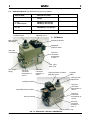
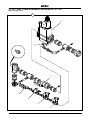
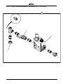
2.17 GAS MULTIBLOCS (see attached manufacturers leaflets).
BOILER SIZE
MULTIBLOC USED
6 - 30
6 - 30 Australian
MB-D(LE) 405-412 B01
MB-D(LE) 405-412 B07
40 - 60
MB-ZRD(LE) 415-420 B01
L.P.G.
Dungs:
MB-ZRD(LE) 405-412 BO1
Output pressure controller
adjusting screw
Hydraulic brake
6 - 30 Models
Main gas flow
adjustment
Operating indicator
Adjustable
pressure switch
Test point
connection
Test point
connection
downstream
of valve 1
Gas input
filter cover
Gas output
flange
Test point
connection
downstream of
valve 2
Test point
connection
upstream of
valve 1
Output pressure controller
adjusting screw
Hydraulic
brake
Main gas flow
adjustment
Operating indicator
Test point
connection
downstream of
valve 1
Adjustable pressure switch
Test point
connection
downstream of
valve 2
Gas input flange
Test point
connection
upstream of
valve 1
Gas input filter cover
FIG. 15 GAS VALVE - MAJOR COMPONENTS
17
J Gas 08 2008
2
2
2.17 GAS MULTIBLOCS (continued)
40 - 60 Models
(with pilot line fitted for Australia)
Hydraulic Brake
Main Gas Flow Adjustment
High Fire Solenoid
Output Pressure Controller
Adjusting Screw
Low Fire Flow
Adjustment
Operating Pressure Indicators
Input Gas Test Point
Adjustable Pressure
Switch
Test Point 1
Downstream
(internal leak test)
Test Point 2
Downstream
Test Point 1
Upstream
Gas Input
Mounting Flange
J Gas 08 2008
18
2
2
2.18 CLEANING STEAM LINES AND PRESSURE VESSEL
During the first week of boiler operation, clean all oil and dirt from the boiler, steam line and
condensate return line.
(a)
Disconnect the condensate return pipe adjacent to the condensate return tank.
(b)
Direct the returns to a floor drain or other safe discharge point and make safe.
(c)
Leave in this position for one week to allow all impurities to flush through.
(d)
Drain the boiler completely each day.
(e)
After the week is completed, drain and flush the condensate return tank, removing all installation sediment. Reconnect the condensate return pipe to the condensate return tank.
L.P. GAS
2.19 GAS SUPPLY - PROPANE / BUTANE
WARNING
Do not change the boiler fuel without
consulting the boiler manufacturer.
Note: LPG Boilers should be installed to the requirements of IGE/UP/10 March 2001
For PROPANE:-The boiler governor must be adjusted to give a firing pressure of 10 in. (25 mb) water column at the test point provided at the elbow on the gas train.
For BUTANE:-The boiler governor must be adjusted to give a firing pressure of 8 in. (20 mb) water column at the test point provided at the elbow on the gas train.
Gas Pressure Alarm Indicator Light
For L.P.G. applications the inlet pressure switch is used to protect the system from over pressure and should be set at 100 mbar.
19
An L.P. gas boiler is similar in design to a natural gas boiler, the main differences are important and must be taken into account when installing the boiler and ordering spare parts.
When installing an L.P. gas boiler, the feed from the bulk tank supply must be fitted with a supply governor which is set to reduce the supply feed pressure to the boiler governor to 30 in. (80 mbar) Water Column or less.
J Gas 08 2008
3
3
SECTION 3
OPERATION
3.1
GENERAL
DRYING OUT TIME
The refractory casing of the boiler is made from a material that uses a high proportion of water in the mixing process. Whilst some of the water is driven off by chemical reaction and the
initial test firing, the refractory is still 'wet' when the boiler is delivered. For a few days after the boiler is commissioned and in service, water will be seen running from the bottom of the casing and from around some branch pipes.
This is perfectly normal and part of the drying process. 3.2
BOILER CONTROLS
The following instructions are given for the guidance of the operator in the use of the J Series gas fired boiler and to provide adequate information to ensure that when the boiler is put into use it will be done safely and without risk to health. Where original equipment Service Manuals are supplied, they must be read and understood in conjunction with this manual. All Warnings and Cautions must be observed.
The following brief description of the controls used on the J Series gas fired boiler is intended to
provide the operator with a basic understanding of the operating principles, which is essential for the continued efficient operation of the boiler.
Note:All the controls are of the ‘fail-safe’ type and are wired in series; failure of any one will automatically shut down the boiler.
Low Water Relays and Feedwater Pump Relays. These relays operate in conjunction with probes
suspended in the boiler and water column to automatically maintain the level of water in the boiler
and to cut-off the burner should the water level fall to an unsafe level.
Steam Pressure Control(s). Located on the control panel box and connected to the steam pressure
gauge assembly by copper tube, the pressure regulator controls the on/off cycle of the burner,
shutting the burner off when maximum pressure is reached and switching it on when the steam
pressure falls.
Note: A set-back pressure controller is fitted when multi-boilers are fitted with a sequence control.
Burner Programmer. This is the main control in the panel box. The programmer in conjunction with
a sensing device ‘supervises’ the ignition sequence, proves the flame is satisfactory and finally
‘monitors’ the established flame. Should any fault occur, either during the ignition sequence or
during normal running, the programmer will immediately go to ‘lockout’ and the multibloc gas valve
will be closed.
Air Pressure Switch. Mounted on the burner scroll, this switch is operated by the pressure of air entering the burner through the throat of the scroll. Lack of air, or insufficient pressure, will prevent the
switch completing the circuit thus preventing the burner from operating.
Gas Head Assembly. Consists of a multibloc incorporating an integral governor, pressure switch and
gas valves or for larger boilers in addition to the internal components, an external pilot line with
it's own gas proving valves and governor.
PUMP CONTROL
Pump Interrupt/Pump Run Switch.
Fitted on the left side of the control panel, used to override (switch off) the pump controls during evaporation tests.
Australian Boilers only.
Pilot Hold/Normal switch, Mounted on the right hand side of the boiler control box, the switch is used
to hold the main gas valve at pilot pressure in order to verify the pilot flame.
J Gas 08 2008
20
3
3
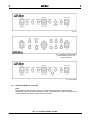
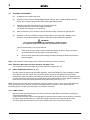
6J - 30J
40J - 60J Standard and Australian
(standard boilers have the CPI
indicator blanked)
6J - 30J Australia
3.2
BOILER CONTROLS continued.
Note:
Boilers fitted on skid units and in plant rooms are interlocked with the feed water and
condensate return tank, after switching the boiler on at the boiler control box isolator switch,
the reset button on the tank control box must be reset.
FIG. 16 CONTROL PANEL FACIAS
21
J Gas 08 2008
3
3
3.3
INDICATOR LIGHTS
Indicator lights are fitted to the control panel as an additional aid to the operator. The meaning and operating sequence of these lights is as follows:
CAUTION
The control circuit live light is dirived from a single phase. It is possible that with the control phase
down or a defective bulb the other phases could be live. Always isolate the supply before investigating any fault.
Start/Low Water Reset. This switch is used to start the boiler and to reset the low water alarm. When the switch is pressed to initiate the start-up sequence, the low water alarm lamp also illuminates and the low water audible alarm sounds. Keeping the switch depressed for approximately 2 seconds
cancels the low water alarm and initiates the burner start sequence.
Illumination of this switch and sounding of the audible alarm at any other time other than at switch on indicates that the boiler has gone to a lock-out due to a low water condition. Once the water in the boiler has been restored to a safe operating level, pressing the switch will reset the controls.
Circuit On. (Circuit Energised 40J - 60J) Indicates that power is being supplied to the control panel box.
Low Water Alarm (1st. low water). This light will energise, when the boiler is switched on and the
water level is between 1st. low water and 2nd. low water. A light will illuminate and a pulsing alarm sound.
Low Water Reset (2nd low water). The 1st. low water light and alarm are replaced by the 2nd. low
water light and a continuous alarm, indicated by the low water reset switch. The second alarm must be reset, the first alarm will be automatically reset by the return to normal water level.
Ignition. Indicates that the ignition transformer has been energised. This light will only be illuminated for approximately 5 - 10 seconds during the ignition sequence.
Gas Pressure Alarm. This light will illuminate whenever the gas is off, or below minimum inlet
pressure required by the European Standard for gas burners EN676.
This switch is factory set and should not be adjusted after the boiler has been commissioned.
Start Gas. (40 - 60 models and Australian boilers)
This light indicates the gas valves in the pilot line are energised. Flame Failure / Reset. This switch will be illuminated when the burner has gone to a lock out
condition due to flame failure. The burner controller can be reset by pressing this switch.
Combustion Air. This light indicates that the burner motor contactor is energised.
Closed Position Indicator (C.P.I.). (Australian Boilers Only)
The lamp illuminates when the gas valve is in the closed (no gas) position.
ADDITIONAL INDICATOR LIGHTS ON MODELS 40J AND 60J
Low Flame.
This light indicates that the burner is operating in the low flame mode.
High Flame.
This light indicates that the burner is operating in the full firing mode.
Main Gas. This light illuminates when the Multibloc gas valve is energised.
J Gas 08 2008
22
3
3
3.4
FILLING the boiler - All Models
Carry out the following procedure on the initial start up of the boiler and on every subsequent occasion when restarting the boiler after a shut down:
(a)
Ensure the main steam stop valve is OPEN.
(b) Ensure the steam pressure gauge isolating valve is OPEN.
(c) Ensure all the valves in the main gas supply to the boiler are OPEN.
(d) Ensure all the valves in the water feed line are OPEN.
(e)
Ensure the main boiler blowdown valve is CLOSED.
(f) Ensure water level gauge isolating valve(s) is OPEN.
(g)
(h)
Ensure water level gauge blowdown valve(s) is CLOSED.
(i)
Ensure the Burner and Pump switch is in the OFF position.
(j)
Ensure all appropriate electrical isolators are switched ON.
(k)
Ensure the pump interrupt switch is switched OFF (Pump Run).
Ensure water column blowdown valve is CLOSED.
CAUTION
The feed pump seals are water cooled.
The pump must never be allowed to run whilst dry, irreparable damage may result.
Ensure the pump is fully primed before energising the motor.
(l)
Press the control switch to the PUMP ONLY position.
Note: If the boiler water level is below its correct level, the feed water pump will operate. When the water reaches the correct level (two thirds up the water level gauge sight glass), the pump will stop. If the water level is above the top of the water level gauge sight glass, drain off until the level is in the middle of the water level gauge sight glass.
23
J Gas 08 2008
3
3
3.5
STARTING THE BURNER
(a)
CLOSE the main steam stop valve.
(b)
Press the control switch to 'PUMP AND BOILER' position, the low water audible alarm will sound, the low water reset and low water alarm lights will illuminate.
(c)
Press the low water reset switch for two seconds maximum.
The alarms will stop, and the alarm lights extinguish.
The burner start sequence will commence.
After a maximum of one minute the burner should be firing, and the main gas light ON.
(d) (e)
When the boiler has achived the required (set) pressure, the main steam isolating valve
should be slowly opened allowing steam to enter the system distribution pipework.
WARNING
The system should be raised to temperature slowly to allow
for expansion and to avoid thermal shock and water hammer.
This can be achived by one of two methods.
1.
2.
Crack open the main steam valve and allow the system to heat up slowly, (minimum
15 minuets) before fully opening the main steam valve.
Open the main steam valve when starting the boiler, allowing the boiler and system to heat up together.
Note: This can lead to water logging of the steam lines until full pressure is achived.
Note: TDS Panel Mounted Controllers (BC3210 - BC3200) if fitted.
The controller must be reset after any break in electrical supply to the unit.
3.6
Daily OPERATING TESTS (3.6 - 3.7)
Visually inspect the steam and feed water pipework, valves and fittings for signs of leakage. If leaks are suspected shut the system down and evacuate the system to atmospheric pressure before
attempting to repair the leaks. The following procedure should be carried out by a competent person to ensure the correct functioning of the water level and low water safety controls. Where possible, the boiler should not be under steam pressure during these tests, (see 3.6.5.g.2.).
Note: Ensure that the water level is maintained during the pressure build up. If any part of the equipment is not operating correctly, the fault should be investigated before the boiler is used. Ensure that all blowdown pipework is safe and discharged to a blowdown receptacle.
3.6.1. Pump check
With the burner firing and the pump not running, lower the water level in the boiler by opening the main boiler blowdown valve.
As the water level falls, visible in the sight glass, and before the low water lock out position is reached the water pump should start to run. When this happens close the main boiler blowdown valve.
The water pump should continue to run and re-fill the boiler to the correct level and stop.
J Gas 08 2008
24
3
3
3.6.4 First Low Water Level
(a)
Ensure the following:
The burner is firing.
The water level is correct in the boiler.
The water pump is not running.
(b)
Switch the pump off (Pump Interrupt) at the pump interrupt/pump run switch.
(c)
OPEN the main blowdown valve.
(d)
When the water level nears the bottom of the water level gauge sight glass, the low water alarm should sound, the LOW WATER ALARM lamp should illuminate and the burner should stop
firing. When this happens, CLOSE the blowdown valve IMMEDIATELY.
(e)
Switch the pump to RUN at the main pump interrupt/pump run switch. The pump should run and refill the boiler. When the water level in the boiler rises above the first low water level, the LOW WATER LEVEL lamp should extinguish, the audible alarm should silence and the burner start sequence should commence automatically.
The pump should run until the boiler water level is correct and then stop.
3.6.5 Overriding (2nd) Low Water Check
(a)
Ensure the following:
The burner is firing.
The water level is correct in the boiler.
The water pump is not running.
(b)
Switch the pump off (Pump Interrupt) at the pump intrrupt / pump run switch.
(c)
OPEN the main blowdown valve.
(d)
When the water level nears the bottom of the water level gauge sight glass, the LOW WATER ALARM lamp should illuminate, the low water audible alarm should sound and the burner
should stop firing.
(e)
Continue to blow down the boiler. As the water level falls nearer the bottom of the water level gauge sight glass, the LOW WATER RESET switch should illuminate and the second audible low water alarm should sound.
(f)
CLOSE the main blowdown valve and switch the pump to RUN at the pump interrupt/pump run switch. The water pump should now start to run and refill the boiler. Once filled to the correct
level the pump should stop. The low water alarm should continue to sound, the LOW WATER RESET switch and LOW WATER ALARM lamp should remain illuminated and the burner should NOT start.
(g)
When the water level in the boiler is correct, the burner can be restarted by depressing the
LOW WATER RESET switch for a maximum of 2 seconds.
1.
The First and Overriding low water checks can be carried out in one operation to reduce the blowdown time and possible interruption to the steam supply.
2.
Where the water level tests are to be carried out at full pressure, evaporate the water down to 1st. low level as in 3.8, blowdown the boiler from 1st. to 2nd. low water.
The purpose of adopting this procedure is to prevent steam and water being expelled from the blowdown vessel vent because of prolonged blowdown.
25
J Gas 08 2008
3
3
3.7
BLOWDOWN PROCEDURES (DAILY TESTS)
Keep the boiler, water gauge, water column and interconnecting pipework free from sludge and scale buildup by blowing down in the following manner:
Note: Where a boiler is operating continuously at steam pressure, advice should be sort from Fulton
regarding the appropriate blowdown procedure.
(a) Start the boiler and generate not more
than 10psi of steam.
(b) Shut off both the burner and the pump.
Boiler Blowdown
(a) Fully OPEN the boiler main blowdown
valve for not more than 10 seconds.
Water Column
(b) CLOSE the valve.
Blowdown Valve
Note: Where high levels of suspended solids are produced,
longer and/or more frequent blowdown may be required.
Water Column Blowdown
Note: The water column contains the pump
on/off probe, which is not safety interlocked.
(a) OPEN the ball valve in the water column, close after 5 seconds.
Australian Boilers only
Water Column Blowdown
1. Place the sequence valve lever into the
blowdown column position A.
A
2. Open the Column blowdown valve B for
5 seconds then CLOSE.
3. Place the sequence valve lever into the
blowdown leg position C.
4. Open the Column blowdown valve B for
5 seconds then CLOSE.
5. Return the sequene lever to the working
D
C
B
A
B/DOWN COLUMN
Operating handle shown
in the closed position.
Fig. 17 BOILER BLOWDOWN VALVE
C
B/DOWN LEG
D
WORKING
POSITION
Fig. 18 SEQUENCING BLOWDOWN VALVE
J Gas 08 2008
26
3
3
Water Gauge Blowdown
(a) Blowdown the water gauge, set 1.
1. Open the gauge glass blowdown valve A
2. Close (for approx. 3 seconds) the top gauge valve B
3. Open valve B
4. Close (for approx. 3 seconds) the bottom gauge valve C
5. Open valve C
Water Level Gauge
6. Close valve A
Set 2
Repeat for gauge set 2
On completion of the blowdown procedure ensure
that all isolation valves are OPEN and all
blowdown valves CLOSED.
B
Note: Where a Boiler is operating continuously at steam
pressure, advice should be taken from a Fulton agent
as to the appropriate blowdown procedure.
WORKING
POSITION
STEAM
BLOWDOWN
WATER
BLOWDOWN
B
B
B
C
C
A
A
C
C
A
Water Level
Gauge
A
Set 1
Water Level Gauge Operating Positions
FIG. 19 WATER LEVEL GAUGES
3.8
EVAPORATION CHECKS
With the boiler running under normal load conditions, and the pump stopped having just completed a refill cycle:
(a)
Ensure that the boiler water level is correct.
(b)
Switch the pump off at the pump interrupt / pump run switch.
If it is required to check the second low water alarm, wait a further period for the LOW WATER RESET switch to illuminate.
When the check is complete, proceed as follows:
(a)
Switch the pump to RUN at the pump interruptpump run switch.
(b)
Press the LOW WATER RESET switch. The pump will start to refill the boiler.
If the pump starts to run at any time during the test then the test must be abandoned and re-started from the beginning.
27
The water level in the boiler will lower through natural evaporation. When the level nears the bottom of the water level gauge sight glass, the first low water alarm will sound, the LOW WATER ALARM lamp will illuminate and the burner will shut down.
J Gas 08 2008
3
3
3.9
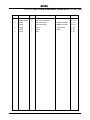
TROUBLESHOOTING
Problem Cause
Ignition Failure 1. Power Supply
2. Ignition Electrodes
3. Transformer
4. Burner Control
5. Air Settings
6. Faulty Air Switch 7. Gas Valve
8. Gas supply 9. Loose wire connections
Remedy
Check fuse or Circuit breaker.
Reset or Replace as required.
Check for cracks in porcelain,if found replace the electrode. Check electrodes for carbon build-up.
Clean as required.Check settings, adjust if
required.
Check voltage between transformer leads at
terminal block to be sure transformer is live.
Check voltage between ignition terminal and
neutral, this check must be made before the
control locks out. If no power, replace the control.
Check main air adjustment and secondary air
adjustment.
Check for faulty air switch.
Check filters in the valve block. Clean as required.
Check for gas pressure and intermittent supply
problems.
Check connections to all components.
Flame Failure 1. Power Supply Check fuse or Circuit breaker.
During Start-up Reset or Replace as required.
2. Gas supply Check for gas pressure and intermittent supply
problems.
3. Air Settings Check main air adjustment and secondary air
adjustment.
4. Ignition Electrodes Check electrodes for carbon build-up.
Clean as required. Check for proper adjustment, readjust if necessary. Check for cracks in
porcelain, if found replace the electrode.
5. UV Detector
Check the detector is located correctly and clean.
6. Burner Control Check voltage between ignition terminal and
neutral, this check must be made before the
control locks out.
If no power, replace the control.
7. Loose wire at fuel valve circuit. Tighten wiring connections.
8. Contact open on
Air Switch Adjust to the correct setting.
9. UV Detector wiring
reversed at control box. Change to the correct terminals.
Flame Failure 1. Power Supply
During Normal Run 2. Gas Supply
3. UV Detector
4. Faulty Air Switch 5. Bad Combustion Check fuse or circuit, reset or replace as
necesssary.
Check gas pressure coming into the gas train,
if low contact the gas supplier.
Check the setting on the gas valve regulator,
adjust as required.
Check the detector is located correctly and clean.
Check for faulty air switch.
Check combustion readings.
J Gas 08 2008
28
3
3
3.9
TROUBLESHOOTING, continued.
Problem Cause
Burner Cut-off 6. Gas Valve
7. Weak Amplifier
(Honeywell Control Box Only)
8. Weak Pilot
9. Faulty Level Control
10.Dirty or defective
UV detector
Remedy
Check filters in the valve block. Clean as required.
Replace the amplifier.
Adjust to larger pilot by adjusting pilot gas
pressure regulator.
Test level controls, adjust or replace as required.
Clean or replace.
Poor Combustion1.Refractory Bricks Check refractories to see if they are plugged with soot or broken in pieces. Clean or replace as
necessary.
2. Stainless Steel Ring Check the ring is present (40 - 60 models) and fits tightly against the furnace wall.
3. Main Air Adjustment Check air adjustment. Air/fuel mixture may be off. Open main air gate until the flame brushes the
furnace wall.
4. Secondary Air
Adjustment Check main air adjustment, reset as required and secure in place. Check CO2 and O2 levels.
5. Draft
Check draft with a gauge. Readings will vary
between installations, if in doubt consult Fulton
for a draft value for your system.
6. Dirty Flue Check flue for carbon build-up or blockage.
Clean the flue.
7. Negative Room Pressure Ensure there are no exhaust fans running in the
boiler room.
8. Dirty Fan Check fan for obstructions, clean as required.
Burner Back Fires 1. Refractory Bricks Check refractories to see if they are plugged with soot (Delayed Ignition) or broken in pieces.
Clean or replace as necessary.
2. Ignition Electrodes Check electrodes for carbon build-up.
Clean as required. Check for proper adjustment, readjust if necessary. Check for cracks in
porcelain, if found replace the electrode.
3. UV Detector Check the detector is located correctly and clean.
4. Draft Check draft with a gauge.
Draft should be -.05 to -.10mbar with the
burner off,
or -.10 to -.15mbar when operating.
A barometric damper may need to be installed.
5. Negative Room Pressure Ensure there are no exhaust fans running in the
boiler room.
6. Air Adjustment Check Air Adjustment settings.
7. Gas Supply Check gas pressure coming into the gas train,
if low contact the gas supplier.
Check the setting on the gas valve regulator,
adjust as required.
29
J Gas 08 2008
3
3
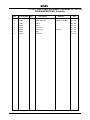
3.9
TROUBLESHOOTING, continued.
Problem Cause
Boiler will not
maintain pressure 1. Gas Supply
2. Dirty Flue 3. Pressure Control
4. Scale build-up in boiler
5. Refractory Bricks. 6. Steam traps
blowing through.
7. Boiler size.
8. Faulty Gas Valve. Boiler is Surging 1. Steam traps
(Widely fluctuating blowing through.
water level in 2. Contamination
sight glass) in boiler. 3. Scale buildup or
lime deposits.
4. Too much compound
(water treatment
over dose). in the system.
5. High Alkalinity (high ph).
6. Load exceeds
boiler capacity.
Remedy
Check gas pressure coming into the gas train,
if low contact the gas supplier.
Check the setting on the gas valve regulator,
adjust as required. If possible meter the flow rate.
Check flue for carbon build-up or blockage.
Clean the flue.
Disconnect all power to the controller.
Disconnect the wires from the controller.
Place an OHM meter between the switch
terminals. Lower the set point of the controller,
the switch should make. Raise the set point and recheck, the switch
should break. If the controller operates improperly, replace it. Clean the pressure vessel.
Check refractories to see if they are blocked
with soot or broken in pieces. Clean or replace as necessary.
Check steam traps, clean or replace as required.
Boiler may be undersized.
Check gas flow rate.
Check steam traps, clean or replace as required.
Empty boiler and feed tank.
Flush out and refill, if system operates but progressively
deteriorates, there is probably a leak somewhere in the system.
Consult Fulton or call a water treatment specialist.
Dump contents of the return tank and flush the
system. Test the water.
Have a water treatment specialist test the water.
Check total system load against the output of the boiler. Decrease the load required at any one time.
Boiler rumbles 1. Poor Combustion
Check combustion readings.
and pulsates
2. Draft.
Check draft with a gauge.
Draft should be -.05 to -.1mbar with the burner off.
A barometric damper may need to be installed.
3. Too much main air.
Adjust main air gate.
Boiler carrying over
water with 1. Steam Traps.
Check steam traps, clean or replace as required.
the steam
2. Too much compound
(water treatment Dump contents of the return tank and flush the
over dose) in the system. system. Test the water.
3. Contamination in boiler. Empty boiler and feed tank. Flush out and refill, if
system operates but progressively deteriorates,
there is probably a leak somewhere in the system.
J Gas 08 2008
30
3
3
3.9
TROUBLESHOOTING, continued.
Problem
Cause
FEED WATER PUMP
Pump will not run
1.
2.
3.
4.
5.
6.
Motor starter
overload, trips out
1.
immediately when supply is 2.
switched on.
3.
4.
5.
6.
Motor contactor overload
trips out occasionally.
1.
2.
Supply failure.
Fuses are blown.
Motor contactor overload
has tripped out.
Contactors
not making Control circuit is defective.
Motor is defective.
One fuse/automatic circuit
breaker is blown. Contacts in motor contactor
overload are faulty.
Cable connection is
loose or faulty.
Motor winding is defective.
Pump blocked.
Overload setting too low.
Overload setting is too low.
Low voltage at peak times.
Motor contactor has not
tripped out but the pump does not run. Remedy
Connect the electricity supply.
Replace fuses.
Reactivate the motor protection.
Check, the coil is faulty or wiring loose.
Repair the control circuit.
Replace the motor.
Replace the fuse.
Replace motor starter contacts.
Tighten or replace the cable connection.
Replace the motor.
Remove the blockage.
Set the motor starter correctly.
Set the overload correctly.
Check the electricity supply.
Check :
Motor does not run when started:
items: 1, 2, 4, 5, 6,
Pump capacity
not constant. 1. Pump inlet pressure is too
low (cavitation).
Check the suction conditions.
2. Suction pipe/pump partly
blocked. Clean the pump or suction pipe.
3. Pump draws in air.
Check the suction conditions.
Pump runs but
gives no water.
1. Suction pipe/pump blocked.
Clean the pump or suction pipe.
2. Foot or non-return valve
blocked in closed position.
Repair the foot or non-return valve.
3. Leakage in suction pipe. Repair the suction pipe.
4. Air in suction pipe or pump.
Check the suction conditions.
5. Pump rotates in the
wrong direction.
Change the direction of rotation of
the motor.
6. Boiler feed water non-return
Check and clean boiler feed water
valve letting water passed non-return valve, ensure it is seating
the valve seat, (normally and not allowing water passed.
accompanied by banging in
the feed water tank).
31
J Gas 08 2008
3
3
3.9
TROUBLESHOOTING, continued.
Feed Water Pump
Problem
Cause
Pump runs backwards
when switched off. 1. Leakage in suction pipe.
2. Foot or non-return valve is
defective.
Leakage in shaft seal. 1. Shaft seal is defective.
Remedy
Repair the suction pipe.
Repair the foot or non-return valve.
Replace the shaft seal.
Noise. 1. Cavitation occurs in the pump.Check the suction conditions.
2. Pump does not rotate freely
(frictional resistance)
because of incorrect
pump shaft position. Adjust the pump shaft.
3. Frequency converter
operation.
See Grundfoss manual.
4. Boiler feed water non-return Check and clean boiler feed water
valve letting water passed non-return valve, ensure it is seating
the valve seat, (normally and not allowing water passed.
accompanied by banging in
the feed water tank).
Water pump will not 1. Scale on probes.
Check and clean probes, replace as
come on at times.
necessary.
2. Faulty pump contactor
Check the contactor has power.
Check the contactor is pulling in.
Replace if necessary.
3. Faulty pump motor.
Check the pump has power.
If the pump has power but is not running, replace it.
4. Faulty Level Control Relay
Check the relay has power and is
secure on it's base. Replace if faulty.
Low fuel pressure.
1. Gas pressure regulator
Check and replace.
Boiler flooding 1. Pump does not shut off.
2. Relay failed.
3. Earth connection.
4. Vacuum created
with boiler off.
Dirty probes. Clean or replace as necessary.
Ensure the relay is secure on its base.
If so replace the water level relay.
Clean and tighten as required.
As the boiler cools, it pulls water from the
system piping. To prevent this, add a
check valve on the steam gauge
assembly piping, which closes under
pressure and opens under vacuum.
J Gas 08 2008
32
3
3
3.10
TROUBLESHOOTING, Burner Control Unit - LFL 1 (Landis and Staefa)
Symptom and
Identification Symbol
Cause
No Start 1. No Power
2. External Interlocks
3. Air Pressure Switch
4. CPI switch 5. Air Damper 6. Burner Moter fault
Lockout 1. False flame detected
Remedy
Check all fuses.
Check for correct wiring.
Check all external interlocks are made.
Check that the switch is in 'No Air' position.
If fitted, must be made.
If fully closing damper fitted, check
relevant micro switch on damper.
Check overload.
Check for stray light (cell only).
Faulty cell or damaged flame probe.
Interruption of
start-up sequence
1. Air Damper
Check fully open microswitch is made.
Lockout
1. Air Pressure Switch
Check that switch is made.
P
2.
Lockout 3.
Note: Any air pressure
failure after this time
will cause a lockout
condition.
Flame supervision
Interruption of
start-up sequence
1. Air Damper
Lockout
1. No ignition spark
Check for stray light (cell only).
Faulty cell or damaged flame probe.
Check low fire microswitch is made.
Check supply ignitor.
1
Check electrode and HT leads
for damage.
2. No pilot flame Check gas supply.
Check electrode setting.
Check functionality of pilot gas valve(s).
Check pressure gas downstream of
pilot valve(s).
3. Pilot lights then
extinguishes Check flame stability with ignition off.
Note: Any flame signal Check air pressure at burner.
failure after this stage Check gas pressure is steady.
will cause a lockout Check the flame is being sensed, i.e.
condition
(i) Check sensor for damage.
(ii) Check sensor can view flame.
(iii) Check flame signal,
see data sht. LFL1 - 7451
33
J Gas 08 2008
3
3
3.10 TROUBLESHOOTING, Burner Control Unit - LFL 1 (Landis and Staefa)
Symptom and
Identification Symbol
Lockout
Cause
1. No main flame 2
Lockout
1. Flame failure l
Lockout on completion
of control programme 1. Extraneous light sequence
2. Faulty flame signal
2. Air pressure failure
Remedy
Check supply to main valve(s).
Check functionality of main valve(s).
Check gas pressure at burner.
Check air pressure at burner.
Check flame signal strength,
refer to LFL1 data sht. 7451
Check flame signal.
Check switch operation.
Check flame extinguished.
Check gas valves for leaks.
Check for aged/faulty UV cell.
Check flame supervision circuit.
3.11 TROUBLESHOOTING - Gas, Burner Control Unit - TMG 740-3 (Satronic)
Routine Checks.
Test the safety of the flame detection system during
commissioning and after servicing, or if the system
has not been in operation for a long period.
Test 1
1.
Bridge the gas proving switch.
2.
Close the gas isolation valve.
3.
After the first safety interval has elapsed,
the boiler should lockout.
Test 2
1. During normal boiler operation, remove the flame detector and block light from the
sensor. Lockout should occur within one second.
Fault Finding
Fault finding is considerably simplified by making use of the coloured programme indicator. Irregularities
during commissioning, normal operation or a normal shutdown pause can be localised via the programme
indicator disc. If malfunction occurs, it is useful to note the exact position of the indicator before operating
the control switch or reset button. The following list is designed to assist with fault finding.
COLOUR WHERE WHAT
Blue beginning does not start
continuous ventilation
line lockout
end continuous ventilation
anywhere lockout
Yellow end lockout
Red end lockout Green end lockout Black end lockout REASON
No power, break in control circuit, air proving switch not in resting position.
End switch 'MAX' air damper does not operate.
Air proving switch does not switch over or is too late.
End switch 'ignition position' , air damper does not operate.
Stray light
No ignition, no spark, no gas or too little gas
too much or too little air.
Flame detector selector switch set incorrectly.
No flame signal current or too weak after end of
second safety interval (double fuel feed burner).
Loss of flame during operation, air pressure too low.
Stray light due to burning on, flame detector tube reached end of life and activates shutoff, defect in flame
detector circuit.
J Gas 08 2008
34
3
3
3.12 DRAINING THE BOILER,
Boilers with manual blowdown valves
CAUTION
Your local regulations could state boiler water above 43OC must not be discharged into the drain.
ALWAYS check your local regulations.
1.
Ensure the boiler is cold.
2.
Isolate the boiler electrics at the isolator on the control box door.
3.
Isolate the feed water tank and the feed water pump.
4.
Open the main steam valve and the boiler drain valve.
5.
Open the drain valve on the blowdown vessel.
6.
Open all valves in the drain lines.
Boilers with automatic blowdown systems
1.
2.
3.
The boiler should not be under pressure.
The boiler should be cold.
Close the blowdown isolation valve.
Using a screwdriver located as shown ‘A’, push up and make a quarter turn,
this will lock the button in position and open the blowdown valve.
4.
Using the blowdown isolation valve to throttle the flow, drain the boiler.
Note: Skid units and plant rooms have internal drainage systems which require the same procedures.
A
3.13 LONG TERM SHUT DOWN
To store the boiler in a corrosion-free situation there are three practical solutions:
1.
Fully flood the boiler to exclude as much air as possible.
2.
Drain the boiler completely.
Remove all hand hole and manhole doors.
Open all gas/oil side access doors.
3.
As (2) but also introduce a form of convection heating to the gas/oil and water side.
A very effective solution is to install a string of outdoor type waterproof light bulbs distributed throughout the boiler.
35
J Gas 08 2008
3
3
This log should be completed regularly as a record of boiler maintenance.
MAINTENANCE LOG
Date
Action
J Gas 08 2008
Remarks
Sig.
36
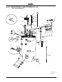
4
4
Feed Water
Dip Pipe
Removing/replacing Water Level Probe
Safety Valve
Outlet
Water Level
Gauge Blowdown
Water Column
Blowdown
Boiler Blowdown
Handhole
FIG. 20 BOILER MAINTENANCE
37
J Gas 08 2008
Feed Water Pump
Interrupt Switch
4
4
MAINTENANCE
SECTION 4
4.1
General
Maintenance on Gas appliances should only be carried out by competent, trained personnel who are CORGI/ACS registered, and who have the necessary equipment to check combustion.
If any fault is found during these operations contact your Fulton representative.
CAUTION
It is essential that regular checks are made to ensure that scale buildup is not
taking place within the boiler. Such checks will ensure that water treatment
being applied to the boiler feed water is effective.
The lower hand hole doors should be removed after one month of operation and the interior of the boiler thoroughly examined. If scale or sludge build up is observed, it should be removed and the water treatment supplier advised.
New gaskets must be fitted every time a handhole door is removed. Subsequent interior examinations should be carried out on a regular basis until satisfactory conditions are observed. Thereafter,
inspections should be carried out at three monthly intervals.
WARNING
Prior to the commencement of any work requiring the removal of cover
plates and the opening of control panel box, the electrical supply
to the boiler must be isolated.
The following procedures are designed to prevent the buildup of scale, silt or sludge in the bottom of the boiler, water gauge and water column pipework, some of the routines form part of the normal boiler operation as detailed in section 3.
In addition to these procedures, the advice of a water treatment specialist should be sought
and followed
4.2
DAILY.
Some of the following procedures should be carried out as part of the normal operating routines of the boiler, others are required to be done as part of the boiler maintenance programme.
All boiler operating routines and tests should be recorded and kept as a boiler history.
1. Blowdown the Boiler.
2. Blowdown the Water Column.
3. Blowdown the Water Level Gauge.
4.3 WEEKLY (including daily)
WARNING
Ensure the fittings around the steam safety valve(s) are secure.
The safety valve will be very hot, do not operate the safety valve without protection.
4. Ensure that the pipes from the safety valve outlet is not damaged and that it continues to a safe blowdown point.
5.
The water level and safety cut-off controls must be tested under operating conditions by
interrupting the water feed supply.
To carry out this test, use the feed pump interrupt switch to isolate the feedwater pump and lower the water level in the boiler by evaporation. Lower the water level passed both the 1st. and
2nd. low water levels (see section 3).
On completion of this test, switch off the pump interrupt switch and check that the water level
is restored to normal.
J Gas 08 2008
38
4
4.4
4
Monthly (including weekly)
6.
Inspect the hand holes in the boiler. If any leakage is evident proceed as follows:
Note: Use only genuine Fulton replacement parts.
a). Using the special tee handle wrench, remove the handhole assembly.
b).
Remove the old gasket and thoroughly clean the mating faces of the plate and boiler.
c).
Fit the handhole assembly as follows:
1.
Place the new gasket on the handhole plate and ensure that it is seating correctly.
Do not use any grease, lubricant or adhesive.
2.
Position the plate in the boiler, set the crab and tighten the securing nut only
sufficiently to provide a snug fit. Verify the position of the plate in the boiler to
ensure that there is uniform space between the periphery of the door and the
boiler inspection opening. Tighten the nut hand tight only. Using the special wrench, tighten the nut a further quarter of a turn. DO NOT OVERTIGHTEN.
d).
7.
Inspect the flanged joint covering the rear inspection port in which the blowdown valve is fitted,
if any leakage is evident replace the gasket.
8.
If the gasket leaks as the pressure is building up, tighten the securing nut only
sufficient to stop the leakage.
Clean the sight glass. If any leakage is evident, renew the gasket.
Note:Isolate the gas supply.
9.
Check and clean the ultra -violet cell (if fitted).
10.
Check feedwater and boiler water quality (see Water Treatrment in section 5).
Handhole Cover
Plate
Gasket
Crab
FIG. 21 REMOVING/REPLACING UV
DETECTOR
39
FIG. 22 HANDHOLE
J Gas 08 2008
4
4
4.5
THREE MONTHLY (including monthly)
11.
Drain and isolate the boiler.
12.
Remove the lower handhole assemblies and inspect the interior of the pressure vessel for
scale and sludge build up.
13.
Remove the feedwater pipe from the top of the boiler. Ensure the pipe is not blocked,
clean as required.
Caution
Ensure the gas supply is isolated.
14.
Disconnect the gas head from the burner by unscrewing the union.
Remove the burner plate screws, withdraw the burner assembly.
Clean the ignition electrodes and reset.
Insulating rope
Lower refractory
brick in place
FIG. 23 BOILER FURNACE
FIG. 25 BURNER PLATE
FIG. 24 IGNITION ELECTRODE
FIG. 26 BURNER ASSEMBLY
(suitable lifting equipment must be used to lift any heavy items)
J Gas 08 2008
40
4
4
4.6
SIX MONTHLY (including three monthly)
It should be noted that after a Fulton boiler has been in operation for several months, pieces of burned metal
will be found in the space at the bottom of the boiler. These pieces of metal are the remains of a light gauge
metal form which was used during manufacture for the forming of the boiler insulation. This is normal and does
not affect the efficiency or the life of the boiler in any way.
15.
Remove the cover plates and clean-out door. Clean out the flue passes, check the
refractories for soot or breakage, inspect the stainless steel ring. When replacing the cover
plates and clean-out door, use new gasket material and furnace cement to ensure a tight seal, thus preventing the escape of hot gases.
16.
Apply a small quantity of oil to the bearings of the burner motor and the feed water pump motor.
17.
Drain and flush the feed water tank. Clean any filters in the tank, in the feed water line or in
the feed water pump.
18.
Remove and clean the water level probes, take care not to crack the porcelain. After
replacement of the probes, check the operation of the low water cutoff relay and of
the feed water pump.
19.
20.
Remove the air gate and clean the fan.
Test the flue using the following procedure:
Visual Inspection
Check joints between all flue sections for quality of seals. Where the flue passes through the structure of the building use your judgement as to the integrity of this section of the flue.
Smoke Test
With the flue capped and a smoke generator inserted into the flue, their should be no smoke visible. If either of these tests fail, shut down the boiler and contact Fulton Boiler Works
immediately.
21.
Remove the water gauge and water column. Rod through the top connections of both to
ensure the holes in the baffle plates (approx.. 6mm dia.) inside the boiler are not obstructed.
22.
Check the burner combustion to ensure that excess air and carbon monoxide values are within normal limits (see combustion values in section 5).
23.
Check the condition of the gas valve filter (if fitted), renew as required.
Cleaning
the Flues
Remove cover
plates and gasket
Oil boiler illustrated.
FIG. 27 FLUE CLEANING
41
J Gas 08 2008
Remove the cleanout door to
the flue passes and to the
bottom of the boiler.
B
B
Appendix ‘B’
Motorised High/Low Control
1.1
Description
The Fulton motorised high/low control is designed to improve the efficiency of the boiler by
switching the firing rate from high fire (when there is low steam pressure in the boiler) to low fire (when the boiler reaches a high steam pressure).
The systems major components comprises; two stage gas valve, motorized air damper unit and two stage steam pressure switch.
CAUTION
The adjustment of the air gate control motor or the two stage
gas valve should only be carried out by qualified personnel,
incorrect adjustment could result in damage to the pressure
vessel and/or the production of harmful combustion gases.
Air Damper Housing
High / Low Fire Cams
Air Damper Motor
1.2
Operation
With the steam pressure switch preset to the high and low fire operational requirements of the system, and the boiler operating normally, steam pressure will gradually increase until the high pressure limit is reached, the pressure switch will then switch the two stage gas valve and the air damper motor to the low fire position.
The boiler will continue to operate at low fire until the steam pressure falls to the low pressure limit setting on the pressure switch, at this point, the gas valve and the air damper will switch the boiler into high fire mode, the sequence of high fire / low fire is regulated automatically with no routine maintenance required.
Note: Should the boiler attain the off setting of the on/off control pressure switch, the burner will switch off on low fire and then restart in the normal way on high fire.
1.3
Additional Controls
Low Fire Hold Switch - Used to maintain the boiler in the low fire mode during commissioning.
J Gas 08 2008
42
B
B
Motorised High/Low Control. continued.
2
Commissioning
(commissioning should only be carried out by a qualified Fulton Service Engineer).
To achieve the ideal combustion efficiency and gas input rates, a gas flow rate meter is required to measure the fuel input to the boiler.
2.1
Fuel Input Rates
Model
6
8
10
15
20
30
40
50
60
Low Fire
m3/h 3.5
4.7
5.8
8.7
11.6 11.6 23.2 29.0 34.8
ft3/min. 2.1
2.8
3.4
5.1
6.9
10.3 13.7 17.1 20.5
High Fire
m3/h 7.0
9.3
11.6 17.4 23.2 34.8 46.4 58.1 69.6
ft3/min. 4.1
5.5
6.8
10.2 13.7 20.5 27.3 34.2 41.0
Note: Boilers are pre-commissioned before leaving the factory to ensure optimum gas input rates and combustion values.
2.2
Air Damper Motor - Factory Cam Settings (see 2.3 Setup procedure)
Terminal
N1
N2
N5
N6
Position
High Fire Motor Cam
Low Fire Motor Cam
High Fire Interlock Cam
Low Fire Interlock Cam
Degrees
45O
10O
40O
15O
Blue cam N7 not used
Red cam N6
Red cam N5
Red cam N4 not used
Red cam N3 not used
Yellow cam N2
Yellow cam N1
Note: The high fire interlock cam should always be set approximately 5O lower than the high fire cam position. The low fire interlock cam should always be set approximately 5O higher than the low fire cam position.
43
J Gas 08 2008
B
B
Motorised High/Low Control. continued.
2.3
Setup Procedure
1.
Set the cams on the air damper motor to the initial position.
Start the boiler and wait until the motor and gas valve have driven to high fire.
Adjust the main (primary) air gate to achieve the best combustion with the least buffeting
in the furnace.
2.
Using the low fire hold switch, hold the boiler in low fire.
The air damper motor should move to its low fire position and the high fire light on the control panel extinguish, indicating the gas and air input rates have been reduced to approximately half the high fire input rate.
Note: If gas flow rate equipment is available, the low fire gas input rate should be adjusted to the correct
value (see fuel input rates table) by rotating the black 1st stage partial adjustment ring located below the 2nd
stage solenoid.
3. The ideal low fire CO2 constituent of the flue gases is 8 - 10.5%.
Place an exhaust gas analyser into the flue, reduce or increase the amount of air entering the boiler as required, by adjusting the low fire cam (N2) position.
Note: The reaction of the motor to a change in cam positions is:
Reduced air: adjust the cam to reduce the amount of air entering the boiler, the reaction of the motor will be immediate.
Increased air: adjust the cam to increase the amount of air entering the boiler, switch the low fire hold switch off. When the motor has driven back to high fire turn the low fire hold switch on, the damper will drive back to its new low fire position.
Adjust the cams until the correct CO2 figure is achieved.
Note: any adjustment to the cam positions requires an adjustment to its interlock cam position.
4. Switch off the low fire hold switch.
Note: if gas flow rate equipment is available, the high fire gas input rate can now be set (see fuel input rates
table) by adjusting the pressure control screw located under a protective cover on the black electrical connection block.
5.
Record all cam settings and the high and low fire final gas elbow pressures for future reference.
The high fire CO2 constituent of the flue gases is 10 - 10.5%.
Place an exhaust gas analyser into the flue, reduce or increase the amount of air entering the boiler as required, by adjusting the high fire cam (N1) position.
To reduce the amount of high fire air, the damper will have to be driven to its low fire position and back again, before it takes up its new position. Ensure that the high fire interlock cam N5 is always set approximately 5O below the high fire motor position cam N1.
6. Adjust the pressure switch (PS2) to the high/low switch over point.
J Gas 08 2008
44
B
B
Motorised High/Low Control. continued.
5.0
Spare Parts
Part No.
Description
Qty
Model
10366 13195 14437 14485 14486 14487 14489 5-10-000480
11327 14493 Casting, scroll Transformer, TRK2P COFI
Switch, air pressure, DL5A
Motor, damper, A30 045Y
Inlet, scroll
Fan, 200x40x16
Coupling, air gate
Airgate, high/low
Switch, low fire hold
Valve, gas, MB-ZRD(LE)410 B01
1
1
1
1
1
1
1
1
1
1
6 - 15
15
15
15
15
15
15
15
15
15
45
J Gas 08 2008
C
C
Appendix ‘C’
Spirax High Integrity Level Controls
The daily testing of boiler water level controls is a mandatory requirement as defined in the Health & Safety
Executive Guidance Note PM5.
The level of supervision is dependent upon the type of level controls (limiters) fitted.
Boilers fitted with self monitoring high integrity controls (limiters) should be tested daily by a qualified boiler attendant, but may be supervised during the silent hours and weekends by a Competent Person trained to respond to an alarm.
Daily testing of the controls is required which can be by simulation, with a weekly test by interrupting the feed
water pump and lowering the water by evaporation.
Daily Test
1st. Low Water
1. With the burner firing
2. Press and hold the 1st. Low Water test button until (minimum 15 seconds) the low water alarm sounds, and the low water indicator lamp illuminates, and the burner shuts down
3. Release the test button
4. After approximately 17 seconds the low water alarm will cancel, the low water lamp will
extinguish, and the burner will restart
2nd. Low Water
1. With the burner firing
2. Press and hold the 2nd. Low Water test button until (minimum 15 seconds) the low water alarm sounds, and the second low water reset switch illuminates, and the burner shuts down
3. Release the test button
4. After approximately 17 seconds the second low water relay will reset.
5. To cancel the second low water level alarm and light, depress the second low water reset switch
6. The burner will restart.
HIGH INTEGRITY LEVEL LIMITERS
TEST
TEST
1st. LOW WATER
2nd. LOW WATER
TEST:
with the boiler water at the normal working level,
press and hold each control for a minimum of
15 seconds, until the alarm sounds.
J Gas 08 2008
46
C
C
Spirax High Integrity Level Controls, continued.
Weekly Test (Daily test plus)
1st. Low Water
1. With the burner firing
2. Switch the pump interrupt switch to the pump interrupt position.
3. By evaporation lower the water level in the boiler until the first low water alarm sounds and the low water indicator lamp illuminates, and the burner shuts down
4. Switch the pump interrupt switch to the pump on position.
5. The pump will start and restore the water level to the normal position and switch off.
6. After approximately 17 seconds from restoring the first low water level the low water alarm will cancel, the low water lamp will extinguish, and the burner will restart
2nd. Low Water
1. With the burner firing
2. Switch the pump interrupt switch to the pump interrupt position
3. By evaporation lower the water level in the boiler until the low water alarm sounds, the second low water reset switch illuminates, and the burner shuts down.
4. Switch the pump interrupt switch to the pump on position.
5. The pump will start and restore the water level to the normal position and switch off.
6. After approximately 17 seconds from restoring the second low water level the second low water relay can be reset.
7. To cancel the second low water level alarm and light, depress the second low water reset switch
8. The burner will restart.
Note: These tests can be carried out consecutively, however it is possible that if the boiler is under load
conditions the second low water alarm will occur immediately after the burner has shut down on first low
water, without the apparent loss of any more water. The reason is the collapse of the steam bubbles at the
water level surface when the heat is removed. The degree of collapse could be such that the water level will
disappear from the bottom of the site glass before the alarm sounds. Should this happen the second low
water level alarm should be checked by lowering the water level slowly by partially opening the main blowdown valve.
Pump Interrupt Switch
47
J Gas 08 2008
D
D
Appendix ‘D’
Automatic TDS Blowdown System
The purpose of an Automatic, Total Dissolved Solids (TDS) Control Blowdown System, is to control the TDS
level within the boiler around a set point. It is not a substitute for the main boiler blowdown, which must be
used to control suspended solids, and prevent the build up of sludge in the bottom of the boiler.
The method of operation is to take a sample of the boiler water at preset timed intervals, pass the sample over
an electrode which measures water conductivity (which is proportional to TDS for a given water chemistry),
and then compares the result with the control value (normally 2000ppm), which is set when the unit is commissioned.
If the sample value is higher than the control value the blowdown solenoid valve opens in a series of pulses until
the measured value corresponds to, or is lower than, the set value. When this is achieved blowdown finishes
until the next timed sample is taken when the process is repeated. Should the sample value be lower than the
set value, blowdown is deferred until the next timed sample.
For the system to function reliably, the control must be calibrated to a typical water sample that is representative
of the water conditions that are likely to prevail during normal running of the boiler and system.
Conductivity and as a consequence TDS, can vary significantly with water chemistry. Changes in condensate
return rates, alkalinity, chemical dosage, and suspended solids can all affect the performance of an Automatic
TDS Blowdown System.
Condensate return rates that vary greatly on a day to day basis can severely disrupt the reliability of the conductivity measurement.
FIG. 1
e.g. A boiler with a 50% condensate return and a raw water TDS of 400
will have a boiler feed water TDS of 200 ppm.
J Gas 08 2008
48
D
D
Automatic TDS Blowdown Systems, continued.
Systems that return for example very little condensate during the day, but a high proportion at night are almost
impossible to control with any real accuracy. At best a compromise calibration will be achieved, where too much
blowdown at times may be the penalty.
When installing and commissioning a new Automatic TDS Control Blowdown System, it must be accepted that
the calibration will be a reiterative process, requiring continual sampling, testing, and re-calibration until stable
system operating conditions are achieved.
When purchasing an Automatic TDS Control Blowdown System from Fulton Boiler Works (Great Britain)
Ltd, the equipment would normally be supplied with the controller wired and fitted to the boiler control
panel, with all the other parts supplied loose for piping and wiring on site by others, unless agreed
otherwise in our order acknowledgement.
The purchase price of the system supplied fully or part fitted includes for one single visit to commission the
system once installed. Part of the commissioning process will be the initial calibration of the TDS sensor to the
water conditions prevailing at the time.
Further re-calibration will be required until the water treatment regime has been established, and “typical” water
conditions have been achieved. Routine calibration checks will be required as part of the site maintenance and
water treatment monitoring.
The equipment, staff training required to carry out TDS sampling, and calibration can be provided by Fulton
Boiler Works (Great Britain) Ltd. if required. In order to achieve the maximum benefit from the installation of an
Automatic TDS Blowdown System, it is strongly recommended that site personnel be provided with the necessary equipment, and training in order for them to fully understand the function of the system, and the possible
consequences of their actions.
Note:- Where Automatic TDS Blowdown systems are provided as part of a skid mounted or packaged plant
room unit, they will be fully installed piped and wired.
e.g. Hourly blowdown rate required to maintain a boiler TDS of 2000
with a feed water TDS of 200 = 12%
For a 1000kg/h boiler 125kg/h (125l/h) of blowdown is required.
49
J Gas 08 2008
5
5
GENERAL DATA
SECTION 5
Steam
Outlet
H
Feed Water Inlet
Flue Connection
Gas Inlet
L (dia)
J
H
A
B
C
E
D
F
360O
P
M
G1
Boiler
Blowdown
Q
N
K
FIG. 28 BOILER DIMENSIONS
Model 6J
8J
10J
15J
20J
30J
40J
50J
60J
A**
B
C
D
E
F
G1
H
J
K
L
M
N
P
Q
2300
1840
1060
1025
1670
1845
2045
1500
1810
380
152
715
1025
265
270
2300
1840
1060
1025
1670
1845
2045
1500
1810
380
152
715
1025
265
270
2460
1990
1215
1175
1820
2010
2225
1625
1960
380
203
760
1060
265
270
2600
2060
1285
1245
1890
2100
2330
1670
2030
390
255
985
1400
265
270
2800
2240
1465
1385
2070
2310
2510
1820
2210
390
305
1175
1595
265
270
3100
2490
1710
1670
2320
2680
2820
2075
2460
395
305
1390
1850
265
265
3100
2490
1710
1670
2320
2680
2820
2075
2460
395
305
1390
1850
265
265
3100
2490
1710
1670
2320
2680
2820
2075
2460
395
305
1390
1850
265
265
2300
1840
1060
1025
1670
1845
2045
1500
1810
380
152
715
1025
265
270
Dimensions (mm)
Standard Boiler Trim.
Main Steam Valve
Steam Safety Valve
Steam Pressure Gauge Assembly
Boiler Blowdown Valve
Water Level Gauge Set
Feedwater Check Valve
Feedwater Stop Valve
Flue Spigot
Audible Alarm
Flue Brush
Tee Handle Wrench
Quantity
1
1
1
1
1 or 2*
1
1
1
1 or 2*
1
1
J Gas 08 2008
GAS COMBUSTION VALUES
CO2 range
CO O2 Excess air
Smoke
9.5 - 10.5%
less than 50ppm
4.3 - 2.5%
25 - 15%
-
50
5
5
Specification
6J
8J
10J 15J 20J 30J 40J 50J 60J
Output kg/h (F & A 100oC) 96 128 160 240 320 480 640 800 960
Std. working pressure. (bar). 10.3410.3410.3410.3410.3410.3410.3410.3410.34
Boilers at higher pressures are available as special orders
Firing Rates
Gas (m3/h) 7.09.311.6 17.4 23.2 34.8 46.4 58.1 69.6
The mains gas supply pressure must be between 18.5mb and 50mb.
Electrical Requirements
FLC (400V, 3ph, 50Hz) amps FLC (230V, 1ph, 50Hz) amps Water Content (litres)
4.74.74.74.74.94.96.96.98.6
12.7 12.7 12.7 12.7 14.9 - 91
91
- - -
91
205 291 640 1022 1022 1022
Weight dry (approx. kg) 810 810 810 1190 1420 2030 3150 3150 3150
Weight full (approx. kg) 900 900 900 1395 1711 2670 4172 4172 4172
Connection Sizes (DN) (F=female, M=male) (all connections BSP)
Steam Outlet 20F 20F 25F 32F 32F 40F
Feed Water 15M 15M 15M 15M 15M 15M
Safety Valve (discharge) 20F 20F 20F 20F 20F 20F
Blowdown (Boiler) 20F 20F 20F 20F 25F 25F
Blowdown (Water column) 20F 20F 20F 20F 20F 20F
Blowdown (Sight Glass) 8F 8F 8F 8F 8F 8F
Gas Inlet 20F 20F 20F 32F 32F 32F
50F
15M
32F
25F
20F
8F
50F
50F
15M
32F
25F
20F
8F
50F
50F
15M
32F
25F
20F
8F
50F
Ventilation - High and Low levels
51
Boiler Model
6J
High Level (cm2)
Low Level (cm2)
8J
10J
15J
20J
30J
40J
50J
60J
305 360
420
560
700
980
1260
1540
1820
610 720
835
1115
1395
1960
2520
3085
3645
J Gas 08 2008
issue1
5
5
IMPORTANT
Recommended Water Conditions
It is very important that a strict water management program is followed
to ensure trouble free boiler operation.
The following are recommended for feedwater and for boiler water.
FEEDWATER (water entering boiler)
pH Value
Hardness
Suspended Solids
Chloride
Organic Matter
Oil
8.5 to 9.5 tested at room temperature.
less than 2.0mg/kg in the form of CaCO3
None
Less than 50mg/kg
Less than 5mg/kg
None
BOILER WATER (water inside boiler)
pH Value
Hardness
Suspended Solids
Chloride
Oxygen Scavenger,
Sodium Sulphide or Tannin
Phosphate
Total Alkalinity
Caustic Alkalinity
9.5 - 11.5, tested at room temperature
Not detectable
Less than 100 mg/kg
Less than 500 mg/kg
Total Dissolved Solids (TDS)
Iron
Silica
Dissolved Oxygen
Less than 2000ppm
Less than 1 mg/kg
Less than 180 mg/kg, in the form of SiO2
None
20 to 50 mg/kg
Less than 50mg/kg, in the form of PO4
Less than 1000 mg/kg
Less than 300 mg/kg as CaCO3
mg/kg =
CaCO3 =
PO4 =
SiO2 =
1 Grain hardness =
therefore 70 ppm =
For practical purposes mg/kg = Milligrams per Kilogram
Calcium Carbonate
Phosphate
Silicon Dioxide
17.118 ppm
4.10 grains hardness.
ppm
It is critical that the boiler water pH be alkaline in the range 9.5 -11.5.
Daily boiler blowdown is essential to help prevent formation of deposits
and reduce Total Dissolved Solids (TDS).
Consult your Water Treatment specialist to establish the frequency and duration
of blowdown required to achive the required conditions.
J Gas 08 2008
52
5
5
PROBE LENGTHS (TI65)
Centre
of
Glass
Pump On
241
Pump Off
216
High Water Probe
216
Top of Sockets /
Shell / Furnace
2nd Low Water
430
1st Low Water
405
DATUM:
underside of
probe hex.head
1st Low Water
2nd Low Water
Note: 350 Sight Glass
Probe Lengths
High Level
216
1st Low Water 405
2nd Low Water 430
Probe Lengths
Pump Off
Pump On
measurements in mm
’J SERIES’ BOILER PROBE LENGTHS
53
J Gas 08 2008
216
241
PE
N
L1
L2
L3
J Gas 08 2008
~
M
3
6.
M
~
4.
5.
MOTOR CONTACTOR
FEED PUMP
FEED PUMP MOTOR
CT1
PE
NOTE:
FOR CIRCUIT CONTINUATION INSTRUCTION REFER TO DRAWING EJ060000.
FEED PUMP MOTOR
BURNER MOTOR CONTACTOR
BURNER MOTOR CT1
BURNER MOTOR
3
1.
2.
3.
INTERLOCKED DOOR ISOLATOR
~
(IF FITTED)
OIL PUMP MOTOR
M
7.
8.
9.
3
2A MCB
SUPPLY CIRCUIT
(FOR GAS, OIL & DUAL FUEL BOILERS)
6J-60J SERIES PANEL
OIL PUMP MOTOR
CONTACTOR (IF FITTED)
OIL PUMP MOTOR CT1 (IF FITTED)
2A MCB
2A MCB
1:1 TRANSFORMER
CN
N
L1
L2
L3
C
EJ06 0001-1
SINGLE PHASE SUPPLY
5
5
FIG. 29 THREE PHASE SUPPLY CIRCUIT
54
J Gas 08 2008
M
2
MCB
FEED PUMP MOTOR
CONTACTOR
FEED PUMP
MOTOR CTI
FIG. 30 THREE PHASE SUPPLY CIRCUIT - AUSTRALIAN BOILERS ONLY
3-PHASE SUPPLY CIRCUIT
(FOR BOILERS WITHOUT TRANSFORMER)
FOR ISSUE EDITS, REFER TO NUMBER IN CIRCLE: #
FOR CIRCUIT CONTINUATION INSTRUCTION REFER TO DRAWING
EJ060000.
6J-60J SERIES PANEL
FEED PUMP
MOTOR
3
~
M
BURNER
MOTOR
3
~
BURNER MOTOR
CONTACTOR
2
BURNER MOTOR CTI
NOTE:
FOR SINGLE PHASE PANELS ONLY 'L1' WILL BE WIRED.
PE
N
L1
L2
L3
1
2
3
55
4
5
6
INTERLOCKED DOOR
ISOLATOR
EJ06 0011-2
CN
C
5
5
J Gas 08 2008
FIG. 31 ANCILLARY CONTROL CIRCUIT
56
CN
13
14
2
FUSED TERMINAL
18
19
WATER SOFTENER
16
17
CHEMICAL
DOSING
22
23
BURNER ON
R7
(IF FITTED)
BC AUX
PC AUX
PC
BCT1 AUX
PUMP CT1
AUX
PUMP INTERRUPT
PL1 (3)
R11 (IF FITTED)
24
26
R5
27
5
R6
OIL/GAS
SELECTOR
SWITCH
(IF FITTED)
R11A (IF FITTED)
5
28
29
4
{
2
REMOTE
STOP
C
TC (IF FITTED)
TC
(IF FITTED)
15
BURNER RUN
20
21
CONDENSATE TANK
TANK LOW WATER PUMP
INTERRUPT
PM5 CONNECTIONS
{
25
25
REMOTE PANEL
BOILER TESTING
SW/1
30
R2
34
35
R1
31
32
33
36
3
ANCILLARY CONTROL CIRCUIT
(FOR GAS, OIL & DUAL FUEL BOILERS)
6J-60J SERIES PANEL
NO VOLT CONTACTS
1st LOW
WATER
2nd LOW
WATER
FLAME
FAILURE
{
{
{
{
HIGH PRESSURE
(IF FITTED)
OIL
FIRING
OIL/GAS
SELECTOR
SWITCH
GAS
FIRING
R3
37
38
39
R4
40
41
R7
44
45
SEQUENCE
CONTROL
(IF FITTED)
42
43
REMOTE STOP
(IF FITTED)
POWER ON
R8
OPC AUX
(IF FITTED)
OIL PUMP RUN
(IF FITTED)
OIL PUMP CT1 AUX
(IF FITTED)
EJ06 0002-5
BC
A
CN
R11 (IF FITTED)
C
TDS
(17)
OPC (IF FITTED)
5
5
CN
5
20
1
6/30 ONLY
59
14 15 16 17 18
FLAME
MAIN GAS
SENSOR
61
GAS VALVE
60
(6-30 ONLY)
8
63
P
11
9
R5
(IF FITTED)
7
3
SATRONIC TMG 740-3
2
R3
REFER TO DRAWING EJ060000.
AIR SWITCH
R2
(40-60 ONLY)
VALVE
PILOT GAS
(FOR GAS BOILERS ONLY)
BURNER CONTROL CIRCUIT
6
(IF FITTED)
AUTO MANUAL SWITCH
6J-60J SERIES PANEL
2
2nd SPIRAX
(6+7)
IGNITION
IGNITION
2. FOR CIRCUIT CONTINUATION INSTRUCTION
40/60 ONLY
NORMALLY 'CLOSED' SIDE OF THE SWITCH.
62
IF LC LEVEL CONTROLS FITTED,
USE: LW1 (5, 6)
or
1st SPIRAX LEVEL CONTROLS FITTED,
USE: (6+7)
HIGH FLAME
TERMINAL 10 WILL BE FED FROM THE
R8
(40-60 ONLY)
MAIN GAS VALVE
69
OF THE PRESSURE SWITCH, AND SATRONIC
PS2
BE FED FROM THE NORMALLY 'OPEN' SIDE
21
PS1
10
(IF FITTED)
PS4 SET BACK PRESS
40/60 ONLY
1. IF USING PROPANE GAS, THE LIGHT WILL
LOW FLAME
NOTES:
P
72
19
58
FLAME FAILURE RESET
64
A
65
START GAS
66
MAIN GAS
67
40/60 ONLY
68
40/60 ONLY
71
FIG. 32 BURNER CONTROL CIRCUIT
70
R4
73
J Gas 08 2008
74
HIGH PRESSURE
(IF FITTED)
PS3
GAS PRESSURE
SWITCH
(SEE NOTE 1)
CC
EJ06 0006-3
CN
(IF FITTED)
RESET
HIGH PRESSURE
R4 (IF FITTED)
57
R4 (IF FITTED)
CC
5
5
CN
A
1
2
G
23
FLAME
SENSOR
13
4 12 14
FLAME FAILURE RESET
P
AIR SWITCH
CPI SWITCH
21
3
START GAS
IGNITION
65
66
FLAME FAILURE
PILOT
HOLD
PILOT
GAS VALVE
18
6
6J-60J SERIES PANEL
BURNER CONTROL CIRCUIT
(FOR AUSTRALIAN BOILERS ONLY)
16
IGNITION
R3
LANDIS LFL-1-335
67
68
19
8
2. FOR CIRCUIT CONTINUATION INSTRUCTION
REFER TO DRAWING EJ060000.
MAINS GAS
7
62
63
64
1. IF USING PROPANE GAS, THE LIGHT WILL
BE FED FROM THE NORMALLY 'OPEN' SIDE
OF THE PRESSURE SWITCH, AND LANDIS
TERMINAL 4 WILL BE FED FROM THE
NORMALLY 'CLOSED' SIDE OF THE SWITCH.
PS2
MAIN
GAS VALVE
HIGH FLAME
40/60 ONLY
5
LW1
4
R2
P
PS1
HIGH PRESSURE
RESET
(IF FITTED)
PS3
(IF FITTED)
GAS
PRESSURE
SWITCH
(SEE
NOTE 1)
HIGH PRESSURE
NOTES:
LOW FLAME
40/60 ONLY
72
CPI
60
E
R4
73
J Gas 08 2008
74
R4 (IF FITTED)
CN
CC
EJ06 0012-1
R4 (IF FITTED)
CC
5
5
FIG. 33 BURNER CONTROL CIRCUIT - AUSTRALIAN
58
FIG. 34 HIGH - LOW, BURNER CONTROL CIRCUIT
13
8
1
19
3
FLAME
SENSOR
2
2
15
R10
R9
P
2 1 6 22 7 5 N
AIR DAMPER MOTOR
5
R12
R10
16 17 18
20
3
11
14
R9
7
9
R9
12
LOW
FIRE
HOLD
R9
10
R4
P
MANUAL
R8
GAS 2
PRESSURE
(IF (FITTED)
R4
(IF FITTED)
5
AUTO/MANUAL
SWITCH
(IF FITTED)
PS3
(IF FITTED)
GAS PRESSURE
SWITCH
(SEE NOTE 1)
5
R2
AUTO
BURNER CONTROL CIRCUIT
(FOR HIGH/LOW GAS BOILERS ONLY)
FOR ISSUE EDITS, REFER TO NUMBER IN CIRCLE:
21
PS1
2nd SPIRAX (6+7)
LW1 (5+6) LC
or
1st SPIRAX (6+7)
6J-60J SERIES PANEL
MAIN
GAS VALVE
6
START
GAS
2
4
IGNITION
R3
3
SATRONIC TMG 740-3
NOTES:
1. IF USING PROPANE GAS, THE LIGHT WILL BE FED FROM THE
NORMALLY 'OPEN' SIDE OF THE PRESSURE SWITCH, AND
SATRONIC TERMINAL 10 WILL BE FED FROM THE NORMALLY
'CLOSED' SIDE OF THE SWITCH.
2.FOR CIRCUIT CONTINUATION INSTRUCTION REFER TO
DRAWING EJ060000.
CN
5
R12
'A'
60
61
R5
(IF
FITTED)
107
BC AUX
62
63
64
PS4 SET BACK
PRESSURE
( IF FITTED )
C
IGNITION
65
66
PS2
LOW
FLAME
HIGH FLAME
FLAME FAILURE
RESET
100
101
102
103
104
105
106
AIR
SWITCH
START GAS
67
68
MAIN GAS
69
70
71
J Gas 08 2008
72
73
74
#
CN
2
EJ060010-6
R10
2
CC
HIGH STEAM PRESSURE RESET
(IF FITTED)
R4 (IF FITTED)
59
HIGH STEAM PRESSURE (IF (FITTED)
CC
5
5
FLAME
FAILURE
33
34
35
2nd LOW
WATER
24V SUPPLY
FROM PM5
25
25
24
26
BOILER 'A'
36
37
38
NOTE:
USE SAME TERMINAL CONNECTIONS FOR BOILER 'B' & 'C' AS
FOR 'A', & CONNECT TO THEIR RELEVANT PM5 REMOTE PANEL
TERMINALS.
FUSED ISOLATOR
2A MCB
240./24.V
28
29
BOILER
TESTING
'A'
27
2A MCB
'B' 'C'
'A'
'A'
EMERGENCY STOPS
'B'
'B'
'C'
'C'
24V SUPPLY
FROM PM5
BOILER 'B' (SEE NOTE)
FLAME
FAILURE
2
N
I3 I6
Q3
'C'
BOILER
TESTING
'C'
I2 I5
LOGO
Q2
'B'
'B'
Q1
'A'
BOILER ALARM
'A'
I1 I4
L
PM5 REMOTE PANEL & TYPICAL BOILER CONNECTIONS
(FOR GAS, OIL & DUAL FUEL BOILERS).
2nd LOW
WATER
35
2A MCB
28
29
2nd LOW
WATER
I7
24V SUPPLY
FROM PM5
BOILER 'C' (SEE NOTE)
FLAME
FAILURE
Q4
MUTE
'B' 'C'
EAC06 0001-2
BOILER
TESTING
'A'
11
11
11
FUSE
33
34
1
1
1
36
37
38
5
6
36
37
38
3
25
25
24
26
7
8
25
25
24
26
4
27
9
10
33
34
35
J Gas 08 2008
28
29
MAINS SUPPLY
5
5
FIG. 35 PM5 REMOTE PANEL / TYPICAL BOILER CONNECTIONS
60
27
5
61
5
FIG. 36 TANK SOLID STATE WATER LEVEL AND ALARM CIRCUITS
J Gas 08 2008
J Gas 08 2008
CHEMICAL
DOSAGE
FEED
TANK
PUMP
WATER
SOFTENER
PUMP
INTERRUPT
RELAY
REMOTE
STOP
LINK
N
L
N
L
N
L
L3
L2
L1
14
14
16
13
13
16
12
12
15
11
11
15
10
9
8
7
6
5
4
3
2
1
E
10
9
8
7
6
5
4
3
2
1
E
PUMP
ELECTRICAL CONNECTIONS
(FOR GAS, OIL & DUAL FUEL BOILERS)
& ANCILLARY SKID
STANDARD SINGLE BOILER
14
13
-
-
-
23
22
21
20
19
18
17
16
6
5
4
E
BOILER TERMINALS
SCREENED CABLE
GREEN
BLUE
YELLOW
RED
BOILER SKID
BLUE
RED
TDS PROBE
EAC06 0003-1
NOTE:
PUMP MAYBE FITTED ON THE BOILER SKID OR ANCILLARY SKID.
4
3
2
1
79
78
87
86
85
84
83
82
BOILER TERMINALS
(REF.)
PLUG & SOCKET
TDS & BOTTOM BLOWDOWN CONNECTION (REF.)
TDS PROBE CONNECTION
VALVE
OPEN
ALARM
TDS
SOLENOID
VALVE
CLOSED
SWITCH
BOTTOM BLOWDOWN
SOLENOID VALVE
AUXILLARY SKID
5
5
FIG. 37 STANDARD SINGLE BOILER AND ANCILLARY SKID ELECTRICAL CONNECTIONS
62
FIG. 38 SPIRAX LEVEL CONTROL CIRCUIT
J Gas 08 2008
HIGH
WATER
(IF FITTED)
HIGH WATER ALARM
(IF FITTED)
NOTE:
FOR CIRCUIT CONTINUATION INSTRUCTION
REFER TO DRAWINGS:
EJ060000 (FOR 'J' SERIES BOILERS);
ERB060000 (FOR RBC BOILERS).
CN
4
3 HL1
(IF FITTED)
5
8
1
6
2
1
PL1
5
2
52
R6
1
2
LP30
1st LOW
WATER
9101112
LC3000
1st
1
5
3
1
2nd LOW WATER
RESET BUTTON
R2
2
9 101112
LP30
2nd LOW
WATER
4
3
LC3000
2nd
1
R2
2nd LOW WATER LIGHT & ALARM
CN
CC
EGP06 0001-2
1 DENOTES LOCATION OF CHANGES FOR ISSUE NUMBER
1st LOW WATER LIGHT & ALARM
1st LOW WATER TEST
BUTTON
SPIRAX LEVEL CONTROL PANEL CIRCUIT
(FOR GAS, OIL & DUAL FUEL BOILERS)
PUMP PUMP
OFF
ON
6
8
3
7
4
51
7
50
OFF
R1
PUMP &
BOILER
R2
PUMP
ONLY
2nd LOW WATER TEST
BUTTON
63
PL1 (3)
C
SWITCH
SELECTOR
5
5
CN
PL1 (3)
2
HL1
4
(IF FITTED)
5
1
8
HIGH WATER
(IF FITTED)
3
7
6
8
3
4
5
1
1st LOW WATER ALARM
R1
R6
R2
LC LEVEL CONTROL PANEL CIRCUIT
(FOR GAS, OIL & DUAL FUEL BOILERS)
PUMP
ON
1
PL1
2
PUMP
OFF
7
51
6
52
J Gas 08 2008
50
OFF
7
1
LW1
2
1st LOW
WATER
8
3
4
53
PUMP &
BOILER
7
1
LW2
2
5
LOW WATER
RESET BUTTON
2nd LOW
WATER
6
8
3
4
54
R2
EGP06 0002-1
R2
SWITCH SELECTOR
PUMP
ONLY
CC
CN
2nd LOW WATER
RESET
C
5
5
FIG. 39 LC LEVEL CONTROL CIRCUIT
64
2nd LOW WATER ALARM
HIGH WATER ALARM
(IF FITTED)
FIG. 40 TDS AND BLOWDOWN CONTROL CIRCUITS
CN
FUSED TERMINAL
RED BLUE
TDS PROBE
SCREENED CABLE
RED
YELLOW
BLUE
GREEN
20
19
18
17
16
15
PC 'A' AUX
PC 'B' AUX
(If fitted)
TDS
CONTROL
(IF FITTED)
1
2
3
4
TDS
CONTROLLER
SUPPLY
80
81
BLOWDOWN
CONTROL
BT1000
(IF FITTED)
TDS & BLOWDOWN CONTROL PANEL CIRCUIT
(FOR GAS, OIL & DUAL FUEL BOILERS)
TDS
SOLENOID
VALVE
78
79
1
2
3
4
6
8
10
12
82
83
CLOSED
SWITCH
SOLENOID
VALVE
OPEN
ALARM
PC 'A' AUX
PC 'B' AUX
(If fitted)
84
85
J Gas 08 2008
86
87
65
TDS (17)
CC
EGP060003-1
CN
CC
5
5
88
89
5
5
J Gas 08 2008
66
Softened water
Brine level correct
Signature of operator
Water treatment
pH
TDS
Boiler water test
Pressure gauge reading
Time test carried out
Main boiler blowdown
duration/seconds
Feed pump, start/stop
Test by lowering water level
1st. low water alarm
Burner cut out
and alarm sounded 2nd. low water alarm
Burner lock out
and alarm sounded
Water Level Control
Water Level (by sight)
1st. gauge
2nd. gauge
Date
Water gauge blowdown
test satisfactory
STANDARD BOILER CONTROLS TESTS - LOG
Yes/No
Yes/No
Yes/No
Yes/No
Yes/No
Yes/No
Yes/No
Yes/No
Yes/No
Yes/No
Yes/No
Yes/No
DAILY TEST
Yes/No
Yes/No
Yes/No
Yes/No
Yes/No
Yes/No
Yes/No
Yes/No
Yes/No
Yes/No
Yes/No
Yes/No
Yes/No
Yes/No
Yes/No
Yes/No
Yes/No
Yes/No
Yes/No
Yes/No
Yes/No
Yes/No
Yes/No
Yes/No
Yes/No
Yes/No
Yes/No
Yes/No
Yes/No
Yes/No
Boiler No.
Flame failure
device tested
WEEKLY TEST
The following tests are to be performed in accordance with the maintenance schedule in the Fulton Service Manual.
J Gas 08 2008
Date
6
6
SPARE PARTS
SECTION 6
Using the appropriate information as completed below,
order spare parts from the Fulton Spare Parts Manual
provided with the boiler
In order to ensure spare parts are correct, please complete the
details below and have them at hand when ordering parts or
making enquires regarding the boiler.
1.
Boiler number
2.
Boiler type
3.
Type of fuel used
5.
Wiring Diagram No.
6. Commissioning Date
WARNING
The type, size and lift pressure of the safety valve fitted to a boiler is specific to that boiler.
When ordering new safety valves it is important that, as well as the information requested
above, the following additional information is given:
Boiler design pressure (located on the boiler data plate).
Make and type (eg fig no.) of safety valve fitted.
J Gas 08 2008
68
A0-1-1 GAS BOILER - MAJOR COMPONENTS
3
2
4
7
6
5
1
J Gas 08 2008
A0-1-1 GAS BOILER - MAJOR COMPONENTS
Item
1
Part Number Qty
2
4
5
6
7
not illustrated
1
1
1
1
1
1
1
1
1
1
1
1
1
1
1
1
1
1
1
A/R
1
1
1
1
1
1
Description
Boiler Shell & fittings
Boiler Shell & fittings
Burner assembly
Burner assembly
Burner assembly
Burner assembly
Gas train assy, monobloc
Gas train assy, monobloc
Gas train assy, monobloc
Gas train assy, monobloc
Gas train assy, monobloc
Gas train assy, m,bloc, Aus.
Burner scroll assembly
Burner scroll assembly
Burner scroll assembly
Burner scroll assembly
Burner scroll assy, dual fuel.
Water column
Water column
Water level gauge
Control box
Control box
Control box
Control box
Control box
Feed water pump
J Gas 08 2008
Remarks
see A1-1-1
see A1-2-1
see B1-1-1
see B1-2-1
see B1-3-1
see B1-4-1, Aus.
see C1-8-1
see C1-9-1
see C1-11-1
see C1-12-1, Aus.
see C1-13-1, LPG
see C1-14-1, LPG
see D1-1-1
see D1-1-2
see D1-2-1
see D1-3-1
see D2-5-1
see E1-3-1, Aus.
see E1-6-1
see F1-4-1
see G1-1-1
see G1-3-1
see G1-5-1, Aus.
see G1-6-1, Aus.
see G1-7-1, Aus.
see H1-1-1
Size
4 - 15
20 - 60
6 - 15
20 - 30
40 - 60
40 - 60
6 - 15
20 - 30
40 - 60
40 - 60
6 - 60
40 - 60
6 - 10
15
20 - 30
40 - 60
40 - 60
6 - 60
6 - 60
6 - 60
6 - 15
40 - 60
6 - 15
20 - 30
40 - 60
6 - 60
A1-1-1 BOILER SHELL AND FITTINGS, 6 - 15
(UK and Australia)
2
13
3
4
21
6
5
4
20
15
22
7
28
27
23
17 19
18
17
19
16
26
8
1
25
14
9
24
11
12
10
A1-1-1, 6-15
J Gas 08 2008
A1-1-1 BOILER SHELL AND FITTINGS, 6 - 15
(UK and Australia)
Item
Part Number Qty
1
10535
10536
10537
10566
SA0001
10565
10548
10655
10564
1
1
1
1
1
2
1
1
1
Valve, steam stop
Valve, steam stop
Valve, steam stop
Gauge, pressure
Gauge, pressure assy.
Tee
Valve
Plug
Syphon, pigtail
DN20
DN25
DN32
4in. x 250psi
6-8
10
15
6 - 15
6 - 15
6 - 15
6 - 15
6 - 15
6 - 15
8
9
10001
12037
12040
1
1
1
Refractory, furnace
Refractory, furnace
Refractory, furnace
Top
Top
Bottom
6 - 10
15
6 - 15
10
11
12
13
14
15
16
17
18
19
20
21
22
23
24
25
26
27
28
10006
13764
10009
10010
10011
10017
10023
11524
14257
SA0002
11824
14126
11825
10417
11882
11774
099E9360
10558
11504
11609
11952
11953
14187
14433
10135
10022
13508
13510
13509
13511
13568
SA0045
SA0040
010E 9520
015E9520
1
A/R
A/R
A/R
A/R
A/R
1
1
1
1
2
1
2
1
1
1
2
2
1
2
1
1
1
1
A/R
1
1
1
1
1
3
1
1
2
2
Door, cleanout
Handhole assembly
Bottom
Handhole assembly
Top
Handhole assembly
Top
Handhole assembly
Top
Gasket, handhole
Wrench, tee
Handhole
Valve, blowdown
Valve, feed water stop
Valve, check assembly
Gasket
Valve, check
Flange
Probe, water level
Probe, water level
Probe, water level
Basket, probe
Valve, steam safety 3/4in.Bir.130psi
Valve, steam safety
3/4in.N.V.130psi
Valve, steam safety
3/4in.Bir.125psi
Valve, steam safety Superseded
Valve, steam safety
Superseded
Valve, steam safety
1/2in. 165psi
Valve, steam safety
1/2in. 125psi
Gasket, flue cover
Brush, flue
Connector, flue, male
6in.
Connector, flue, male
8in.
Connector, flue, female
6in.
Connector, flue, female
8in.
Clip, flue connector
Pipe, feed water dip
Pipe, feed water dip
for TDS systems
Cover, shell flue
Cover, shell flue
2
3
4
5
6
7
Description
Remarks
Size
6 - 15
6 - 15
6-8
10
15
6 - 15
6 - 15
6 - 15
6 - 15
6 - 15
6 - 15
6 - 15
6 - 15
6 - 15
6-8
10 - 15
6 - 15
6 - 15
6 - 15
6 - 15
6 - 15
6 - 15
6 - 15
6 - 15
6 - 15
6 - 15
6 - 10
15
6 - 10
15
6 - 15
6 - 15
6 - 15
6 - 10
15
Note: In order to comply fully with safety regulations it is essential that the correct safety valves are used. If in
any doubt please contact Fulton Service Department for assistance.
J Gas 08 2008
A1-2-1 BOILER SHELL AND FITTINGS, 20 - 60
(UK and Australia)
21
17
26
22
19
23
24
22
20
6
18
25
15
7
16
4
3
5
4
3
2
14
27
1
13
12
28
8
10
11
9
A1-2-1 20/60
June 07
J Gas 08 2008
A1-2-1 BOILER SHELL AND FITTINGS, 20 - 60
(UK and Australia)
Item
Part Number Qty
Description
Remarks
1
10537
1
Valve, steam stop
DN32
10538
1
Valve, steam stop
DN40
10539
1
Valve, steam stop
DN50
2
SA0044
1
Valve, check assembly
3
11825
2
Flange
4
11824
2
Gasket
5
14126
1
Valve, check
6
14257
1
Valve, feed water stop
DN15
7
SA0045
1
Pipe, feed water
8
13732
1
Brush, flue
9
10006
1
Door, cleanout
10
13764
A/R Handhole assembly
Bottom
10012
A/R Handhole assembly
Top
10013
A/R Handhole assembly
Top
10014
A/R Handhole assembly
Top
11
10017
A/R Gasket, handhole
12
11525
1
Valve, blowdown
14497
1
Valve, blowdown
Australia only
13
13512
1
Connector, flue
10in.
13514
1
Connector, flue
12in.
14
13568
3
Clip, connector
15
13544
2
Plate, flue cover
13545
2
Plate, flue cover
13546
2
Plate, flue cover
16
10136
Roll Gasket, flue cover plate
17
10023
1
Wrench, tee
18
11952
1
Valve, steam safety 3/4in. 140psi Birket
14187
1
Valve, steam safety 1/2in.
165psi
11953
1
Valve, steam safety 3/4in. 165psi Birkett
19
SA2200
1
Basket, probe
20
10417
1
Probe, water level
11774
1
Probe, water level
10418
1
Probe, water level
Spirax only
11541
1
Probe, water level
Spirax only
21
SA0001
1
Gauge, pressure assy.
22
10565
2
Tee
23
10655
1
Plug
24
10548
1
Valve
DN8
25
10564
1
Syphon, pigtail
26
10566
1
Gauge, pressure
4in. x 250psi
10567
1
Gauge, pressure
6in. x 300psi
27
10002
1
Refractory, furnace
Top
12038
1
Refractory, furnace
Top
12149
1
Refractory, furnace
Top
12039
1
Refractory, furnace
Top
28
12041
1
Refractory, furnace
Bottom
12148
1
Refractory, furnace
Bottom
10003
1
Refractory, furnace
Bottom
29
12597
2
Body, probe LP30 high
not illustrated
30
13033
2
Tip, probe LP30
not illustrated
Size
20
30
40 - 60
20 - 60
20 - 60
20 - 60
20 - 60
20 - 60
20 - 60
20 - 60
20 - 60
20 - 60
20
30
40 - 60
20 - 60
20 - 60
40 - 60
20
30 - 60
20 - 60
20
30
40 - 60
20 - 60
20 - 60
20 - 30
20 - 30
40 - 60
20 - 60
20 - 60
20 - 60
20 - 60
20 - 60
20 - 60
20 - 60
20 - 60
20 - 60
20 - 60
20 - 30
40 - 60
20
30
40
50 - 60
20 - 30
40
50 - 60
40 - 60
40 - 60
Note: In order to comply fully with safety regulations it is essential that the correct safety valves are used. If in
any doubt please contact Fulton Service Department for assistance.
J Gas 08 2008
B1-1-1 BURNER ASSEMBLY, GAS, 6 - 15
1
6
4
5
18
14
3
11
2
13
12
13
7
8
10
15
16
17
9
J Gas 08 2008
B1-1-1, gas, 6-15, 05 2005
B1-1-1 BURNER ASSEMBLY, GAS, 6 - 15
Item
1
2
3
4
5
6
7
8
9
10
11
12
13
14
15
16
17
18
Part Number Qty
006EG330
006EP330
008EG330
008EP330
010EG330
010EP330
015EG330
015EP330
10330
10332
10334
10340
10333
10335
10336
10341
010EG430
015EG430
10251
SA0004
SA0031
14297
10292
11507
10385
13967
SA0025
11547
SA0048
SA0005
10318
10319
10977
11633
10838
10839
10843
11662
1
1
1
1
1
1
1
1
1
1
1
1
1
1
1
1
1
1
1
1
1
1
1
1
1
1
1
1
1
1
1
1
2
1
1
1
1
1
Description
Remarks
Burner, assy, Nat. gas
see note
Burner, assy, LP gas
see note
Burner, assy, Nat. gas
see note
Burner, assy, LP gas
see note
Burner, assy, Nat. gas
see note
Burner, assy, LP gas
see note
Burner, assy, Nat. gas
see note
Burner, assy, LP gas
see note
Tube, orifice
Natural gas
Tube, orifice
Natural gas
Tube, orifice
Natural gas
Tube, orifice
Natural gas
Tube, orifice
L.P.G.
Tube, orifice
L.P.G.
Tube, orifice
L.P.G.
Tube, orifice
L.P.G.
Plate, burner
Plate, burner
Electrode, ignition
Adaptor, sensor
not required
Adaptor, sensor
not required
Detector, UV
April 2003 onward
Detector, UV
up to April 2003
Detector, UV
up to July 2001
Casting, top plate
Casting, top plate
Tube, blast
Plate, deflector
Plate, deflector
Gas assembly, sec. air
Spring, retaining
Glass, eye
Washer
Lens
Nut, dome
Rod, actuating
Locknut
Sensor, adaptor
not required
Note: When ordering complete assembly, you must order items 5 and 6 seperatly,
specifying the sensor model.
J Gas 08 2008
Size
6
6
8
8
10
10
15
15
6
8
10
15
6
8
10
15
6 - 10
15
6 - 15
6 - 15
6 - 15
6 - 15
6 - 15
6 - 15
6 - 10
15 6 - 15
6 - 15
15
6 - 15
6 - 15
6 - 15
6 - 15
6 - 15
6 - 15
6 - 15
6 - 15
6 - 15
B1-2-1 BURNER ASSEMBLY, GAS, 20 - 30
1
6
5
4
19
18
3
14
2
16
15
16
7
8
11
12
13
17
10
9
20
B1-2-1, gas, 20-30
J Gas 08 2008
B1-2-1 BURNER ASSEMBLY, GAS, 20 - 30
Item
Part Number Qty
1
2
3
4
5
6
7
8
9
10
11
12
13
14
15
16
17
18
19
20
020EG330
020EP330
030EG330
030EP330
10342
10343
10344
10345
015EG430
030EG430
10251
SA0004
SA0031
10292
14297
10386
SA0026
SA0006
10144
SA0005
10838
10839
10318
10319
10977
10843
11633
11662
11131
1
1
1
1
1
1
1
1
1
1
1
1
1
1
1
1
1
1
1
1
1
1
1
1
2
1
1
1
1
Description
Remarks
Burner, assy, Nat. gas
N/S see note
Burner, assy, LP gas
N/S see note
Burner, assy, Nat. gas
N/S see note
Burner, assy, LP gas
N/S see note
Tube, orifice
Natural gas
Tube, orifice
L.P.G.
Tube, orifice
Natural gas
Tube, orifice
L.P.G.
Plate, burner
Plate, burner
Electrode, ignition
Adaptor, sensor
Satronic
Adaptor, sensor
not used
Detector, UV
up to April 2003
Detector, UV
April 2003 onward
Casting, top plate
Tube, blast
Plate, deflector
Rope, insulation
Gate assembly, sec. air
Nut, dome
Rod, actuating
Spring, retaining
Eye, glass
Washer
Locknut
Lens
Sensor, adaptor
Ring, combustion
Note: When ordering a complete assembly, you must order items 5 and 6 separately specifying the detector model.
J Gas 08 2008
Size
20
20
30
30
20
20
30
30
20
30
20 - 30
20 - 30
20 - 30
20 - 30
20 - 30
20 - 30
20 - 30
20 - 30
20 - 30
20 - 30
20 - 30
20 - 30
20 - 30
20 - 30
20 - 30
20 - 30
20 - 30
20 - 30
20 - 30
B1-3-1 BURNER ASSEMBLY, GAS, 40 - 60
1
4
13
19
3
2
10
12
18
11
17
12
5
8
9
6
16
7
14
15
B1-3-1, gas 40 - 60, 05 2005
J Gas 08 2008
B1-3-1 BURNER ASSEMBLY, GAS, 40 - 60
Item
1
2
3
4
5
6
7
8
9
10
11
12
13
14
15
16
17
18
19
Part Number Qty
040EG330
040EP330
050EG330
050EP330
060EG330
060EP330
12150
10344
10346
10347
10348
10349
050EG430
10251
10384
SA0027
SA0007
10328
SA0008
10318
10319
10977
14297
10292
11507
11133
10144
10402
11633
11662
SA0004
1
1
1
1
1
1
1
1
1
1
1
1
1
1
1
1
1
1
1
1
1
2
1
1
1
1
A/R
1
1
1
1
Description
Remarks
Burner, assy, Nat. gas
N/S see note
Burner, assy, LP gas
N/S see note
Burner, assy, Nat. gas
N/S see note
Burner, assy, LP gas
N/S see note
Burner, assy, Nat. gas
N/S see note
Burner, assy, L.P. gas
N/S see note
Tube, orifice
Natural gas
Tube, orifice
L.P. gas
Tube, orifice
Natural gas
Tube, orifice
L.P. gas
Tube, orifice
Natural gas
Tube, orifice
L.P. gas
Plate, burner
Electrode, ignition
Plate, top
Tube, blast
Plate assembly, deflector
Spinner
Gate assembly
Spring, retaining
Eye, glass
Washer
Detector, UV
Detector, UV
up to April 2003
Detector, UV
up to July 2001
Ring, combustion
stainless steel
Rope, insulation
Damper, control
Lens
Detector, adaptor
Adaptor assembly, detector
Note: When ordering a complete assembly, you must order items 13 and 18 separately specifying the detector model.
J Gas 08 2008
Size
40
40
50
50
60
60
40
40
50
50
60
60
40 - 60
40 - 60
40 - 60
40 - 60
40 - 60
40 - 60
40 - 60
40 - 60
40 - 60
40 - 60
40 - 60
40 - 60
40 - 60
40 - 60
40 - 60
40 - 60
40 - 60
40 - 60
40 - 60
B1-4-1 BURNER ASSEMBLY, GAS, 40 - 60, Australian
1
13
19
4
18
17
3
2
10
12
11
12
5
8
9
6
16
7
14
15
B1-4-1, gas, 40-60,
J Gas 08 2008
B1-4-1 BURNER ASSEMBLY, GAS, 40 - 60, Australian
Item
Part Number Qty
1
2
3
4
5
6
7
8
9
10
11
12
13
14
15
16
17
18
19
040EG330AU
050EG330AU
060EG330AU
12150
10346
10348
050EG430
10251
10384
SA0027
SA0007
10328
SA0008
10318
10319
10977
11507
11133
10144
10402
11633
11662
SA0004
1
1
1
1
1
1
1
1
1
1
1
1
1
1
1
2
1
1
A/R
1
1
1
1
Description
Remarks
Burner, assembly Natural gas
Burner, assembly
Natural gas
Burner, assembly
Natural gas
Tube, orifice
Natural gas
Tube, orifice
Natural gas
Tube, orifice
Natural gas
Plate, burner
Electrode, ignition
Plate, top
Tube, blast
Plate assembly, deflector
Spinner
Gate assembly
Spring, retaining
Eye, glass
Washer
Sensor, UV
Landis
Ring, combustion
stainless steel
Rope, insulation
Damper, control
Lens
Sensor, adaptor
Adaptor assembly, sensor
Note: When ordering a complete assembly, you must order items 22 and 34
separately specifying the detector model.
J Gas 08 2008
Size
40
50
60
40
50
60
40 - 60
40 - 60
40 - 60
40 - 60
40 - 60
40 - 60
40 - 60
40 - 60
40 - 60
40 - 60
40 - 60
40 - 60
40 - 60
40 - 60
40 - 60
40 - 60
40 - 60
C1-8-1 GAS TRAIN ASSEMBLY, MONOBLOC, 6 -15
1
-
3
2
4
10
C1-8-1, gas, 6-15
J Gas 08 2008
C1-8-1 GAS TRAIN ASSEMBLY, MONOBLOC, 6 -15
Item
1
2
3
4
5
Part Number Qty
006EG350UK
006EG350AU
020EG350UK
015EG350AU
13064
13082
12022
13065
11536
10550
11640
12024
10552
11712
14508
10635
10637
12136
1
1
1
1
1
1
1
1
1
1
1
1
1
1
1
1
1
1
Description
Gas Train assembly
Gas Train assembly
Gas Train assembly
Gas Train assembly
Valve assembly
Valve assembly
Valve assembly
Valve assembly
Valve assembly
Valve
Valve
Valve
Valve
Valve
Valve
Cap
Cap
Indicator
J Gas 08 2008
Remarks
Australia
Australia
Superseded
MBDLE 407 B01
Australia
MBDLE 410 B01
Australia
Superseded
DN20
Australia
Superseded
Australia
Australia
Size
6 - 10
6 - 10
15
15
6 - 10
6 - 10
6 - 10
15
15
6 - 10
6 - 10
6 - 10
15
15
15
6 - 10
15
6 - 15
C1-9-1 GAS TRAIN ASSEMBLY, MONOBLOC, 15 - 30
Illustration to follow
J Gas 08 2008
C1-9-1 GAS TRAIN ASSEMBLY, MONOBLOC, 15 - 30
Item
Part Number Qty
1
2
3
4
5
6
7
8
9
10
11
020EG350UK
030EG350UK
015EG350AU
030EG350AU
10350
11712
11707
14508
13065
13066
11536
12136
10296
10302
10303
10308
10315
10329
1
1
1
1
1
1
1
1
1
1
1
1
2
1
1
1
1
1
Description
Monobloc assembly
Monobloc assembly
Monobloc assembly
Monobloc assembly
Nipple, pressure test
Valve, ball
Valve, ball
Valve, ball, Auatralia
Valve, gas
Valve, gas
Valve, gas, Australia
Indicator, valve closed
Valve, gas, alcon GB4 S
Valve, 1 1/2in. GS4010-2000
Valve, gas
Governor, 1/2in.
Governor, 1 1/2in.
Tube, pilot orifice, 1/2in.
J Gas 08 2008
Remarks
Australia
Australia
DN32
DN40
1 1/4in.
MBDLE 410 B01
MBDLE 412 B01
MBDLE 410 B07
Australia
not illustrated
not illustrated
not illustrated
not illustrated
not illustrated
not illustrated
Size
15 - 20
30
15 - 20
30
15 - 30
15 - 20
30
15 - 20
15 - 20
30
15 - 20
15 - 20
30 Aus
30 Aus
30 Aus
30 Aus
30 Aus
30 Aus
C1-11-1 GAS TRAIN ASSEMBLY, MONOBLOC, 40 - 60
(without pilot gas lines)
Illustration to follow
J Gas 08 2008
C1-11-1 GAS TRAIN ASSEMBLY, MONOBLOC, 40 - 60
(without pilot gas lines)
Item
Part Number Qty
040EG350UK
10350
10639
11708
13067
1
2
3
4
5
1
2
1
1
1
Description
Remarks
Monobloc assembly
Nipple, pressure test
Cap MI 2in.
Valve, ball
DN50, K64808
Valve, gas
MBZRDLE420B01
J Gas 08 2008
Size
40 - 60
40 - 60
40 - 60
40 - 60
40 - 60
C1-12-1 GAS TRAIN ASSEMBLY, MONOBLOC, 40 - 60
(with pilot gas lines)
ˇ1
6
5
7
4
3
2
2
C1-12-1, gas, 40-60, aus, Dec 04
J Gas 08 2008
C1-12-1 GAS TRAIN ASSEMBLY, MONOBLOC, 40 - 60
(with pilot gas lines)
Item
1
2
3
4
5
6
7
8
Part Number Qty
040EG350PL
040EG350AU
040EG351UK
10296
11014
10308
11550
11639
12136
13067
14295
14510
11708
14629
1
1
1
2
2
1
1
1
1
1
1
1
1
1
Description
Remarks
Size
Monobloc assembly
Standard
40 - 60 Monobloc assembly
Australia
40 - 60
Monobloc assembly
110V
40 - 60
Valve, gas
40 - 60
Valve, gas
110V
40 - 60
Governor
40 - 60
Valve, ball
Australia
40 - 60
Valve, ball
40 - 60
Indicator, valve closed
Australia
40 - 60
Valve, gas
40 - 60
Valve, gas
110V
40 - 60
Valve, ball
Australia.
40 - 60
Valve, ball
40 - 60
Switch, pressure, NB50 A2 not illustrated, Australia40 - 60
J Gas 08 2008
C1-13-1 GAS TRAIN ASSEMBLY, MONOBLOC, 6 - 60, LPG
1
3
2
4
C1-13-1, gas, 6-60
J Gas 08 2008
C1-13-1 GAS TRAIN ASSEMBLY, MONOBLOC, 6 - 60, LPG
Item
Part Number Qty
1
2
3
4
006EP350UK
050EP350UK
13063
13064
10550
11640
10635
1
1
1
1
1
1
1
Description
Gas Train assembly
Gas Train assembly
Valve assembly
Valve assembly
Valve
Valve
Cap
J Gas 08 2008
Remarks
MBDLE 405 B01
MBDLE 407 B01
Superseded
DN20
Size
6 - 40
50 - 60
6 - 40
50 - 60
6 - 60
6 - 60
6 - 60
C1-14-1 GAS TRAIN ASSEMBLY, MONOBLOC, 40 - 60,
PROPANE/BUTANE, Australia
1
2
8
3
7
4
5
6
6
C1-14-1, gas, 40-60
J Gas 08 2008
C1-14-1 GAS TRAIN ASSEMBLY, MONOBLOC, 40 - 60,
PROPANE/BUTANE, Australia
Item
1
2
3
4
5
6
7
8
Part Number Qty
050EP350AU
13064
12024
11550
10308
10296
10635
12136
1
1
1
1
1
2
1
1
Description
Remarks
Gas Train assembly
Valve assembly
MBDLE 407 B01
Valve
Valve
Governor
Valve, gas
GB4 S
Cap
Indicator
J Gas 08 2008
Size
40 - 60
40 - 60
40 - 60
40 - 60
40 - 60
40 - 60
40 - 60
40 - 60
D1-1-1 BURNER SCROLL ASSEMBLY, GAS, 6 - 10
1
18
2
14
17
4
15
3
16
13
6
5
12
7
11
8
14
10
9
15
13
D1-1-1, gas, 6-10
J Gas 08 2008
D1-1-1 BURNER SCROLL ASSEMBLY, GAS, 6 - 10
Item
Part Number Qty
1
2
3
4
5
6
7
8
9
10
11
12
13
14
15
16
17
18
006EG340
010EG340
10237
13195
10241
10247
10270
10271
10272
10366
10376
10379
10796
10842
10850
10833
10786
10831
10849
10841
10146
13202
1
1
1
1
1
1
1
1
1
1
1
1
4
4
4
4
8
3
8
7
A/R
2
Description
Remarks
Scroll assembly
Scroll assembly
Transformer, ignition
standard
Transformer, ignition
electronic
Motor, burner
1ph.
Motor, burner
3ph.
Switch, air
Fan, burner
6 1/4in. X 1 1/2in.
Fan, burner
Casting, scroll
Gate, air
Damper, air
Bolt
Washer
Washer, spring
Nut
Bolt
Washer
Washer, spring
Washer
Gasket
Screw
J Gas 08 2008
Size
6-8
10
6 - 10
6 - 10
6 - 10
6 - 10
6 - 10
6-8
10
6 - 10
6 - 10
6 - 10
6 - 10
6 - 10
6 - 10
6 - 10
6 - 10
6 - 10
6 - 10
6 - 10
6 - 10
6 - 10
D1-1-2 BURNER SCROLL ASSEMBLY, GAS, 15
1
18
2
14
17
4
15
3
16
13
6
5
12
7
11
8
14
10
9
15
13
D1-1-2, gas, 15
J Gas 08 2008
D1-1-2 BURNER SCROLL ASSEMBLY, GAS, 15
Item
1
2
3
4
5
6
7
8
9
10
11
12
13
14
15
16
17
18
Part Number Qty
015JG340
10237
13195
10241
10247
10270
10274
13963
10376
10379
10796
10842
10850
10833
10786
10831
10849
10841
10146
13202
1
1
1
1
1
1
1
1
1
1
4
4
4
4
6
3
6
5
A/R
2
Description
Scroll assembly
Transformer, ignition
Transformer, ignition
Motor, burner
Motor, burner
Switch, air
Fan, burner
Casting, scroll
Gate, air
Damper, air
Bolt
Washer
Washer, spring
Nut
Bolt
Washer
Washer, spring
Washer
Gasket
Screw
J Gas 08 2008
Remarks
standard
electronic
1ph.
3ph.
8 3/8in. x 1 1/2in.
15
15
15
15
15
15
15
15
15
15
15
15
15
15
15
15
15
15
15
15
Size
D1-2-1 BURNER SCROLL ASSEMBLY, GAS, 20 - 30
1
23
2
14
17
4
15
3
16
13
6
5
12
7
11
8
14
9
10
15
13
D1-2-1, gas, 20-30, dec 04
J Gas 08 2008
D1-2-1 BURNER SCROLL ASSEMBLY, GAS, 20 - 30
Item
Part Number Qty
1
2
3
4
5
6
7
8
9
10
11
12
13
14
15
16
17
020EG340
030EG340
10237
13195
10242
10248
10270
10273
10276
10367
10377
10380
10796
10842
10850
10833
10786
10831
10849
10841
10146
1
1
1
1
1
1
1
1
1
1
1
1
4
4
4
4
A/R
3
6
A/R
A/R
Description
Remarks
Scroll assembly
Scroll assembly
Transformer, ignition
standard
Transformer, ignition
electronic
Motor, burner
1ph.
Motor, burner
3ph.
Switch, air
Fan, burner
7 11/16in. x 1 1/2in.
Fan, burner
8 3/8in. x 2in.
Casting, scroll
Gate, air
Damper, air
Bolt
Washer
Washer, spring
Nut
Bolt
Washer
Washer, spring
Washer
Gasket
J Gas 08 2008
Size
20
30
20 - 30
20 - 30
20 - 30
20 - 30
20 - 30
20
30
20 - 30
20 - 30
20 - 30
20 - 30
20 - 30
20 - 30
20 - 30
20 - 30
20 - 30
20 - 30
20 - 30
20 - 30
D1-3-1 BURNER SCROLL ASSEMBLY, GAS, 40 - 60
1
12
13
2
14
12
15
3
13
14
4
10
16
25
Fu
l
33
5
7
11
23
8
9
6
21
19
24
18
22
20
17
D1-3-1, gas, 40-60
J Gas 08 2008
D1-3-1 BURNER SCROLL ASSEMBLY, GAS, 40 - 60
Item
Part Number Qty
1
2
3
4
5
6
7
8
9
10
11
12
13
14
15
16
17
18
19
20
21
22
23
24
25
26
050EG340
060EG340
060EG340
10237
13195
10238
050E9451
11975
11643
10278
10277
10368
SA0010
11897
10375
10371
11835
11147
10786
10849
10841
10831
10146
10796
10850
10842
11419
11418
10844
10851
10800
11687
10350
1
1
1
1
1
1
1
1
1
1
1
1
1
1
1
1
4
1
4
4
4
2
A/R
1
1
1
4
4
4
4
4
1
A/R
Description
Remarks
Scroll assembly
Scroll assembly
Scroll assembly
110V
Transformer, ignition
Superseded
Transformer, ignition
TRK2P COFI
Transformer, ignition
110V
Motor, burner
Motor, burner
3ph.
Switch, air
Fan, burner
9 3/16in. x 2 1/2in.
Fan, burner
10in. x 2 1/2in.
Casting, scroll
Mesh, gate, air
Damper, air
Superseded
Damper, air
Nov 2001 Gate, air
Screw
Wingnut
Bolt
Washer, spring
Washer
Washer
Gasket
Bolt
Washer, spring
Washer
Screw, countersunk
Washer, serrated
Washer
Washer, spring
Locknut
Box, electric
Nipple, pressure test
J Gas 08 2008
Size
40 - 50
60
40 - 60
40 - 60
40 - 60
40 - 60
40 - 60
40 - 60
40 - 60
40 - 50
60
40 - 60
40 - 60
40 - 60
40 - 60
40 - 60
40 - 60
40 - 60
40 - 60
40 - 60
40 - 60
40 - 60
40 - 60
40 - 60
40 - 60
40 - 60
40 - 60
40 - 60
40 - 60
40 - 60
40 - 60
40 - 60
40 - 60
D1-4-1 BURNER SCROLL ASSEMBLY, GAS, 60
High / Low
Illustration to follow
J Gas 08 2008
D1-4-1 BURNER SCROLL ASSEMBLY, GAS, 60
High / Low
Item
Part Number Qty
060EG340HL
10275
10350
10368
11643
11975
13195
14440
14485
14489
14520
1
2
3
4
5
6
7
8
9
10
11
1
1
1
1
1
1
1
1
1
1
1
Description
Remarks
Scroll assembly
Fan
9 15/16 x 1 1/2in.
Nipple, pressure test
Casting, scroll
50/60HP
Switch, pressure
GW10A6
Motor
1.5kW
Transformer
TRK2P
Scoop, fan
10in.
Damper, motor
A30 045Y
Coupling, air gate
Gate, air
J Gas 08 2008
Size
60
60
60
60
60
60
60
60
60
60
60 D2-5-1 BURNER SCROLL ASSEMBLY, DUAL FUEL, 40 - 60
1
5
3
2
4
8
7
14
9
11
6
12
10
13
15
16
18
17
18
18
D2-5-1, DF, 40-60, dec 04
J Gas 08 2008
D2-5-1 BURNER SCROLL ASSEMBLY, DUAL FUEL, 40 - 60
Item
Part Number Qty
1
2
3
4
5
6
7
8
9
10
11
12
13
14
15
16
17
18
19
20 050ED340
060ED340
10237
13195
13521
10239
11975
11643
10755
11687
10279
10277
10279
SA0010
11897
10371
10350
10368
10146
10282
10281
10268
10286
11038
11039
1
1
1
1
1
1
1
1
1
1
1
1
1
1
1
1
1
1
A/R
1
1
1
3
1
1
Description
Remarks
Scroll assembly
Scroll assembly
Transformer, ignition, gas
up to June 2004
Transformer, ignition, gas
June 2004 onward
Transformer, ignition, oil
up to June 2004
Transformer, ignition, oil
June 2004 onward
Motor, burner
1.5kW
Switch, air pressure
Box, electric
Box, electric
Fan, burner
up to June 2004
Fan, burner, 10 x 2 1/2in.
June 2004 onward
Fan, burner, 10 x 3in.
June 2004 onward
Mash, air gate
Damper, air
Gate, air
Nipple, pressure test
Burner, scroll
Gasket
Spider
Coupling
Pump, oil
Valve, oil
Terminal
Cover, terminal
J Gas 08 2008
Size
40 - 60
40 - 60
40 - 60
40 - 60
40 - 60
40 - 60
40 - 60
40 - 60
40 - 60
40 - 60
40 - 60
50
60
40 - 60
40 - 60
40 - 60
40 - 60
40 - 60
40 - 60
40 - 60
40 - 60
40 - 60
40 - 60
40 - 60
40 - 60
E1-3-1 WATER COLUMN, 6 - 60, Australian
E1-3-1, water col, aus
J Gas 08 2008
E1-3-1 WATER COLUMN, 6 - 60, Australian
Item
1
2
3
4
5
6
7
8
9
10
11
12
Part Number Qty
14067
SA0017
11517
10542
11541
14133
10418
10729
099E9370
10250
11523
11522
1
1
1
1
1
1
1
1
1
A/R
4
2
Description
Remarks
Casting, water column
Valve, 3way
with handle
Plate, indicator
Valve, column blowdown
Probe, pump on
Plug
Probe, pump off
Connector, conduit
Basket
Shroud
Rajah
Flange
Gasket
J Gas 08 2008
Size
6 - 60
6 - 60
6 - 60
6 - 60
6 - 60
6 - 60
6 - 60
6 - 60
6 - 60
6 - 60
6 - 60
6 - 60
E1-6-1 WATER COLUMN, 6 - 60
6
2
3
1
5
E1-6-1 12 2004
J Gas 08 2008
E1-6-1 WATER COLUMN, 6 - 60
Item
1
2
3
5
6
Part Number Qty
14067
11541
10418
11640
11524
099E9370
1
1
1
1
1
1
Description
Remarks
Casting, water column
Probe, pump on
Probe pump off
Valve, ball
superseded
Valve, ball, DN20
Basket
J Gas 08 2008
Size
6 - 60
6 - 60
6 - 60
6 - 60
6 - 60
6 - 60
F1-4-1 WATER LEVEL GAUGE ASSEMBLY
350mm and 300mm (Clifton) 6 - 60
J Gas 08 2008
F1-4-1 WATER LEVEL GAUGE ASSEMBLY
350mm and 300mm (Clifton) 6 - 60
Item
Part Number Qty
1
2
3
4
5
6
7
8
9
10
12444
12207
12199
12377
12210
10621
11895
12200
11893
12201
12208
10850
10842
12227
A/R
A/R
2
2
1
1
1
1
2
2
10
10
10
3
Description
Gauge, water level assy
Gauge, water level assy
Valve, LH
Valve, RH
Valve, blowdown
Bush
Glass
Glass
Gasket
Gasket
Bolt
Washer, spring
Washer
Plug
J Gas 08 2008
Remarks
350mm centres
300mm centres
300 & 350
300 & 350
300 & 350
300 & 350
350
300
350
300
300 & 350
300 & 350
300 & 350
300 & 350
Size
6 - 60
6 - 60
6 - 60
6 - 60
6 - 60
6 - 60
6 - 60
6 - 60
6 - 60
6 - 60
6 - 60
6 - 60
6 - 60
6 - 60
G1-1-1 CONTROL BOX ASSEMBLY, GAS 6 - 30
1
34
27
29
28
9
28
27
28
8
12
20
21
6
3
7
5
4
10
11
18 (6 - 15J)
33 (20 - 30J)
17 (6 - 15J)
18 (20 - 30J)
14
15
13
16
2
19
24
23
30
22
25
26
32
J Gas 08 2008
31
(3 phase control box illustrated)
G1-1-1 CONTROL BOX ASSEMBLY, GAS 6 - 30
Item
Part Number Qty
Description
Remarks
Size
1
006EG324UK
1
Control Box assy (3 phase)
240V/3/50
6 - 30
006EG322UK
1
Control Box assy (1 phase)
400V/1/50
6 - 30
2
10448
1
Switch, isolator
25A
6 - 30
3
10486
1
Control, satronic TMG
6 - 30
4
10496
2
Contactor, CI 9
220 - 240V
6 - 30
5
10507
2
Contactor block
n/open
6 - 30
6
11327
1
Switch, single pole
6 - 30
7
11344
1
Base, control
S-720G
6 - 30
8
11527
1
Switch, rocker
red
6 - 30
9
11587
1
Switch, rocker
black
6 - 30
10
11596
3
Relay, miniture
4 pole
6 - 30
11
11597
3
Base, miniture relay
4 pole
6 - 30
12
11688
1
Facia
6 - 30
13
11737
2
CTI aux. contact
CBA 10
6 - 30
14
11869
3
Relay LC3
240V
6 - 30
15
11904
3
Base LC relay
11 pin
6 - 30
16
11940
1
Busbar
for CTI trip
6 - 30
17
11941
1
Breaker, circuit
1.0 - 1.6A
6 - 15
18
11942
1
Breaker, circuit
1.6 - 2.5A
6 - 30
19
12016
1
Handle, switch
IP65 red
6 - 30
20
12854
4
Fuse, 2A
6 - 30
21
12855
4
Holder, fuse
6 - 30
22
13380
1
Alarm, audible
continuous
6 - 30
23
13381
1
Alarm, audible
pulsating
6 - 30
24
13560
1
Shaft, extension
180mm
6 - 30
25
14215
1
Control, pressure
4 - 12 bar
6 - 30
26
14330
3
Holder, fuse
deleted june 06
6 - 30
27
14332
2
Lamp, indicator
red
6 - 30
28
14333
3
Lamp, indicator
amber
6 - 30
29
14334
1
Lamp, indicator
green
6 - 30
30
14335
1
Cover, top
pressure control
6 - 30
31
14367
1
Transformer
250VA Siemens
6 - 30
32
14368
3
Fuse, 1A cartridge
superseded june 06
6 - 30
14806
3
MCB, 2A
june 06 onward
6 - 30
33
11943
1
Breaker, circuit
2.5 - 4.0A
20 - 30
34
11526
1
Switch, rocker
amber
6 - 30
J Gas 08 2008
G1-3-1 CONTROL BOX ASSEMBLY, GAS 40 - 60
(standard control box illustrated)
1
9
28
27
29
11
10
6
20
21
7
3
8
5
4
12
13
26
32
18
15
16
30
25
14
17
2
23
19
24
30
22
25
31
J Gas 08 2008
G1-3-1 CONTROL BOX ASSEMBLY, GAS 40 - 60
(standard and 110V with spirax level controls)
Item
Part Number Qty
Description
Remarks
Size
1
050EG324UK
1
Control Box assy
400V/3/50
40 - 60
040EG321SX
1
Control Box assy
110V/3/50
40 - 60
2
10448
1
Switch, isolator
25A
40 - 60
3
10486
1
Control, TMG Satronic
40 - 60
11339
1
Control, TMG
Satronic, 110V
40 - 60
10496
2
Contactor CI 9
220 - 240V
40 - 60
13672
2
Contactor LC1-DO9F7
110V
40 - 60
n/open
4
5
10507
2
Contactor, block
6
10921
1
Facia
40 - 60
40 - 60
7
11327
1
Switch, single pole
40 - 60
8
11344
1
Base, control
40 - 60
9
11526
1
Switch, rocker
amber
40 - 60
10
11527
1
Switch, rocker
red
40 - 60
11
11587
1
Switch, rocker
black
40 - 60
12
11596
A/R
Relay, miniture
4 pole
40 - 60
12151
A/R
Relay, miniture
4 pole, 110V
40 - 60
13
11597
A/R
Base, miniture realy
4 pole
40 - 60
14
11737
2
CTI aux, contact
CBA-10
40 - 60
15
11869
A/R
Relay LC3
240V
40 - 60
10469
A/R
Relay, spirax
110V
40 - 60
16
11904
3
Base, LC relay
11 pin
40 - 60
17
11940
1
Busbar
40 - 60
18
11943
2
Breaker, circuit
40 - 60
2.5 - 4.0A
19
12016
1
Switch, handle IP65
red
40 - 60
20
12854
4
Fuse, 2A
40 - 60
21
12855
4
Holder, fuse
40 - 60
22
13380
1
Alarm, audible
continuous
40 - 60
23
13381
1
Alarm, audible
pulsating
40 - 60
24
13560
1
Shaft, extension
180mm
40 - 60
25
14215
2
Control, pressure
4 - 12 bar
40 - 60
14215
1
Control, pressure set-back
only fitted with sequence control
26
14330
3
Holder, fuse
deleted, june 06
40 - 60
27
14332
2
Lamp, indicator
red
40 - 60
13102
2
Lamp, indicator
red, 110V
40 - 60
28
14333
5
Lamp, indicator
amber
40 - 60
13101
5
Lamp, indicator
amber, 110V
40 - 60
29
14334
1
Lamp, indicator
green
40 - 60
13103
1
Lamp, indicator
green
40 - 60
30
14335
2
Cover, top
pressure control
40 - 60
31
14367
1
Transformer
250VA Siemens
40 - 60
32
14368
3
Fuse, 1A cartridge
superseded june 06
40 - 60
14806
3
MCB, 2A
june 06 onward
40 - 60
13120
2
Controller, LC3000
110V, not illustrated
40 - 60
33
J Gas 08 2008
G1-5-1 CONTROL BOX ASSEMBLY, GAS 6 - 15
Australian
1
10
32
12
31
11
5
6
30
22
23
7
7
8
9
3
4
16
17
20
19
15
18
13
14
2
25
26
33
24
21
29
27
28
J Gas 08 2008
G1-5-1 CONTROL BOX ASSEMBLY, GAS 6 - 15
Australian
Item
Description
Remarks
Size
006EG324AU
1
Control Box assy
400V/3/50
6 - 15
2
10448
1
Switch, isolator
25A
6 - 15
3
10496
2
Contactor, CI 9
220 - 240V
6 - 15
4
10507
2
Contactor, block
n / open
6 - 15
1
Part Number Qty
5
10575
1
Bell, 4in.
200/250V 50/60Hz
6 - 15
6
10920
1
Facia
6 - 15
7
11327
2
Switch, single pole
6 - 15
8
11506
1
Control, burner
Landis
6 - 15
9
11511
1
Base, burner control
6 - 15
10
11526
1
Switch, rocker
amber
6 - 15
11
11527
1
Switch, rocker
red
6 - 15
12
11587
1
Switch, rocker
black
6 - 15
13
11596
3
Relay, miniture
4 pole
6 - 15
14
11597
3
Base, miniture relay
4 pole
6 - 15
15
11737
2
Contact, aux
CBA-10
6 - 15
16
11869
3
Relay, LC3
240V
6 - 15
17
11904
3
Base, relay LC
11 pin
6 - 15
18
11940
1
Busbar
BBC25
6 - 15
19
11941
1
Breaker, circuit
1.0 - 1.6A
6 - 15
20
11943
1
Breaker, circuit
2.5 - 4.0A
6 - 15
21
12016
1
Handle, switch
IP65 red
6 - 15
22
12854
5
Fuse, 2A
6 - 15
23
12855
5
Holder, fuse
6 - 15
24
13380
1
Alarm, audible
continuous
6 - 15
25
13381
1
Alarm, audible
pulsating
6 - 15
26
13560
1
Shaft, extension
180mm
6 - 15
27
14368
1
Fuse, 1A
superseded june 06
6 - 15
14806
1
MCB, 2A
june 06, onward
6 - 15
28
14330
1
Holder, fuse
deleted june 06
6 - 15
29
14215
1
Control, pressure
4 - 12 bar
6 - 15
30
14332
2
Lamp, indicator
red
6 - 15
31
14333
5
Lamp, indicator
amber
6 - 15
32
14334
1
Lamp, indicator
green
6 - 15
33
14335
1
Cover, top
pressure control
6 - 15
J Gas 08 2008
G1-6-1 CONTROL BOX ASSEMBLY, GAS 20 - 30
Australian
1
9
31
30
11
10
4
5
29
6
6
7
8
21
22
3
15
16
18
19
14
17
2
25
24
23
32
20
28
26
27
12
13
J Gas 08 2008
G1-6-1 CONTROL BOX ASSEMBLY, GAS 20 - 30
Australian
Item
Part Number Qty
Description
Remarks
Size
1
020EG324AU
1
Control Box assy
400V/3/50
20 - 30
2
10448
1
Switch, isolator
25A
20 - 30
3
10496
2
Contactor, CI 9
220 - 240V
20 - 30
4
10575
1
Bell, 4in.
200 / 250V, 50/60Hz
20 - 30
5
10920
1
Facia
20 - 30
6
11327
2
Switch, single pole
20 - 30
7
11506
1
Control, burner
Landis
20 - 30
8
11511
1
Base, burner control
Landis
20 - 30
9
11526
1
Switch, rocker
amber
20 - 30
10
11527
1
Switch, rocker
red
20 - 30
11
11587
1
Switch, rocker
black
20 - 30
12
11596
3
Relay, miniture
4 pole
20 - 30
13
11597
3
Base, miniture relay
4 pole
20 - 30
14
11737
2
Contact, aux.
CBA - 10
20 - 30
15
11869
3
Relay, LC3
240V
20 - 30
16
11904
3
Base, LC relay
11 pin
20 - 30
17
11940
1
Busbar
BBC25
20 - 30
18
11942
1
Breaker, circuit
1.6 - 2.5A
20 - 30
19
11943
1
Breaker, circuit
2.5 - 4.0A
20 - 30
20
12016
1
Switch, handle, IP65
red
20 - 30
21
12854
5
Fuse, 2A
20 - 30
22
12855
5
Holder, fuse
20 - 30
23
13380
1
Alarm, audible
continuous
20 - 30
24
13381
1
Alarm, audible
pulsating
20 - 30
25
13560
1
Shaft, extension
180mm
20 - 30
26
14330
1
Holder, fuse
deleted june 06
20 - 30
27
14368
1
Fuse, 1A
superseded june 06
20 - 30
14806
1
MCB 2A
june 06 onward
20 - 30
28
14215
1
Control, pressure
4 - 12 bar
20 - 30
29
14332
2
Lamp, indicator
red
20 - 30
30
14333
5
Lamp, indicator
amber
20 - 30
31
14334
1
Lamp, indicator
green
20 - 30
32
14335
1
Cover, top
pressure control
20 - 30
J Gas 08 2008
G1-7-1 CONTROL BOX ASSEMBLY, GAS, 40 - 60
Australian
1
10
31
12
30
11
5
6
29
21
22
7
7
8
9
4
3
18
20
16
17
2
24
25
32
23
19
28
15
26
27
J Gas 08 2008
13
14
G1-7-1 CONTROL BOX ASSEMBLY, GAS, 40 - 60
Australian
Item
Part Number Qty
Description
Remarks
Size
1
050EG324AU
1
Control, box
40 - 60
2
10448
1
Switch, isolator
40 - 60
3
10496
2
Contactor, CI9
220 240V
40 - 60
4
10507
2
Block, contactor
n / open
40 - 60
5
10575
1
Bell, 4in.
200 / 240V
40 - 60
6
10921
1
Facia
40 - 60
7
11327
2
Switch, single pole
40 - 60
8
11506
1
Control, burner
Landis
40 - 60
9
11511
1
Base, control
Landis
40 - 60
10
11526
1
Switch, rocker
amber
40 - 60
11
11527
1
Switch, rocker
red
40 - 60
12
11587
1
Switch, rocker
black
40 - 60
13
11596
3
Relay, miniture
4 pole
40 - 60
14
11597
3
base, miniture relay
4 pole
40 - 60
15
11737
2
Contact, aux.
CBA-10
40 - 60
16
11869
3
Relay, LC3
40 - 60
17
11904
3
Base, relay
11 pin
40 - 60
18
11943
1
Breaker, circuit
2.5 - 4.0A
40 - 60
19
12016
1
Switch, handle
IP65 red
40 - 60
20
12019
1
Breaker, circuit
4.0 - 6.3A
40 - 60
21
12854
5
Fuse, 2A
40 - 60
22
12855
5
Holder, fuse
40 - 60
23
13380
1
Alarm, audible
continuous
40 - 60
24
13381
1
Alarm, audible
pulsating
40 - 60
25
13560
1
Shaft, extension
180mm
40 - 60
26
14330
1
Holder, fuse
deleted june 06
40 - 60
27
14368
1
Fuse, 1A
superseded june 06
40 - 60
14806
1
MCB, 2A
june 06 onward
40 - 60
28
14215
2
Control, pressure
4 - 12 bar
40 - 60
12510
2
Control, pressure, EP16
200 psi
40 - 60
29
14332
2
Lamp, indicator
red
40 - 60
30
14333
7
Lamp, indicator
amber
40 - 60
31
14334
1
Lamp, indicator
green
40 - 60
32
14335
2
Cover, pressure control
KPI36
40 - 60
J Gas 08 2008
H1-1-1 PUMP, FEED WATER
1
J Gas 08 2008
H1-1-1 PUMP, FEED WATER
Item
Part Number Qty
Description
Remarks
Size
1
14284
1
Pump CR1s-17
125 psi, 8.6 bar
6 - 15
14285
1
Pump CR1s-23
125 psi, 8.6 bar
20 - 30
14285
1
Pump CR1s-23
150 psi, 10.34 bar
6 - 20
14286
1
Pump CR1s-27
150 psi, 10.34 bar
30 - 40
14288
1
Pump CR1-23
150 psi, 10.34 bar
50 - 60
14287
1
Pump CR1s-17
125 psi, 8.6 bar
6 - 15
14289
1
Pump CR1s-21
125 psi, 8.6 bar
20 - 30
14289
1
Pump CR1s-21
150 psi, 10.34 bar
6 - 20
14296
1
Pump CR1s-27
150 psi, 10.34 bar
30 - 40
14292
1
Pump CR1-23
150 psi, 10.34 bar
50 - 60
J Gas 08 2008
J Gas 08 2008
Material & Workmanship Warranty
5 Year
Warranty
On the Fulton Boiler Pressure Vessel
Fulton Boiler Works (Great Britain) Ltd. will repair or replace FoB factory any Fulton pressure
vessel which within five (5) years of the date of delivery is found to be defective in workmanship,
or material, provided this equipment is operated and maintained by the buyer for the purpose
for which it was designed and in accordance with the Manufacturer’s Handbook. This
Warranty does not cover damage or failures that can be attributed to corrosion, scale or dirt
accumulation or to low water conditions. This Warranty is good only in the United Kingdom
of Great Britain and Northern Ireland. This Warranty does not include labour or delivery
charges of any kind.
Fulton Boiler Works, (Great Britain) Ltd.
General Warranty
The Fulton general Guarantee is given in lieu of
and in exclusion of any warranty expressed or
implied, statutory or otherwise, as to the state,
condition, performance, quality or fitness of the
goods. Save thereunder we shall be under no
obligation or liability of any kind to you in
regard
to the goods. In the case of new goods
manufactured and supplied by us we will make
good any defect developing therein under proper
use within 12 months of delivery, provided that
after investigation in our sole discretion we are
satisfied that the defect arose from faulty design,
materials or workmanship and from no other
Defective goods or parts must be returned to
us as soon as possible after discovery of the
defect, Costs of carriage and of detaching and
incorporating parts will be borne by you. ln all
cases at the termination of such 12 months all
liability on our part will cease.
No liability whatsoever is to be incurred by us in
respect of gauge or sight-glasses, packing glands
or electric motors orany goods or accessories not
of our manufacture. But so far as we are able, we
shall let you have the benefit of any guarantee or
warranty given to us in respect thereof.
J Gas 08 2008
Fulton
Fulton Boiler Works (Great Britain) Ltd.
Broomhill Road
Bristol BS4 4TU
England
Telephone 0117 9772563, 9723322
Fax: 0117 9723358
'e'-mail: [email protected]
Web site: www.fulton.com
FM 28400